EP1934549B1 - Cartouche - Google Patents
Cartouche Download PDFInfo
- Publication number
- EP1934549B1 EP1934549B1 EP06804349A EP06804349A EP1934549B1 EP 1934549 B1 EP1934549 B1 EP 1934549B1 EP 06804349 A EP06804349 A EP 06804349A EP 06804349 A EP06804349 A EP 06804349A EP 1934549 B1 EP1934549 B1 EP 1934549B1
- Authority
- EP
- European Patent Office
- Prior art keywords
- projectile
- cartridge
- propellant
- cup
- propellant cup
- Prior art date
- Legal status (The legal status is an assumption and is not a legal conclusion. Google has not performed a legal analysis and makes no representation as to the accuracy of the status listed.)
- Not-in-force
Links
- 239000003380 propellant Substances 0.000 claims abstract description 135
- 238000000926 separation method Methods 0.000 claims abstract description 8
- 239000004429 Calibre Substances 0.000 claims abstract 2
- 238000013016 damping Methods 0.000 claims description 13
- 238000007789 sealing Methods 0.000 claims description 10
- 239000012528 membrane Substances 0.000 claims description 7
- 210000004013 groin Anatomy 0.000 claims 1
- 230000002093 peripheral effect Effects 0.000 claims 1
- 229920002994 synthetic fiber Polymers 0.000 claims 1
- 239000004033 plastic Substances 0.000 abstract description 3
- 101150038956 cup-4 gene Proteins 0.000 description 25
- 239000007789 gas Substances 0.000 description 20
- 238000007664 blowing Methods 0.000 description 4
- 230000000694 effects Effects 0.000 description 4
- 230000005540 biological transmission Effects 0.000 description 3
- 230000015572 biosynthetic process Effects 0.000 description 3
- 238000010276 construction Methods 0.000 description 3
- 238000005520 cutting process Methods 0.000 description 3
- 238000004519 manufacturing process Methods 0.000 description 3
- 239000002184 metal Substances 0.000 description 3
- 239000000700 radioactive tracer Substances 0.000 description 3
- 230000004323 axial length Effects 0.000 description 2
- 230000006978 adaptation Effects 0.000 description 1
- 230000002411 adverse Effects 0.000 description 1
- 239000003795 chemical substances by application Substances 0.000 description 1
- 230000000052 comparative effect Effects 0.000 description 1
- 230000006835 compression Effects 0.000 description 1
- 238000007906 compression Methods 0.000 description 1
- 230000003750 conditioning effect Effects 0.000 description 1
- 230000001419 dependent effect Effects 0.000 description 1
- 238000010304 firing Methods 0.000 description 1
- 238000003754 machining Methods 0.000 description 1
- 238000012986 modification Methods 0.000 description 1
- 230000004048 modification Effects 0.000 description 1
- 230000035515 penetration Effects 0.000 description 1
- IMACFCSSMIZSPP-UHFFFAOYSA-N phenacyl chloride Chemical compound ClCC(=O)C1=CC=CC=C1 IMACFCSSMIZSPP-UHFFFAOYSA-N 0.000 description 1
- 230000006641 stabilisation Effects 0.000 description 1
- 238000011105 stabilization Methods 0.000 description 1
- 238000003860 storage Methods 0.000 description 1
- 239000003491 tear gas Substances 0.000 description 1
Images



Classifications
-
- F—MECHANICAL ENGINEERING; LIGHTING; HEATING; WEAPONS; BLASTING
- F42—AMMUNITION; BLASTING
- F42B—EXPLOSIVE CHARGES, e.g. FOR BLASTING, FIREWORKS, AMMUNITION
- F42B14/00—Projectiles or missiles characterised by arrangements for guiding or sealing them inside barrels, or for lubricating or cleaning barrels
- F42B14/06—Sub-calibre projectiles having sabots; Sabots therefor
- F42B14/064—Sabots enclosing the rear end of a kinetic energy projectile, i.e. having a closed disk shaped obturator base and petals extending forward from said base
-
- F—MECHANICAL ENGINEERING; LIGHTING; HEATING; WEAPONS; BLASTING
- F42—AMMUNITION; BLASTING
- F42B—EXPLOSIVE CHARGES, e.g. FOR BLASTING, FIREWORKS, AMMUNITION
- F42B10/00—Means for influencing, e.g. improving, the aerodynamic properties of projectiles or missiles; Arrangements on projectiles or missiles for stabilising, steering, range-reducing, range-increasing or fall-retarding
- F42B10/02—Stabilising arrangements
- F42B10/22—Projectiles of cannelured type
-
- F—MECHANICAL ENGINEERING; LIGHTING; HEATING; WEAPONS; BLASTING
- F42—AMMUNITION; BLASTING
- F42B—EXPLOSIVE CHARGES, e.g. FOR BLASTING, FIREWORKS, AMMUNITION
- F42B7/00—Shotgun ammunition
- F42B7/02—Cartridges, i.e. cases with propellant charge and missile
- F42B7/10—Ball or slug shotgun cartridges
Definitions
- the invention relates to a cartridge with a cartridge case and with a inserted into the cartridge case, a subcaliber projectile positively receiving, made of plasticmaschinebecher that separates the projectile from the propellant in the cartridge case and along its shell has axial separation points.
- a cartridge is out US 5339743 A1 known.
- the invention is therefore based on the object, a cartridge of the type described in such a way that for the projectile not only advantageous for the flight stability projectile length can be ensured without having to accept reduced amounts of propellant charge, but also a centric leadership of Bullet is guaranteed in the course regardless of manufacturing tolerances.
- the invention solves the problem set by the features of claim 1.
- the propellant cup forms at least one pocket open against the bottom of the cartridge case, which extends over a length of the projectile, a portion of the propellant charge can be accommodated in that case so that the space required to accommodate the between the bottom of the cartridge case and the projectile Propellant charge is reduced by the receiving volume of the pocket of the driving cup, and additional space for the extension of the projectile is maralfenfen.
- Prerequisite is at least one free from the projectile cavity into which a pocket of the propellant can extend.
- the cavities can be provided in different ways and depend essentially on the construction of the projectiles.
- the projectile is rotatably connected by the guide vanes with the drive sleeve, so that the projectile when shooting from a trailed barrel a swirl is sharing shares when the propellant gases press the jacket of the propellant cup against the features of the barrel.
- Another way to create space for a pocket of the propellant bucket in the projectile area is to provide the projectile with a central recess in the projectile floor into which the pocket of the propellant cup extends.
- the annular space remaining free between the conical projectile end and the jacket of the propellant can be used to form a receiving pocket in the form of an annular chamber via which the propellant can be sealed in the barrel after the ignition of the propellant charge on the other hand, the projectile is centered inside the propellant cup.
- the driving cup may have a forwardly tapered lateral surface with longitudinal ribs distributed over the circumference, the envelope surface of which is an enveloping cylinder the Kochbechers corresponds.
- the throat opening facilitating conical surface results in a good leadership of the fürbechers within the barrel by the circumferentially distributed longitudinal ribs that leak in a conical part of the shell of themaschinebechers to the seal between the fürbecher and the barrel against the Do not endanger propellants.
- the over an axial portion of the lateral surface projecting longitudinal ribs of the shell can be sufficiently deformed due to the mutual side distances to let the driving cup with the projectile through the choke opening out of the barrel.
- the projectile can form at its head a re-entrant, covered by the propellant cup annular shoulder, which not only ensures a secure axial grip of the projectile within the Treibbechers, but also contributes to the flight stabilization of the projectile.
- the mantle of the propellant can be supported on this annular shoulder to counteract the risk of compression of the propellant cup during its expulsion from the barrel.
- propellant gases can reach the projectile bottom during ejection of the projectile from a barrel, for example for igniting a flare unit provided in the projectile or a tear gas charge deceleration kit , If the projectile forms a cavity adjoining the overflow channel, then the gas pressure which builds up in the cavity during expulsion of the projectile from the barrel can be used to detach the propellant cup more quickly from the projectile after it leaves the barrel.
- the shape of the driving cup is dependent on the configuration of the projectile, which can be designed differently. So it is possible for a simple production of the projectile, that the projectile forms an open against the blowing cup hollow body, which is folded into guide vanes, which eliminates a machining of the projectile to form the guide vanes.
- Particularly advantageous conditions for a different design or adaptation of the projectile to different conditions arise when the projectile consists of a head and a tail inserted into the hollow head, the guide vanes extend into the head area, so that the tail combined with different projectile heads can be, if necessary, without having to make an adjustment of themaschinebechers.
- the connection between the projectile head and the tail can preferably be achieved by the fact that the head is folded into the gusset area between the guide vanes by clamping.
- the projectile may also have a different from a body of revolution, star-shaped cross-section, which makes the formation of separate guide vanes unnecessary and brings a greater punch-through effect.
- This star-shaped cross-section can be produced in a particularly advantageous manner, characterized in that the projectile consists of a tubular body which is folded radially to form axial wings.
- the remaining cavity of the folded tubular body can be at least partially filled with a metal.
- Projectiles with a star-shaped cross-section require a propellant cup whose pockets which reach between the star-shaped wings of the projectile may have a possibly reinforced bottom in order to be able to withstand the gas pressure.
- the propellant cup may comprise at least one circumferential sealing ring, in the formation of which the axial separation points of the jacket of the propellant cup extending into the sealing area may have to be taken into account, in that the sealing ring forms sections guided around the rear ends of these separating locations.
- the mantle of the propellant cup need not extend beyond the axial length of the propellant cup.
- the inner walls bounding the pockets of the propellant cup may protrude in the axial direction over the casing of the propellant cup against the bottom of the cartridge case.
- the inner walls defining the pockets of the driving cup can have, in the extension of the casing, axial guide ribs which ensure a corresponding guide length for the driving cup.
- the pressure of the propellant gases can be advantageously transferred via the propellant cup to the projectile, the projectile can be supported in the axial direction via damping elements preferably at the bottom of the propellant cup, so that when a pressurization of the propellant cup with the pressure of the propellant gases a damped pressure transmission through a Deformation of these ribs sets.
- damping elements may consist of provided at the bottom of the propellant cup, projecting against the projectile damping ribs.
- the damping ribs can also be used for axial tolerance compensation between the driving cup and the projectile.
- a damped pressure transmission from the propellant cup to the projectile can also be achieved by a damping mass partially filling the pockets of the propellant cup.
- the cartridge comprises a cartridge case 1 with a bottom 2 and a primer 3 inserted into the bottom 2 and a blowing cup 4 made of plastic for receiving a subcaliber projectile 5.
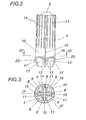
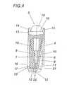
- the propellant cup 4 encloses the projectile 5 positively, the one against the rear end tapered projectile body 6 having a tail unit 7 in the form of radially projecting guide vanes 8, and forms in the gusset region between the guide vanes 8 extending, against the bottom 2 of the cartridge case 1 open pockets 9, on the one hand by a jacket 10 of the propellant bowl 4 and on the other hand by inner walls 11th limited to abut the projectile 5 and separate the projectile from a propellant charge, which is provided in the cartridge case 1 between the bottom 2 and the driving cup 4 and the pockets 9 fills.
- this propellant charge is not shown in the drawing for reasons of clarity. So that the drive cup 4 can penetrate better into the propellant charge when it is pressed into the cartridge case 1, the inner walls 11 bounding the pockets 9 run out in
- the shell 10 of the propellant can 4 has a forwardly tapered lateral surface 13, which is provided with circumferentially distributed longitudinal ribs 14 whose envelope corresponds to an enveloping cylinder of the propellant can 4, so that they run flat against the rear end of the shell 10, such as this particular the Fig. 2 can be removed.
- separation points 15 which may optionally also be designed as predetermined breaking points, must of course not affect the seal between the shell 10 of the propellant bowl 4 and the barrel, because yes, the Austriebskraft depends on this seal. Therefore, the separation points 15 are extended beyond a preferably provided sealing ring 16 also axially to the rear, as shown in the Fig. 2 and 4 is indicated, it is to be ensured by each of the rear end of the separation points 15 enclosing, axial sealing portions 17 for a circumferentially closed seal.
- the projectile 5 forms at its head 18 a re-entrant annular shoulder 19 which is overlapped by the jacket 10 of the propellant can 4.
- the projectile 5 is fixed axially in the propellant cup 4 and can be used together with the propellant cup 4 in the cartridge case 1.
- the holder of the propellant can 4 together with the projectile 5 in the cartridge case 1 is achieved in a conventional manner by a flanged edge 20 of the cartridge case 1, as is the Fig. 1 can be removed.
- the axial support of the shell 10 of the propellant can 4 on the annular shoulder 19 of the projectile head 18 but not only serves for the axial location of the projectile 5 within the propellant can 4, but also causes a relief of the shell 10 of axial compressive forces, the expulsion of the projectile 5 via be acted upon by the propellant gases propellant cup 4 on the jacket 10.
- the jacket 10 is to ensure a minimum deformation in order to improve the sealing effect between the jacket 10 and the barrel by the effective in the pockets 9 propellant gas pressure.
- the projectile 5 can be supported in the axial direction via damping elements 21 at the bottom of the propellant cup 4 in the Fig. 1 and 4
- damping elements 21 are provided in the form of damping ribs 22, which extend transversely to the guide vanes 8 of the projectile 5.
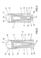
- the embodiment of the Fig. 5 is different from the one after the Fig. 1 to 4 Above all, characterized in that the jacket 10 of the driving cup 4 extends substantially over the entire length of the driving cup 4, which compared to over the shell 10 axially projecting inner walls 11 according to the embodiment of the Fig. 1 to 4 has the disadvantage of a smaller receiving volume for the propellant charge, but has the advantage of obtaining over the axial length of the propellant bowl 4 continuous guidance of the propellant bowl 4 in the barrel, without having to provide additional design measures for this.
- the inner walls 11 in the axial direction The sheath 10 projecting guide ribs 23 in extension of the shell 10. These guide ribs 23 serve in the illustrated design as sealing portions 17.
- the projectile 5 according to the Fig. 5 is also equipped with a guide blade 8 forming tail 7.
- the projectile head 18 has no annular shoulder 19.
- the axial fixing of the projectile 5 in the propellant can 4 is effected by a concave inner wall 24 of the propellant can 10 which projects over the convex head 18.
- the projectile 5 after the Fig. 6 is provided with a luminous tracer unit 25, but otherwise agrees essentially with the after Fig. 1 to 4 match.
- the traction cup 4 forms a closed by a membrane 26 overflow channel 27 for the propellant gases, which break through the membrane 26 upon actuation of the propellant bucket 4 and provide for ignition of the tracer unit 25.
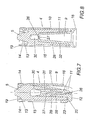
- the projectiles 5 can be adapted to different conditions and varied, as the Fig. 7 to 16 to illustrate some embodiments.
- the propellant cup 4 is to be adapted in each case to the projectile shape. That's how it shows Fig. 7 a projectile 5, which is formed from a hollow body of revolution and its flight guidance obtained by from the bottom-side end face of the projectile shell 28 outgoing mantle recesses 29, through which the pockets 9 of the propellant cup 4 extend.
- an approach 31 of the propellant can 4 with an overflow 27, which opens into the cavity 30 of the projectile 5.
- the diaphragm 26 Since the overflow is closed again with a membrane 26, the diaphragm 26 is broken by a pressurization of the propellant cup 4 by the propellant gases, so that in the cavity 30 during the expulsion of the projectile 5 from a run a corresponding gas pressure can build up after Outlet of the propellant can 4 from the barrel, the detachment of the propellant can 4 from the flying projectile 5 supports.
- Fig. 8 is a cylindrical in its basic form projectile 5 is provided which has a central recess 32 in the projectile base into which a pocket 9 of the propellant cup 4 extends.
- the bottom of the pocket 9 is provided with a closed by a membrane 26 overflow 27, which opens into a recess 32 adjoining the cavity 30 of the projectile 5 to the up in the cavity 30 after breaking through the membrane 26 gas pressure to detach the To use blowing cup 4 from the floor 5, as soon as the driving cup 4 with the projectile 5 exits the barrel.
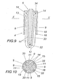
- FIGS. 9 and 10 shows a projectile 5, which has a star-shaped cross-section, which represents a continuous over the floor length tail.
- the pockets 9 of the driving cup 4 thus engage in the gusset area between the star-shaped wings 33 of the projectile 5.
- the bottom of the bag 34 is reinforced, so that the loading pressure can be absorbed by the propellant gases from the propellant cup 4, which can indeed be supported only at the rear end of the star-shaped wings 33 of the projectile 5.
- the projectile after the FIGS. 11 and 12 different from that after the FIGS. 9 and 10 Above all, that it was made of a tubular body, which was folded radially under formation of the axial wings 33, as in particular the Fig. 12 can be removed.
- the outer shape of the projectile 5 thus corresponds to the after FIGS. 9 and 10 , so that there is also a matchingmaschinebecher 4.
- the remaining cavity of the folded-tube body can be filled with a metal 35.
- FIGS. 13 and 14 To produce a projectile shape with a tail 7 from guide vanes 8 can be assumed by an open against the propellant cup 4 hollow body, according to the FIGS. 13 and 14 is folded into guide vanes 8, according to the embodiment of three guide vanes 8.
- these folded guide wings 8 are illustrated, wherein the pockets 9 delimiting inner walls 11 of the driving cup 4 are indicated by dash-dotted lines.
- Particularly simple construction conditions arise when such a projectile 5 is not made in one piece, but consists of a head 18 and an inserted into the hollow head 18 tail 7, the guide wings 8 extend up to the head area, as for example in the 4 to 6 is shown.
- annular chamber Is omitted in the projectile training on a tail and a conically tapering to its bottom 5 according to the FIGS. 15 and 16 used, so that between this projectile 5 and the jacket 10 of the propellant bowl 4 resulting annular chamber can be used as a receiving pocket 9 for receiving a portion of the propellant charge.
- This annular chamber can undergo a division by the axial longitudinal slots of the separation points 15, as the Fig. 16 can be seen.
- the pockets 9 may indeed have no passage points in the region of the jacket 10 to the outside.
- Such a projectile 5, with its central cavity 37, provides a comparative storage volume for firing an agent to the destination.
- the driving cup 4 can be solved easily from the projectile 5, can be dispensed with a continuous surface conditioning of the projectile body on the jacket 10 of the propellant bowl 4 and the driving cup 4 are provided with an axial ribbing 36, as for example in the FIGS. 15 and 16 is shown.
Landscapes
- Engineering & Computer Science (AREA)
- General Engineering & Computer Science (AREA)
- Physics & Mathematics (AREA)
- Fluid Mechanics (AREA)
- Toys (AREA)
- Closures For Containers (AREA)
- Containers And Packaging Bodies Having A Special Means To Remove Contents (AREA)
Abstract
Claims (18)
- Cartouche, avec une douille de cartouche et avec un sabot de propulsion, fabriqué en matière synthétique, recevant, avec une liaison à ajustement de formes, un projectile sous-calibré, inséré dans la douille de cartouche, sabot de propulsion séparant le projectile de la charge propulsive dans la douille de cartouche et présentant, le long de son enveloppe, des points de séparation axiaux, caractérisée en ce que le sabot de propulsion (4) présente au moins une poche (9) ouverte vers le fond (2) de la douille de cartouche (1), s'étendant dans un espace creux entre le projectile (5) et la douille de cartouche (1), sur un tronçon de longueur du projectile (5), pour recevoir une partie de la charge propulsive.
- Cartouche selon la revendication 1, caractérisée en ce que les poches (9) du sabot de propulsion (4) s'étendent entre des ailettes de guidage (8) axiales du projectile (5).
- Cartouche selon la revendication 1 ou 2, caractérisée en ce que le sabot de propulsion (4) forme une poche (9) s'étendant dans un évidement (32) central, dans le fond de projectile.
- Cartouche selon la revendication 1 ou 3, caractérisée en ce que le sabot de propulsion (4) présente une chambre annulaire, entourant le projectile (5) allant en s'effilant de manière conique en évoluant vers son fond, réalisée sous la forme de poche de logement (9) pour une partie de la charge propulsive.
- Cartouche selon l'une des revendications 1 à 4, caractérisée en ce que le sabot de propulsion (4) présente une surface d'enveloppe (13) allant en s'effilant vers l'avant, avec des nervures longitudinales (14) réparties sur la périphérie, dont l'enveloppe correspond à un cylindre d'enveloppe du sabot de propulsion (4).
- Cartouche selon l'une des revendications 1 à 5, caractérisée en ce que le projectile (5) forme, sur sa tête (18), un épaulement annulaire (19) rentrant, serti par le sabot de propulsion (4).
- Cartouche selon l'une des revendications 1 à 6, caractérisée en ce que le sabot de propulsion (4) présente au moins une membrane (26) fermant un canal de transfert (27) par rapport au projectile (5), transpercée par la pression du gaz de propulsion.
- Cartouche selon la revendication 7, caractérisée en ce que le projectile (5) forme un espace creux (30), se raccordant au canal de transfert (27).
- Cartouche selon l'une des revendications 1 à 8, caractérisée en ce que le projectile (5) est composé d'une tête (18) et d'un empennage (7) inséré dans la tête (18) creuse, dont des ailettes de guidage (8) s'étendent jusque dans la zone de tête, et en ce que la tête (18) est repliée, avec effet de serrage, dans la zone de gousset entre les ailettes de guidage (8).
- Cartouche selon l'une des revendications 1 à 8, caractérisée en ce que le projectile (5) forme un corps creux ouvert vers le sabot de propulsion (4), replié en ailettes de guidage (8).
- Cartouche selon l'une des revendications 1 à 8, caractérisée en ce que le projectile (5) présente une section transversale en forme d'étoile.
- Cartouche selon la revendication 11, caractérisée en ce que le projectile (5) est composé d'un corps tubulaire, replié axialement en formant des ailettes axiales (33).
- Cartouche selon l'une des revendications 1 à 12, caractérisée en ce que le sabot de propulsion (4) présente au moins une bague d'étanchéité (16) de pourtour.
- Cartouche selon l'une des revendications 1 à 13, caractérisée en ce que les parois intérieures (11), délimitant les poches (9) du sabot de propulsion (4), évoluent vers la charge propulsive en formant un tranchant (12).
- Cartouche selon l'une des revendications 1 à 14, caractérisée en ce que les parois intérieures (11), délimitant les poches (9) du sabot de propulsion (4), front saillie en direction axiale de l'enveloppe (10) du sabot de propulsion (4), vers le fond (2) de la douille de cartouche (1), et portent des nervures de guidage (23) axiales dans le prolongement de l'enveloppe (10).
- Cartouche selon l'une des revendications 1 à 14, caractérisée en ce que, en direction axiale, le projectile (5) prend appui, par l'intermédiaire d'éléments d'amortissement (21), de préférence au fond du sabot de propulsion (4).
- Cartouche selon la revendication 16, caractérisée en ce que les éléments d'amortissement (21) sont composés de nervures d'amortissement (22), prévues au fond du sabot de propulsion (4), faisant saillie vers le projectile (5).
- Cartouche selon l'une des revendications 1 à 17, caractérisée en ce que les poches (9) du sabot de propulsion (4) sont partiellement remplies d'une masse d'amortissement.
Applications Claiming Priority (2)
| Application Number | Priority Date | Filing Date | Title |
|---|---|---|---|
| AT0167405A AT502547B1 (de) | 2005-10-13 | 2005-10-13 | Patrone |
| PCT/AT2006/000421 WO2007041740A2 (fr) | 2005-10-13 | 2006-10-12 | Cartouche |
Publications (2)
| Publication Number | Publication Date |
|---|---|
| EP1934549A2 EP1934549A2 (fr) | 2008-06-25 |
| EP1934549B1 true EP1934549B1 (fr) | 2011-11-16 |
Family
ID=37685293
Family Applications (1)
| Application Number | Title | Priority Date | Filing Date |
|---|---|---|---|
| EP06804349A Not-in-force EP1934549B1 (fr) | 2005-10-13 | 2006-10-12 | Cartouche |
Country Status (5)
| Country | Link |
|---|---|
| US (1) | US8037830B2 (fr) |
| EP (1) | EP1934549B1 (fr) |
| AT (2) | AT502547B1 (fr) |
| RU (1) | RU2419760C2 (fr) |
| WO (1) | WO2007041740A2 (fr) |
Cited By (1)
| Publication number | Priority date | Publication date | Assignee | Title |
|---|---|---|---|---|
| DE102014019198A1 (de) * | 2014-12-19 | 2016-06-23 | Diehl Bgt Defence Gmbh & Co. Kg | Geschoss |
Families Citing this family (5)
| Publication number | Priority date | Publication date | Assignee | Title |
|---|---|---|---|---|
| KR100843573B1 (ko) * | 2008-03-13 | 2008-07-03 | (주)한국원자력 엔지니어링 | 탄약 |
| RU2631515C1 (ru) * | 2014-08-26 | 2017-09-25 | Ренат Абдульберович Юсупов | Калиберный снаряд с жёстким креплением к корпусу стабилизирующего оперения, пластины которого имеют продолжение на корпус, центрируя снаряд по стволу |
| US10502515B2 (en) * | 2017-01-17 | 2019-12-10 | Raytheon Company | Launch piston brake |
| US10443990B2 (en) * | 2017-06-08 | 2019-10-15 | Connor Yadon | Fragmenting shotgun projectile with radially-disposed segments |
| RU2738519C2 (ru) * | 2019-03-11 | 2020-12-14 | Виталий Анатольевич Денисов | Поддон снаряда съемный |
Family Cites Families (53)
| Publication number | Priority date | Publication date | Assignee | Title |
|---|---|---|---|---|
| US34950A (en) * | 1862-04-15 | Improvement in expanding sabots for hot shot | ||
| US193657A (en) * | 1877-07-31 | Improvement in projectiles | ||
| US178595A (en) * | 1876-06-13 | Improvement in projectiles for ordnance | ||
| US214843A (en) * | 1879-04-29 | Improvement in projectiles for rifled guns | ||
| US1166360A (en) * | 1915-05-22 | 1915-12-28 | Eli E Gregory | Gun cartridge and projectile. |
| US2247563A (en) * | 1939-10-18 | 1941-07-01 | Robert S Spalding | Projectile |
| US2991719A (en) * | 1944-06-24 | 1961-07-11 | Millar John Mcg | Projectile |
| US2993444A (en) * | 1945-08-02 | 1961-07-25 | Charles E Hablutzel | Sabot retainer |
| US2669930A (en) * | 1946-01-05 | 1954-02-23 | Remington Arms Co Inc | Sabot projectile |
| US2982212A (en) * | 1955-12-29 | 1961-05-02 | Jr Ralph O Robinson | Base fuze protector |
| US3055268A (en) * | 1960-12-08 | 1962-09-25 | Rosenthal Henry | Discarding obturator and rotator for projectiles |
| US3164092A (en) * | 1962-11-13 | 1965-01-05 | Remington Arms Co Inc | Ammunition sabot |
| US3242866A (en) * | 1964-09-25 | 1966-03-29 | Richard L Malter | Primary and secondary projectile |
| NL6514247A (fr) * | 1964-12-22 | 1966-06-23 | ||
| US3318244A (en) | 1965-07-01 | 1967-05-09 | Charles E Rostocil | Cartridge |
| NL137889C (fr) * | 1967-07-28 | |||
| US3431815A (en) * | 1968-01-24 | 1969-03-11 | Us Army | Discardable rotating band |
| DE2630830A1 (de) | 1976-07-09 | 1978-01-19 | Dynamit Nobel Ag | Treibspiegelgeschoss |
| DE2642222C2 (de) * | 1976-09-20 | 1983-11-10 | Rheinmetall GmbH, 4000 Düsseldorf | Drallstabilisiertes Ringgeschoß |
| CH622883A5 (fr) * | 1977-07-21 | 1981-04-30 | Oerlikon Buehrle Ag | |
| US4175493A (en) * | 1977-11-07 | 1979-11-27 | John Daily | Patch for muzzle loading firearms |
| DE2836963A1 (de) | 1978-08-24 | 1984-03-08 | Rheinmetall GmbH, 4000 Düsseldorf | Munition-einheit fuer rohrwaffen |
| DE3037560A1 (de) * | 1980-10-04 | 1984-11-29 | Rheinmetall GmbH, 4000 Düsseldorf | Panzerbrechendes geschoss |
| US4434718A (en) | 1981-09-11 | 1984-03-06 | Kopsch Paul J | Sabot and projectile |
| US4709638A (en) * | 1981-09-24 | 1987-12-01 | Honeywell Inc. | Discarding sabot projectile |
| FR2555728B1 (fr) * | 1983-11-29 | 1987-03-20 | Sauvestre Jean Claude | Munition pour arme de chasse |
| AT386896B (de) * | 1986-07-08 | 1988-10-25 | Steyr Daimler Puch Ag | Patrone fuer schusswaffen |
| DE3811597A1 (de) | 1988-04-07 | 1989-10-19 | Dynamit Nobel Ag | Treibkaefig fuer ein unterkalibergeschoss |
| DE3824524A1 (de) | 1988-07-20 | 1990-02-08 | Wegmann & Co | Panzerbrechendes geschoss |
| DE3843289A1 (de) * | 1988-12-22 | 1990-06-28 | Diehl Gmbh & Co | Treibspiegelmunition |
| FR2647891B1 (fr) * | 1989-06-01 | 1994-05-20 | Etat Francais Delegue Armement | Dispositif de maintien d'un projectile sous-calibre relativement a l'enveloppe d'une munition telescopee |
| US4936220A (en) * | 1989-07-03 | 1990-06-26 | The United States Of America As Represented By The Secretary Of The Army | Solid propellant-carrying caboted projectile |
| DE4026902C2 (de) * | 1990-08-25 | 1995-01-05 | Rheinmetall Gmbh | Geschoß |
| US5359938A (en) * | 1990-10-24 | 1994-11-01 | Olin Corporation | Ultra light weight sabot |
| US5192830A (en) * | 1992-01-29 | 1993-03-09 | The United States Of America As Represented By The Secretary Of The Army | Sabot for high dispersion shot shell |
| US5189251A (en) * | 1992-01-29 | 1993-02-23 | The United States Of America As Represented By The Secretary Of The Army | Sabot for high dispersion shot shell |
| US5214238A (en) * | 1992-03-23 | 1993-05-25 | Christopher Young | Sabot for chambering conventional bullets in a shotgun |
| US5339743A (en) | 1993-07-12 | 1994-08-23 | Remington Arms Company, Inc. | Ammunition system comprising slug holding sabot and slug type shot shell |
| EG21731A (en) * | 1993-09-24 | 2002-02-27 | Contraves Pyrotec Ag | Releasable sabot for a subcaliber projectile |
| US5710391A (en) * | 1993-10-12 | 1998-01-20 | Chetcuti; Francis | Recoil reducer wad for ammunition |
| US5415102A (en) * | 1994-05-13 | 1995-05-16 | White; Gary B. | Muzzle loading sabot |
| FR2726357B1 (fr) * | 1994-10-26 | 1997-01-17 | Sauvestre Jean Claude | Balle de chasse a fleche telescopee, comportant un sous-projectile associe a un lanceur |
| DE19741841C2 (de) | 1997-09-23 | 2000-07-06 | Rheinmetall W & M Gmbh | Verfahren zur Herstellung einer Patrone |
| US6073560A (en) | 1998-03-09 | 2000-06-13 | Remington Arms Company, Inc. | Sabot |
| DE10157668B4 (de) * | 2001-11-24 | 2014-05-22 | Rheinmetall Waffe Munition Gmbh | Geschoss |
| DE10244571C1 (de) * | 2002-09-25 | 2003-12-04 | Wilhelm Brenneke Gmbh & Co Kg | Flintenlaufgeschoss |
| US6895865B2 (en) * | 2003-03-20 | 2005-05-24 | Hornady Manufacturing Company | Sabot for muzzleloading firearm |
| US7451705B2 (en) * | 2004-03-17 | 2008-11-18 | Fry Grant R | Non-discarding sabot projectile system |
| US7451706B2 (en) * | 2005-01-25 | 2008-11-18 | Olin Corporation | Short magnum shotshell cartridge and firing assembly |
| US20060278114A1 (en) * | 2005-05-16 | 2006-12-14 | Hornady Manufacturing Company | Shotgun shell with slug |
| US7243603B2 (en) * | 2005-07-12 | 2007-07-17 | Sheaffer Clifford G | Shot pattern control wad structure for shotshell |
| AT502514B1 (de) * | 2005-10-13 | 2007-04-15 | Winter Udo Mag | Unterkalibriges geschoss |
| RU2349869C1 (ru) * | 2007-12-13 | 2009-03-20 | Михаил Юрьевич Иванов | Пулевой снаряд для охотничьих ружей с гладкими стволами и "парадоксами" |
-
2005
- 2005-10-13 AT AT0167405A patent/AT502547B1/de not_active IP Right Cessation
-
2006
- 2006-10-12 WO PCT/AT2006/000421 patent/WO2007041740A2/fr not_active Ceased
- 2006-10-12 US US12/083,319 patent/US8037830B2/en not_active Expired - Fee Related
- 2006-10-12 AT AT06804349T patent/ATE534013T1/de active
- 2006-10-12 RU RU2008118477/11A patent/RU2419760C2/ru not_active IP Right Cessation
- 2006-10-12 EP EP06804349A patent/EP1934549B1/fr not_active Not-in-force
Cited By (1)
| Publication number | Priority date | Publication date | Assignee | Title |
|---|---|---|---|---|
| DE102014019198A1 (de) * | 2014-12-19 | 2016-06-23 | Diehl Bgt Defence Gmbh & Co. Kg | Geschoss |
Also Published As
| Publication number | Publication date |
|---|---|
| WO2007041740A2 (fr) | 2007-04-19 |
| WO2007041740A3 (fr) | 2007-07-12 |
| AT502547A1 (de) | 2007-04-15 |
| RU2008118477A (ru) | 2009-11-20 |
| AT502547B1 (de) | 2009-10-15 |
| EP1934549A2 (fr) | 2008-06-25 |
| RU2419760C2 (ru) | 2011-05-27 |
| ATE534013T1 (de) | 2011-12-15 |
| US8037830B2 (en) | 2011-10-18 |
| US20090064887A1 (en) | 2009-03-12 |
Similar Documents
| Publication | Publication Date | Title |
|---|---|---|
| DE69225232T2 (de) | Jagdkugel mit reduzierter absetzung von blei in die umwelt | |
| DE1958925A1 (de) | Patrone | |
| DE2914049C2 (de) | Patrone | |
| DE69915427T2 (de) | Munitionskartusche mit ihrer Treibladungskonfiguration | |
| DE2242719A1 (de) | Patronen- und geschoss-anordnung | |
| DE4123649C2 (de) | Ausstoßvorrichtung | |
| CH625613A5 (fr) | ||
| DE3238269A1 (de) | Uebungspatrone mit plastik-geschoss oder -geschossnachbildung | |
| DE7818115U1 (de) | Treibspiegelgeschoss mit pyrotechnischem satz | |
| DE60104950T2 (de) | Anzündrohr für artilleriemunition | |
| DE3617415C2 (de) | Unterkalibriges Treibspiegelgeschoß | |
| DE1003516B (de) | Antrieb fuer pulvergetriebene Raketen oder Geschosse mit Eigenantrieb | |
| AT502547B1 (de) | Patrone | |
| DE2458696A1 (de) | Sicherheitszuendkoerper fuer eine knallzuendschnur | |
| EP0303198B1 (fr) | Cartouche pour expulser des liquides par pression | |
| CH662646A5 (de) | Geschoss mit einem rohrfoermigen koerper. | |
| AT502514B1 (de) | Unterkalibriges geschoss | |
| EP3312546A1 (fr) | Projectile à usage multiple | |
| DE949726C (de) | Kraftgas erzeugende Ladung | |
| DE611842C (de) | Brandgeschoss | |
| DE2324482B2 (de) | Patronenhülse für Schlagzundung | |
| DE1428678B2 (de) | Ubungsgranate | |
| DE202014103662U1 (de) | Bleifreies Teilzerlegungsgeschoss für Jagdzwecke | |
| DE1138341B (de) | Platzpatrone ohne Splitterentwicklung | |
| DE102004062931A1 (de) | Patrone |
Legal Events
| Date | Code | Title | Description |
|---|---|---|---|
| PUAI | Public reference made under article 153(3) epc to a published international application that has entered the european phase |
Free format text: ORIGINAL CODE: 0009012 |
|
| 17P | Request for examination filed |
Effective date: 20080328 |
|
| AK | Designated contracting states |
Kind code of ref document: A2 Designated state(s): AT BE BG CH CY CZ DE DK EE ES FI FR GB GR HU IE IS IT LI LT LU LV MC NL PL PT RO SE SI SK TR |
|
| 17Q | First examination report despatched |
Effective date: 20090806 |
|
| GRAP | Despatch of communication of intention to grant a patent |
Free format text: ORIGINAL CODE: EPIDOSNIGR1 |
|
| DAX | Request for extension of the european patent (deleted) | ||
| GRAS | Grant fee paid |
Free format text: ORIGINAL CODE: EPIDOSNIGR3 |
|
| GRAA | (expected) grant |
Free format text: ORIGINAL CODE: 0009210 |
|
| RIN1 | Information on inventor provided before grant (corrected) |
Inventor name: WINTER, UDO |
|
| AK | Designated contracting states |
Kind code of ref document: B1 Designated state(s): AT BE BG CH CY CZ DE DK EE ES FI FR GB GR HU IE IS IT LI LT LU LV MC NL PL PT RO SE SI SK TR |
|
| REG | Reference to a national code |
Ref country code: GB Ref legal event code: FG4D Free format text: NOT ENGLISH |
|
| REG | Reference to a national code |
Ref country code: CH Ref legal event code: EP |
|
| REG | Reference to a national code |
Ref country code: IE Ref legal event code: FG4D Free format text: LANGUAGE OF EP DOCUMENT: GERMAN |
|
| REG | Reference to a national code |
Ref country code: DE Ref legal event code: R096 Ref document number: 502006010609 Country of ref document: DE Effective date: 20120112 |
|
| REG | Reference to a national code |
Ref country code: NL Ref legal event code: VDEP Effective date: 20111116 |
|
| LTIE | Lt: invalidation of european patent or patent extension |
Effective date: 20111116 |
|
| PG25 | Lapsed in a contracting state [announced via postgrant information from national office to epo] |
Ref country code: LT Free format text: LAPSE BECAUSE OF FAILURE TO SUBMIT A TRANSLATION OF THE DESCRIPTION OR TO PAY THE FEE WITHIN THE PRESCRIBED TIME-LIMIT Effective date: 20111116 Ref country code: IS Free format text: LAPSE BECAUSE OF FAILURE TO SUBMIT A TRANSLATION OF THE DESCRIPTION OR TO PAY THE FEE WITHIN THE PRESCRIBED TIME-LIMIT Effective date: 20120316 |
|
| PG25 | Lapsed in a contracting state [announced via postgrant information from national office to epo] |
Ref country code: PL Free format text: LAPSE BECAUSE OF FAILURE TO SUBMIT A TRANSLATION OF THE DESCRIPTION OR TO PAY THE FEE WITHIN THE PRESCRIBED TIME-LIMIT Effective date: 20111116 Ref country code: NL Free format text: LAPSE BECAUSE OF FAILURE TO SUBMIT A TRANSLATION OF THE DESCRIPTION OR TO PAY THE FEE WITHIN THE PRESCRIBED TIME-LIMIT Effective date: 20111116 Ref country code: SE Free format text: LAPSE BECAUSE OF FAILURE TO SUBMIT A TRANSLATION OF THE DESCRIPTION OR TO PAY THE FEE WITHIN THE PRESCRIBED TIME-LIMIT Effective date: 20111116 Ref country code: GR Free format text: LAPSE BECAUSE OF FAILURE TO SUBMIT A TRANSLATION OF THE DESCRIPTION OR TO PAY THE FEE WITHIN THE PRESCRIBED TIME-LIMIT Effective date: 20120217 Ref country code: SI Free format text: LAPSE BECAUSE OF FAILURE TO SUBMIT A TRANSLATION OF THE DESCRIPTION OR TO PAY THE FEE WITHIN THE PRESCRIBED TIME-LIMIT Effective date: 20111116 Ref country code: LV Free format text: LAPSE BECAUSE OF FAILURE TO SUBMIT A TRANSLATION OF THE DESCRIPTION OR TO PAY THE FEE WITHIN THE PRESCRIBED TIME-LIMIT Effective date: 20111116 Ref country code: PT Free format text: LAPSE BECAUSE OF FAILURE TO SUBMIT A TRANSLATION OF THE DESCRIPTION OR TO PAY THE FEE WITHIN THE PRESCRIBED TIME-LIMIT Effective date: 20120316 |
|
| REG | Reference to a national code |
Ref country code: IE Ref legal event code: FD4D |
|
| PG25 | Lapsed in a contracting state [announced via postgrant information from national office to epo] |
Ref country code: CY Free format text: LAPSE BECAUSE OF FAILURE TO SUBMIT A TRANSLATION OF THE DESCRIPTION OR TO PAY THE FEE WITHIN THE PRESCRIBED TIME-LIMIT Effective date: 20111116 |
|
| PG25 | Lapsed in a contracting state [announced via postgrant information from national office to epo] |
Ref country code: DK Free format text: LAPSE BECAUSE OF FAILURE TO SUBMIT A TRANSLATION OF THE DESCRIPTION OR TO PAY THE FEE WITHIN THE PRESCRIBED TIME-LIMIT Effective date: 20111116 Ref country code: IE Free format text: LAPSE BECAUSE OF FAILURE TO SUBMIT A TRANSLATION OF THE DESCRIPTION OR TO PAY THE FEE WITHIN THE PRESCRIBED TIME-LIMIT Effective date: 20111116 Ref country code: CZ Free format text: LAPSE BECAUSE OF FAILURE TO SUBMIT A TRANSLATION OF THE DESCRIPTION OR TO PAY THE FEE WITHIN THE PRESCRIBED TIME-LIMIT Effective date: 20111116 Ref country code: EE Free format text: LAPSE BECAUSE OF FAILURE TO SUBMIT A TRANSLATION OF THE DESCRIPTION OR TO PAY THE FEE WITHIN THE PRESCRIBED TIME-LIMIT Effective date: 20111116 Ref country code: SK Free format text: LAPSE BECAUSE OF FAILURE TO SUBMIT A TRANSLATION OF THE DESCRIPTION OR TO PAY THE FEE WITHIN THE PRESCRIBED TIME-LIMIT Effective date: 20111116 Ref country code: BG Free format text: LAPSE BECAUSE OF FAILURE TO SUBMIT A TRANSLATION OF THE DESCRIPTION OR TO PAY THE FEE WITHIN THE PRESCRIBED TIME-LIMIT Effective date: 20120216 |
|
| PG25 | Lapsed in a contracting state [announced via postgrant information from national office to epo] |
Ref country code: RO Free format text: LAPSE BECAUSE OF FAILURE TO SUBMIT A TRANSLATION OF THE DESCRIPTION OR TO PAY THE FEE WITHIN THE PRESCRIBED TIME-LIMIT Effective date: 20111116 Ref country code: IT Free format text: LAPSE BECAUSE OF FAILURE TO SUBMIT A TRANSLATION OF THE DESCRIPTION OR TO PAY THE FEE WITHIN THE PRESCRIBED TIME-LIMIT Effective date: 20111116 |
|
| PLBE | No opposition filed within time limit |
Free format text: ORIGINAL CODE: 0009261 |
|
| STAA | Information on the status of an ep patent application or granted ep patent |
Free format text: STATUS: NO OPPOSITION FILED WITHIN TIME LIMIT |
|
| 26N | No opposition filed |
Effective date: 20120817 |
|
| REG | Reference to a national code |
Ref country code: DE Ref legal event code: R097 Ref document number: 502006010609 Country of ref document: DE Effective date: 20120817 |
|
| BERE | Be: lapsed |
Owner name: WINTER, UDO Effective date: 20121031 |
|
| PG25 | Lapsed in a contracting state [announced via postgrant information from national office to epo] |
Ref country code: ES Free format text: LAPSE BECAUSE OF FAILURE TO SUBMIT A TRANSLATION OF THE DESCRIPTION OR TO PAY THE FEE WITHIN THE PRESCRIBED TIME-LIMIT Effective date: 20120227 |
|
| PG25 | Lapsed in a contracting state [announced via postgrant information from national office to epo] |
Ref country code: MC Free format text: LAPSE BECAUSE OF NON-PAYMENT OF DUE FEES Effective date: 20121031 |
|
| REG | Reference to a national code |
Ref country code: CH Ref legal event code: PL |
|
| GBPC | Gb: european patent ceased through non-payment of renewal fee |
Effective date: 20121012 |
|
| PG25 | Lapsed in a contracting state [announced via postgrant information from national office to epo] |
Ref country code: FI Free format text: LAPSE BECAUSE OF FAILURE TO SUBMIT A TRANSLATION OF THE DESCRIPTION OR TO PAY THE FEE WITHIN THE PRESCRIBED TIME-LIMIT Effective date: 20111116 |
|
| REG | Reference to a national code |
Ref country code: FR Ref legal event code: ST Effective date: 20130628 |
|
| PG25 | Lapsed in a contracting state [announced via postgrant information from national office to epo] |
Ref country code: LI Free format text: LAPSE BECAUSE OF NON-PAYMENT OF DUE FEES Effective date: 20121031 Ref country code: BE Free format text: LAPSE BECAUSE OF NON-PAYMENT OF DUE FEES Effective date: 20121031 Ref country code: DE Free format text: LAPSE BECAUSE OF NON-PAYMENT OF DUE FEES Effective date: 20130501 Ref country code: CH Free format text: LAPSE BECAUSE OF NON-PAYMENT OF DUE FEES Effective date: 20121031 Ref country code: GB Free format text: LAPSE BECAUSE OF NON-PAYMENT OF DUE FEES Effective date: 20121012 |
|
| REG | Reference to a national code |
Ref country code: DE Ref legal event code: R119 Ref document number: 502006010609 Country of ref document: DE Effective date: 20130501 |
|
| PG25 | Lapsed in a contracting state [announced via postgrant information from national office to epo] |
Ref country code: FR Free format text: LAPSE BECAUSE OF NON-PAYMENT OF DUE FEES Effective date: 20121031 |
|
| REG | Reference to a national code |
Ref country code: AT Ref legal event code: MM01 Ref document number: 534013 Country of ref document: AT Kind code of ref document: T Effective date: 20121031 |
|
| PG25 | Lapsed in a contracting state [announced via postgrant information from national office to epo] |
Ref country code: AT Free format text: LAPSE BECAUSE OF NON-PAYMENT OF DUE FEES Effective date: 20121031 |
|
| PG25 | Lapsed in a contracting state [announced via postgrant information from national office to epo] |
Ref country code: TR Free format text: LAPSE BECAUSE OF FAILURE TO SUBMIT A TRANSLATION OF THE DESCRIPTION OR TO PAY THE FEE WITHIN THE PRESCRIBED TIME-LIMIT Effective date: 20111116 |
|
| PG25 | Lapsed in a contracting state [announced via postgrant information from national office to epo] |
Ref country code: LU Free format text: LAPSE BECAUSE OF NON-PAYMENT OF DUE FEES Effective date: 20121012 |
|
| PG25 | Lapsed in a contracting state [announced via postgrant information from national office to epo] |
Ref country code: HU Free format text: LAPSE BECAUSE OF FAILURE TO SUBMIT A TRANSLATION OF THE DESCRIPTION OR TO PAY THE FEE WITHIN THE PRESCRIBED TIME-LIMIT Effective date: 20061012 |