EP1934576B1 - Procede et dispositif de test d'une eprouvette soumise un essai de flexion rotative et de torsion combine - Google Patents
Procede et dispositif de test d'une eprouvette soumise un essai de flexion rotative et de torsion combine Download PDFInfo
- Publication number
- EP1934576B1 EP1934576B1 EP06792417A EP06792417A EP1934576B1 EP 1934576 B1 EP1934576 B1 EP 1934576B1 EP 06792417 A EP06792417 A EP 06792417A EP 06792417 A EP06792417 A EP 06792417A EP 1934576 B1 EP1934576 B1 EP 1934576B1
- Authority
- EP
- European Patent Office
- Prior art keywords
- sample
- electric motor
- torsional
- stress
- bending
- Prior art date
- Legal status (The legal status is an assumption and is not a legal conclusion. Google has not performed a legal analysis and makes no representation as to the accuracy of the status listed.)
- Not-in-force
Links
- 238000005452 bending Methods 0.000 title claims abstract description 32
- 238000000034 method Methods 0.000 title claims abstract description 24
- 230000008878 coupling Effects 0.000 claims description 7
- 238000010168 coupling process Methods 0.000 claims description 7
- 238000005859 coupling reaction Methods 0.000 claims description 7
- 238000010998 test method Methods 0.000 claims description 2
- 230000005540 biological transmission Effects 0.000 claims 2
- 239000012530 fluid Substances 0.000 claims 1
- 238000012360 testing method Methods 0.000 abstract description 42
- 239000000523 sample Substances 0.000 description 48
- 239000000463 material Substances 0.000 description 11
- 125000004122 cyclic group Chemical group 0.000 description 4
- 238000002485 combustion reaction Methods 0.000 description 2
- 238000002474 experimental method Methods 0.000 description 2
- 238000011160 research Methods 0.000 description 2
- 230000003068 static effect Effects 0.000 description 2
- 230000000903 blocking effect Effects 0.000 description 1
- 238000013461 design Methods 0.000 description 1
- 238000001514 detection method Methods 0.000 description 1
- 238000011161 development Methods 0.000 description 1
- 238000010586 diagram Methods 0.000 description 1
- 238000005265 energy consumption Methods 0.000 description 1
- 238000004880 explosion Methods 0.000 description 1
- 238000011835 investigation Methods 0.000 description 1
- 239000000725 suspension Substances 0.000 description 1
Images

Classifications
-
- G—PHYSICS
- G01—MEASURING; TESTING
- G01N—INVESTIGATING OR ANALYSING MATERIALS BY DETERMINING THEIR CHEMICAL OR PHYSICAL PROPERTIES
- G01N3/00—Investigating strength properties of solid materials by application of mechanical stress
- G01N3/32—Investigating strength properties of solid materials by application of mechanical stress by applying repeated or pulsating forces
-
- G—PHYSICS
- G01—MEASURING; TESTING
- G01N—INVESTIGATING OR ANALYSING MATERIALS BY DETERMINING THEIR CHEMICAL OR PHYSICAL PROPERTIES
- G01N2203/00—Investigating strength properties of solid materials by application of mechanical stress
- G01N2203/0014—Type of force applied
- G01N2203/0021—Torsional
-
- G—PHYSICS
- G01—MEASURING; TESTING
- G01N—INVESTIGATING OR ANALYSING MATERIALS BY DETERMINING THEIR CHEMICAL OR PHYSICAL PROPERTIES
- G01N2203/00—Investigating strength properties of solid materials by application of mechanical stress
- G01N2203/0014—Type of force applied
- G01N2203/0023—Bending
-
- G—PHYSICS
- G01—MEASURING; TESTING
- G01N—INVESTIGATING OR ANALYSING MATERIALS BY DETERMINING THEIR CHEMICAL OR PHYSICAL PROPERTIES
- G01N2203/00—Investigating strength properties of solid materials by application of mechanical stress
- G01N2203/0014—Type of force applied
- G01N2203/0026—Combination of several types of applied forces
- G01N2203/0028—Rotation and bending
-
- G—PHYSICS
- G01—MEASURING; TESTING
- G01N—INVESTIGATING OR ANALYSING MATERIALS BY DETERMINING THEIR CHEMICAL OR PHYSICAL PROPERTIES
- G01N2203/00—Investigating strength properties of solid materials by application of mechanical stress
- G01N2203/02—Details not specific for a particular testing method
- G01N2203/025—Geometry of the test
- G01N2203/0258—Non axial, i.e. the forces not being applied along an axis of symmetry of the specimen
Definitions
- the invention relates to a method and a device for testing a specimen under combined Umlaufbiege- and torsional stress, preferably at high frequency of one or both stresses.
- DE 37 16 215 A1 discloses a rotary bending testing machine with torsion loading means for introducing a circumferential bending moment and a torsional load into a test piece.
- FR-A-2411403 discloses an apparatus for testing a sample by subjecting it to torsional stress by torsional stresses applied to two opposite end portions of the sample and applying a bending stress at a location between the end portions.
- JP 2004150976 A discloses a load tester for torsional bending and axle load.
- JP 200227392 A discloses a combined torsional bending load testing machine.
- JP 7260652 A discloses a static load tester.
- JP 61014541 A discloses a torsion and bending test machine.
- the invention has for its object to provide a method and an apparatus which allow a test of a specimen under combined Umlaufbiegeund Torsionsbe screwung, with a test result can be obtained in a short time, with the lowest possible energy consumption.
- a very efficient energy saving is inventively achieved in that the electrical circuits of the two electric motors are coupled, with energy for the driving electric motor can be supplied by the engine currently in braking operation.
- the bending stress of the sample according to an exemplary embodiment of the invention can be realized by the force is applied via the stator of each electric motor, wherein the bending stress over the test length is constant in size.
- test device allows a vibration test under pure torsional vibration and pure Umlaufbiege LCDbe.
- the sample can be tested under combined Umlaufbiege- and torsional stress at high frequency.
- a "high frequency” can be understood as a frequency above 15 Hz, in particular a frequency of at least 30 Hz.
- the frequency can be up to 60 Hz and more, whereas in conventional, servohydraulic systems is an upper limit at 15 Hz.
- the in-rotation of the sample may comprise relatively in-rotation of the sample with respect to an electric motor.
- an electric motor may (at least partially) rest in a laboratory system and the sample may be rotated relative to the electric motor and to the laboratory system. But it can also rotate an electric motor (for example, a servo motor) with respect to the laboratory system and rest the sample in the laboratory system.
- the exposure of the sample to torsional stress may be effected by torsional moments applied to two opposite end portions of the sample.
- Alternative suspensions are possible, but it is advantageous that the power flow is substantially in the middle of the sample.
- the torsional moments can be generated by an electric motor (for example by means of servomotors).
- an electric motor for example by means of servomotors.
- an internal combustion engine or another sufficiently strong drive mechanism can be used.
- the bending stress may be applied over two opposite end portions of the sample, at a location between their end portions, or at one or more other locations.
- a change-over behavior of the sample can be detected.
- two rotary angle sensors of the electric motors can be used to determine the shear distortions in the Test cross section and a measuring device for detecting the local normal stresses in the material sample can be used. This can be done for example via a linear measuring device. This may allow to obtain additional information that may be used, for example, in material modeling.
- Servo motors are preferably used as electric motors.
- each electric motor is equipped with a rotary encoder according to an exemplary embodiment of the invention and a torque measuring device is provided between the electric motors, the measured data can be fed to a torque controller.
- the application of force for the bending stress of the specimen is carried out according to an exemplary embodiment of the invention by means of a power device, such as a lifting spindle or a pressure cylinder, which power device is coupled to a carrier on both sides of the coupling with the power device via lever a lever system is coupled to one stator of the electric motors.
- a power device such as a lifting spindle or a pressure cylinder
- the distance of the linkages of the levers of the lever system on the carrier and / or on the stator is variable to set different bending stresses.
- a preferred embodiment is characterized in that the coupling of the power device with the carrier via an elastically resilient element, preferably designed as a helical spring, is realized.
- Embodiments of the device (s) disclosed in this patent application also apply to the method, and vice versa
- FIG. 1 an overall view of an apparatus for testing a specimen under combined Umlaufbiege- and torsional stress illustrated in accordance with an exemplary embodiment of the invention.
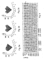
- the Fig. 2a to. 2c show different fracture surfaces of the specimen for different set frequency ratios.
- the Fig. 3a and Fig. 3b each show photographs of the fracture surface of a sample in front view and in side view.
- Fig. 4 represents a torsional moment-time curve in diagram form.
- a sample which is formed by a cylindrical rod, for example having a diameter in the range between 5 and 10 mm, preferably 6 to 7.5 mm. Other test diameters are possible.
- a clamping device 2 is provided, with which the sample 1 is connected to a respective drive shaft 3 of an electric drive motor 4.
- One of the electric motors 4 is equipped with a torque load cell 5.
- the electric motors 4, which are designed as servomotors are with their stators to a pivot axis 6 pivotally mounted relative to a foundation 7, which pivot axes 6 extend transversely to the drive shafts 3 of the electric motors 4 and parallel to each other.
- Each electric motor 4 has a rotary encoder 8 and is equipped with a servo converter 9, via which a torsional torque can be cyclically applied to each of the two electric motors 4.
- the sample 1 thus experiences a cyclic torsional moment load with possible Torsionsstoffmomentüberlagerung.
- the two electric motors 4 are electrically coupled, which means that the currently braking electric motor 4 supplies a large part of the energy for the driving electric motor.
- a force device 10 such as a lifting spindle, is provided, with which a carrier 11 can be loaded approximately in the middle of its longitudinal extent.
- a force device 10 such as a lifting spindle
- levers 13 of a lever system are articulated, via which the force transmitted by the lifting spindle 10 to the carrier 11 can be transmitted to the stators of the two electric motors 4.
- the articulation points of the lever 13 of the lever system on the carrier 11 and / or on the respective stator are variable for the precise adjustment of certain bending stresses of the sample 1, so that their distance from the coupling of the carrier 11 with the power device 10 is adjustable.
- the force device 10 is coupled to the carrier 11 via an elastic intermediate member 14, such as a coil spring.
- both the force transmitted from the force device 10 to the carrier 11 and the torque amplitude and the torque mean value for the two electric motors 4 can be varied.
- a computer unit 16 Connected to the control unit 15 is a computer unit 16 with a screen for displaying the results.
- the combined orbital torsion twisting apparatus of the present invention allows trial trials which are not possible with conventional tensile torsion testing machines.
- One reason for this is that in the case of rotational bending torsion, several highly stressed points occur in the test cross section depending on the selected frequency ratio f ⁇ / ⁇ .
- the frequency ratio is 1, according to Fig. 2b 2nd and according to Fig. 2c 3 .
- Combined circumferential bending / torsion therefore provides additional information which is very important for describing the fatigue behavior of materials.
- Fig. 3a and 3b show fracture surfaces of a sample 1 tested according to the invention. At the fracture surface, a primary tear 18 and a secondary tear 19 can be seen,
- the device can be operated with different test loads. In the design, attention should be paid to a precise tuning of the vibration conditions.
- the device can also be operated in the range of the natural torsional frequency of the test device, whereby higher torsional moments can be realized.
- the Torsionseigenfrequenz can be influenced by changing the inertia, for example, by arranging different masses of inertia.
Landscapes
- Physics & Mathematics (AREA)
- Health & Medical Sciences (AREA)
- Life Sciences & Earth Sciences (AREA)
- Chemical & Material Sciences (AREA)
- Analytical Chemistry (AREA)
- Biochemistry (AREA)
- General Health & Medical Sciences (AREA)
- General Physics & Mathematics (AREA)
- Immunology (AREA)
- Pathology (AREA)
- Investigating Strength Of Materials By Application Of Mechanical Stress (AREA)
Claims (15)
- Procédé de contrôle d'échantillon (1) sous l'effet d'un effort combiné de flexion rotative et de torsion, ledit procédé comprenant les étapes consistant à :- mettre l'échantillon en rotation (1) ;- soumettre l'échantillon (1) à un effort de torsion par des moments de torsion exercés au niveau de deux zones de l'échantillon (1), ainsi que- soumettre l'échantillon (1) à un effort de flexion ;dans lequel un moment de torsion généré par un moteur électrique est exercé sur l'échantillon (1) en ce que l'échantillon (1) est mis en rotation au niveau d'une zone d'extrémité au moyen d'un premier moteur électrique (4) à un régime prédéterminé et est couplé au niveau d'une autre zone d'extrémité avec un deuxième moteur électrique (4), et les deux moteurs électriques (4) génèrent un moment de torsion sur l'échantillon (1) par une torsion mutuelle; et
dans lequel des circuits électriques des deux moteurs électriques (4) sont couplés, dans lequel de l'énergie pour le moteur électrique (4) d'entraînement est fournie par le moteur se trouvant actuellement en mode de freinage. - Procédé selon la revendication 1, dans lequel l'effort de flexion de l'échantillon (1) est provoqué par un transfert de charge effectué par l'intermédiaire d'un stator de chaque moteur électrique (4).
- Procédé selon les revendications 1 ou 2, dans lequel l'échantillon (1) est contrôlé sous l'effet d'un effort combiné de flexion rotative et de torsion à une fréquence au-dessus de 15 Hz d'un ou des deux efforts.
- Procédé selon l'une quelconque des revendications 1 à 3, dans lequel la mise en rotation de l'échantillon (1) présente une mise en rotation relative de l'échantillon (1) par rapport à un moteur électrique (4) de telle sorte
que le premier ou le deuxième moteur électrique (4) est immobilisé dans un système expérimental et l'échantillon (1) est amené à tourner par rapport au premier ou deuxième moteur électrique (4) et par rapport au système expérimental, ou
que le premier ou deuxième moteur électrique (4) est amené à tourner par rapport au système expérimental et l'échantillon (1) est immobilisé dans le système expérimental. - Procédé selon l'une quelconque des revendications 1 à 4, dans lequel le fait de soumettre l'échantillon (1) à un effort de torsion s'effectue par des moments de torsion exercés au niveau de deux zones d'extrémité mutuellement opposées de l'échantillon (1).
- Procédé selon l'une quelconque des revendications 1 à 5, dans lequel les moments de torsion exercés sont générés de façon électromotrice.
- Procédé selon l'une quelconque des revendications 1 à 6, dans lequel l'effort de flexion est exercé soit par l'intermédiaire de deux zones d'extrémité mutuellement opposées de l'échantillon (1), soit à un endroit entre les zones d'extrémité de celui-ci.
- Procédé selon l'une quelconque des revendications 1 à 7, dans lequel un comportement de déformation réciproque de l'échantillon (1) est détecté.
- Dispositif pour mettre en oeuvre le procédé selon l'une quelconque des revendications 1 à 8, dans lequel ledit dispositif présente :- deux dispositifs de serrage (2), pouvant respectivement être mis en rotation par un moteur électrique (4), pour serrer un échantillon (1) respectivement par une extrémité dans l'un des dispositifs de serrage (2), lesdits moteurs électriques pouvant être entraînés avec des moments de torsion mutuellement opposés, et- un dispositif mécanique chassant les dispositifs de serrage (2) d'une position alignée afin de soumettre l'échantillon (1) à un effort de flexion,où des circuits électriques des deux moteurs électriques (4) sont couplés de telle manière que de l'énergie pour le moteur électrique (4) d'entraînement soit fournie par le moteur se trouvant actuellement en mode de freinage.
- Dispositif selon la revendication 9, dans lequel des servomoteurs sont utilisés en tant que moteurs électriques (4).
- Dispositif selon les revendications 9 ou 10, dans lequel chaque moteur électrique (4) est équipé d'un capteur d'angle de rotation (8) et un dispositif de mesure de couple de rotation (5) est prévu entre les moteurs électriques (4) dont les données mesurées peuvent être amenées à un régulateur de couple de rotation.
- Dispositif selon l'une quelconque des revendications 9 à 11, dans lequel pour le transfert de charge destiné à l'effort de flexion de l'échantillon (1) un appareil mécanique (10), en particulier une vis de montée ou un vérin à fluide sous pression, est couplé avec un support (11) qui est couplé des deux côtés de l'accouplement avec l'appareil mécanique (10) par l'intermédiaire des leviers (13) d'un système de leviers à respectivement un stator des moteurs électriques (4).
- Dispositif selon la revendication 12, dans lequel la distance de l'articulation des leviers (13) du système de leviers sur le support (11) et/ou sur le stator est variable.
- Dispositif selon l'une quelconque des revendications 12 ou 13, dans lequel l'accouplement de l'appareil mécanique (10) avec le support (11) est réalisé par l'intermédiaire d'un élément élastiquement flexible (14), de préférence réalisé comme un ressort hélicoïdal.
- Dispositif selon l'une quelconque des revendications 9 à 14, présentant un dispositif pour détecter un comportement de déformation réciproque de l'échantillon (1).
Priority Applications (1)
| Application Number | Priority Date | Filing Date | Title |
|---|---|---|---|
| EP10193031A EP2293040B1 (fr) | 2005-10-14 | 2006-10-11 | Procédé et dispositif de test d'une éprouvette soumise à un effort de flexion rotative et de torsion combiné |
Applications Claiming Priority (2)
| Application Number | Priority Date | Filing Date | Title |
|---|---|---|---|
| AT0168505A AT502559B1 (de) | 2005-10-14 | 2005-10-14 | Verfahren zur überprüfung eines probekörpers unter kombinierter umlaufbiege- und torsionsbeanspruchung und vorrichtung hierzu |
| PCT/EP2006/009819 WO2007042275A1 (fr) | 2005-10-14 | 2006-10-11 | Procede et dispositif de test d'une eprouvette soumise un essai de flexion rotative et de torsion combine |
Related Child Applications (1)
| Application Number | Title | Priority Date | Filing Date |
|---|---|---|---|
| EP10193031.1 Division-Into | 2010-11-29 |
Publications (2)
| Publication Number | Publication Date |
|---|---|
| EP1934576A1 EP1934576A1 (fr) | 2008-06-25 |
| EP1934576B1 true EP1934576B1 (fr) | 2011-02-02 |
Family
ID=37307078
Family Applications (2)
| Application Number | Title | Priority Date | Filing Date |
|---|---|---|---|
| EP06792417A Not-in-force EP1934576B1 (fr) | 2005-10-14 | 2006-10-11 | Procede et dispositif de test d'une eprouvette soumise un essai de flexion rotative et de torsion combine |
| EP10193031A Not-in-force EP2293040B1 (fr) | 2005-10-14 | 2006-10-11 | Procédé et dispositif de test d'une éprouvette soumise à un effort de flexion rotative et de torsion combiné |
Family Applications After (1)
| Application Number | Title | Priority Date | Filing Date |
|---|---|---|---|
| EP10193031A Not-in-force EP2293040B1 (fr) | 2005-10-14 | 2006-10-11 | Procédé et dispositif de test d'une éprouvette soumise à un effort de flexion rotative et de torsion combiné |
Country Status (4)
| Country | Link |
|---|---|
| EP (2) | EP1934576B1 (fr) |
| AT (3) | AT502559B1 (fr) |
| DE (1) | DE502006008854D1 (fr) |
| WO (1) | WO2007042275A1 (fr) |
Cited By (1)
| Publication number | Priority date | Publication date | Assignee | Title |
|---|---|---|---|---|
| RU2566433C1 (ru) * | 2014-04-30 | 2015-10-27 | Федеральное государственное бюджетное образовательное учреждение высшего профессионального образования "Ухтинский государственный технический университет" (ФГБОУ ВПО "УГТУ") | Устройство для испытания образцов материалов на консольный изгиб, кручение, растяжение, сжатие и сложное сопротивление |
Families Citing this family (19)
| Publication number | Priority date | Publication date | Assignee | Title |
|---|---|---|---|---|
| EP2191251A2 (fr) | 2007-08-31 | 2010-06-02 | Montanuniversität Leoben | Système d'analyse d'échantillon |
| WO2010049175A2 (fr) * | 2008-10-31 | 2010-05-06 | Montanuniversität Leoben | Système d'analyse d'échantillons |
| WO2011150419A1 (fr) * | 2010-05-28 | 2011-12-01 | Massachusetts Institute Of Technology | Système et procédé de test mécanique |
| DE102010017455B4 (de) | 2010-06-18 | 2013-11-07 | Industrieanlagen-Betriebsgesellschaft Mbh | Vorrichtung und Verfahren zur Prüfung der Betriebsfestigkeit eines Körpers |
| RU2586256C1 (ru) * | 2014-12-02 | 2016-06-10 | Федеральное государственное бюджетное образовательное учреждение высшего профессионального образования "Ухтинский государственный технический университет" (ФГБОУ ВПО "УГТУ") | Установка на переменное раздельное нагружение образца на кручение, консольный изгиб, сжатие и консольный изгиб за один одновременный оборот трёх зубчатых колёс |
| RU2578662C1 (ru) * | 2015-01-12 | 2016-03-27 | Федеральное государственное бюджетное образовательное учреждение высшего профессионального образования "Томский государственный архитектурно-строительный университет" (ТГАСУ) | Способ испытания строительных конструкций на изгиб с кручением при статическом и кратковременном динамическом воздействии |
| RU2678595C2 (ru) * | 2016-03-10 | 2019-01-30 | Федеральное государственное бюджетное образовательное учреждение высшего профессионального образования "Ухтинский государственный технический университет" (ФГБОУ ВПО "УГТУ") | Устройство для испытания образца материала на консольный изгиб, кручение, растяжение, сжатие и сложное сопротивление при постоянной и переменной нагрузке |
| CN106525591B (zh) * | 2016-11-30 | 2023-09-12 | 西南交通大学 | 基于旋转弯曲疲劳的材料损伤容限检测装置及检测方法 |
| CN109870360A (zh) * | 2019-03-18 | 2019-06-11 | 吉林大学 | 一种曲轴可靠性试验装置 |
| CN112254940A (zh) * | 2019-07-05 | 2021-01-22 | 中车长春轨道客车股份有限公司 | 一种车轴疲劳试验的测试装置及测试方法 |
| CN111398055A (zh) * | 2020-01-13 | 2020-07-10 | 山东永聚医药科技有限公司 | 一种揉弯塑型检验机器设备 |
| KR102322738B1 (ko) * | 2020-04-10 | 2021-11-05 | 서울과학기술대학교 산학협력단 | 플렉서블한 재료를 대상으로 하는 멀티 테스터 |
| CN111929013B (zh) * | 2020-08-06 | 2022-08-05 | 太原理工大学 | 一种实现侧向撞击作用下的压弯边界条件实验系统 |
| KR102436581B1 (ko) * | 2021-01-25 | 2022-08-24 | 손영석 | 비틀림 강성 측정 장치 |
| CN113702176A (zh) * | 2021-07-15 | 2021-11-26 | 深圳大学 | 一种双向电磁加载动态压剪实验装置及测试方法 |
| CN114252346A (zh) * | 2021-12-07 | 2022-03-29 | 西南交通大学 | 一种过盈配合结构旋转弯曲微动疲劳试验装置 |
| CN116773378B (zh) * | 2023-08-18 | 2023-11-07 | 无锡沃德倍斯科技有限公司 | 一种笔帽扭力测试仪及其操作方法 |
| CN118408820B (zh) * | 2024-04-01 | 2025-03-18 | 武汉理工大学 | 定子成型线圈涨型试验控制系统及方法 |
| CN120446435B (zh) * | 2025-07-10 | 2025-09-02 | 中煤科工集团沈阳研究院有限公司 | 一种煤矿深部开采复合型动力灾害模拟装置及方法 |
Family Cites Families (21)
| Publication number | Priority date | Publication date | Assignee | Title |
|---|---|---|---|---|
| DE534157C (de) * | 1929-04-26 | 1931-09-23 | Schumag Schumacher Metallwerke | Dauerpruefmaschine |
| DE904479C (de) * | 1951-10-23 | 1954-02-18 | Carl Schenck Maschinenfabrik D | Dauerbiegemaschine mit umlaufendem Pruefstab und konstant verlaufendem Biegemoment |
| DE2331054C2 (de) * | 1973-06-19 | 1975-07-10 | Taurus Gumiipari Vallalat, Budapest | Einrichtung zur Erzeugung von Wechselbeanspruchungen bei Dauerprüfungen, insbesondere in der Gummiindustrie |
| FR2247139A5 (en) * | 1973-10-03 | 1975-05-02 | Bordeaux Talence Ecole Arts Me | Material fatigue testing machine - axes of specimen, support and support oscillation meet at common point |
| JPS50142279A (fr) * | 1974-05-02 | 1975-11-15 | ||
| GB1531135A (en) * | 1976-08-12 | 1978-11-01 | Secr Defence | Testing of sheet materials |
| FR2411403A1 (fr) * | 1977-12-12 | 1979-07-06 | Bordeaux Talence Ecole Nale Ar | Machine pour effectuer des essais de fatigue de materiaux |
| JPS60107545A (ja) * | 1983-11-16 | 1985-06-13 | Tokyo Koki Seizosho:Kk | 回転曲げ疲労試験機 |
| US4620688A (en) | 1984-01-06 | 1986-11-04 | Bechtel International Corporation | Energy absorbing apparatus for piping system and the like |
| JPS6114541A (ja) | 1984-06-30 | 1986-01-22 | Yokohama Giken Kogyo:Kk | ねじり曲げ複合試験機 |
| SU1320706A1 (ru) * | 1986-02-25 | 1987-06-30 | К.Л.Козлов и Л.А.Козлов | Универсальна установка дл испытани материалов на усталость при чистом круговом изгибе и статическом раст жении |
| JPS62168447U (fr) * | 1986-04-17 | 1987-10-26 | ||
| DE3716215A1 (de) | 1987-05-14 | 1988-12-01 | Fraunhofer Ges Forschung | Umlaufbiegepruefmaschine mit torsionsbelastungseinrichtung |
| LU87562A1 (fr) | 1989-07-28 | 1991-02-18 | Europ Communities | Barra equionda-dispositif de test dynamique d'une eprouvette en torsion |
| JPH07260652A (ja) | 1994-03-18 | 1995-10-13 | Ishikawajima Harima Heavy Ind Co Ltd | 静荷重試験装置 |
| DE19729438C2 (de) * | 1997-07-09 | 2000-01-13 | Witels App Masch Albert Gmbh | Gerät zur Bestimmung des E-Moduls und/oder der Streckgrenze bzw. einer Dehngrenze bei nicht proportionaler Dehnung und/oder des Verfestigungsmoduls und/oder von Parametern der Wechselbeanspruchungen und/oder einer vorgegebenen Biegung eines endlichen Richtgutes, wie Bleche, Bänder, Profile, Rohre und insbesondere von draht- und mehrdrahtförmigem Richtgut |
| JP4320929B2 (ja) | 2000-06-30 | 2009-08-26 | ソニー株式会社 | データ記録再生装置及びデータ記録再生動作制御方法 |
| US6810751B2 (en) * | 2002-07-29 | 2004-11-02 | Michael R. Moreno | Method and apparatus for vascular durability and fatigue testing |
| JP3905456B2 (ja) | 2002-10-31 | 2007-04-18 | 株式会社巴技研 | 複合載荷試験装置 |
| JP4232441B2 (ja) | 2002-11-19 | 2009-03-04 | チッソ株式会社 | 光重合性液晶組成物およびそれを用いた光学素子 |
| AT7428U1 (de) * | 2003-10-31 | 2005-03-25 | Engineering Ct Steyr Gmbh & Co | Verfahren und vorrichtung zur dynamischen festigkeitsprüfung von wellen |
-
2005
- 2005-10-14 AT AT0168505A patent/AT502559B1/de not_active IP Right Cessation
-
2006
- 2006-10-11 DE DE502006008854T patent/DE502006008854D1/de active Active
- 2006-10-11 WO PCT/EP2006/009819 patent/WO2007042275A1/fr not_active Ceased
- 2006-10-11 EP EP06792417A patent/EP1934576B1/fr not_active Not-in-force
- 2006-10-11 EP EP10193031A patent/EP2293040B1/fr not_active Not-in-force
- 2006-10-11 AT AT06792417T patent/ATE497601T1/de active
- 2006-10-11 AT AT10193031T patent/ATE550638T1/de active
Cited By (1)
| Publication number | Priority date | Publication date | Assignee | Title |
|---|---|---|---|---|
| RU2566433C1 (ru) * | 2014-04-30 | 2015-10-27 | Федеральное государственное бюджетное образовательное учреждение высшего профессионального образования "Ухтинский государственный технический университет" (ФГБОУ ВПО "УГТУ") | Устройство для испытания образцов материалов на консольный изгиб, кручение, растяжение, сжатие и сложное сопротивление |
Also Published As
| Publication number | Publication date |
|---|---|
| DE502006008854D1 (de) | 2011-03-17 |
| EP2293040B1 (fr) | 2012-03-21 |
| WO2007042275A1 (fr) | 2007-04-19 |
| ATE550638T1 (de) | 2012-04-15 |
| AT502559B1 (de) | 2007-05-15 |
| EP1934576A1 (fr) | 2008-06-25 |
| AT502559A1 (de) | 2007-04-15 |
| EP2293040A1 (fr) | 2011-03-09 |
| ATE497601T1 (de) | 2011-02-15 |
Similar Documents
| Publication | Publication Date | Title |
|---|---|---|
| EP1934576B1 (fr) | Procede et dispositif de test d'une eprouvette soumise un essai de flexion rotative et de torsion combine | |
| DE68913317T2 (de) | Schersteifheitsmessverfahren. | |
| DE102012205153B4 (de) | Prüfvorrichtung und Schwingmassenanordnung für ein Rotorblatt einer Windenergieanlage | |
| EP2092288A1 (fr) | Dispositif et procédé d'étalonnage de systèmes de mesure de couple | |
| DE102013101375B4 (de) | Gelenkwellen-Auswuchtmaschine und Auswuchtverfahren | |
| DE102010027897B4 (de) | Schwingungsprüfeinrichtung | |
| WO2018103981A1 (fr) | Banc d'essai de chaîne cinématique pouvant être construit de façon modulaire, destiné à des propulsions électriques de véhicules à moteur | |
| WO2018055075A1 (fr) | Générateur de vibrations pour essai de charge d'une pale de rotor, système, banc d'essai et ensemble comprenant ce générateur de vibrations et procédé de fonctionnement | |
| EP2650666A2 (fr) | Dispositif de contrôle de charge sur des éoliennes | |
| DE3408310A1 (de) | Messvorrichtung zum getrennten messen der axialen spannkraft und des anziehdrehmomentes sowie dessen anteile aus gewinde- und kopfreibung einer schraubenverbindung ohne ueberlagerung von zug- und torsionsspannung | |
| DE3705268C2 (fr) | ||
| DE102005044903B4 (de) | Vorrichtung und Verfahren zur Belastungsprüfung einer Radsatzwelle | |
| EP0356429B1 (fr) | Procede et dispostif pour tester des elements a ressort a course elastique sensiblement lineaire | |
| DE102010017455B4 (de) | Vorrichtung und Verfahren zur Prüfung der Betriebsfestigkeit eines Körpers | |
| DE102011000054B4 (de) | Torsionssensor | |
| EP1903326B1 (fr) | Dispositif destiné à la détermination de moments de torsion inférieurs au micro-Newton-mètre | |
| DE10058498C2 (de) | Vorrichtung zur Bestimmung des Torsionsmoments und der Axialkraft in Torsionsversuchen an dünnen Fasern | |
| DE102004056367A1 (de) | Verfahren und Vorrichtung zur Ermittlung der Unwucht und der Ungleichförmigkeit und Lagervorrichtung | |
| DE2644475A1 (de) | Verfahren und vorrichtung zum massenausgleich an rotierenden maschinen | |
| DE102012000836A1 (de) | Getriebeprüfstandeinrichtung für Getriebe, insbesondere für Windkraftanlagen, mit einem im Antriebsstrang integrierten Generator | |
| DE19802950A1 (de) | Drehvorrichtung mit Stabilisator | |
| DE102016219489A1 (de) | Prüfstand und Prüfverfahren für einen aktiven Wankstabilisator | |
| AT136188B (de) | Verfahren und Maschine zur Erzeugung der Beanspruchung von Probekörpern bei Dauerprüfungen. | |
| DE4327539A1 (de) | Verfahren und Vorrichtung zur Bestimmung des Trägheitsmoments eines Rotors, bezogen auf seine Rotationsachse | |
| DE2406602C3 (de) | Vorrichtung zur Prüfung der Dauerfestigkeit von Rotationskörpern, insbesondere Speichenrädern von Fahrzeugen |
Legal Events
| Date | Code | Title | Description |
|---|---|---|---|
| PUAI | Public reference made under article 153(3) epc to a published international application that has entered the european phase |
Free format text: ORIGINAL CODE: 0009012 |
|
| 17P | Request for examination filed |
Effective date: 20080414 |
|
| AK | Designated contracting states |
Kind code of ref document: A1 Designated state(s): AT BE BG CH CY CZ DE DK EE ES FI FR GB GR HU IE IS IT LI LT LU LV MC NL PL PT RO SE SI SK TR |
|
| 17Q | First examination report despatched |
Effective date: 20090529 |
|
| GRAP | Despatch of communication of intention to grant a patent |
Free format text: ORIGINAL CODE: EPIDOSNIGR1 |
|
| DAX | Request for extension of the european patent (deleted) | ||
| GRAS | Grant fee paid |
Free format text: ORIGINAL CODE: EPIDOSNIGR3 |
|
| GRAA | (expected) grant |
Free format text: ORIGINAL CODE: 0009210 |
|
| AK | Designated contracting states |
Kind code of ref document: B1 Designated state(s): AT BE BG CH CY CZ DE DK EE ES FI FR GB GR HU IE IS IT LI LT LU LV MC NL PL PT RO SE SI SK TR |
|
| REG | Reference to a national code |
Ref country code: GB Ref legal event code: FG4D Free format text: NOT ENGLISH |
|
| REG | Reference to a national code |
Ref country code: CH Ref legal event code: EP |
|
| REG | Reference to a national code |
Ref country code: IE Ref legal event code: FG4D Free format text: LANGUAGE OF EP DOCUMENT: GERMAN |
|
| REF | Corresponds to: |
Ref document number: 502006008854 Country of ref document: DE Date of ref document: 20110317 Kind code of ref document: P |
|
| REG | Reference to a national code |
Ref country code: DE Ref legal event code: R096 Ref document number: 502006008854 Country of ref document: DE Effective date: 20110317 |
|
| REG | Reference to a national code |
Ref country code: NL Ref legal event code: VDEP Effective date: 20110202 |
|
| LTIE | Lt: invalidation of european patent or patent extension |
Effective date: 20110202 |
|
| PG25 | Lapsed in a contracting state [announced via postgrant information from national office to epo] |
Ref country code: ES Free format text: LAPSE BECAUSE OF FAILURE TO SUBMIT A TRANSLATION OF THE DESCRIPTION OR TO PAY THE FEE WITHIN THE PRESCRIBED TIME-LIMIT Effective date: 20110513 Ref country code: LT Free format text: LAPSE BECAUSE OF FAILURE TO SUBMIT A TRANSLATION OF THE DESCRIPTION OR TO PAY THE FEE WITHIN THE PRESCRIBED TIME-LIMIT Effective date: 20110202 Ref country code: GR Free format text: LAPSE BECAUSE OF FAILURE TO SUBMIT A TRANSLATION OF THE DESCRIPTION OR TO PAY THE FEE WITHIN THE PRESCRIBED TIME-LIMIT Effective date: 20110503 Ref country code: SE Free format text: LAPSE BECAUSE OF FAILURE TO SUBMIT A TRANSLATION OF THE DESCRIPTION OR TO PAY THE FEE WITHIN THE PRESCRIBED TIME-LIMIT Effective date: 20110202 Ref country code: LV Free format text: LAPSE BECAUSE OF FAILURE TO SUBMIT A TRANSLATION OF THE DESCRIPTION OR TO PAY THE FEE WITHIN THE PRESCRIBED TIME-LIMIT Effective date: 20110202 Ref country code: PT Free format text: LAPSE BECAUSE OF FAILURE TO SUBMIT A TRANSLATION OF THE DESCRIPTION OR TO PAY THE FEE WITHIN THE PRESCRIBED TIME-LIMIT Effective date: 20110602 |
|
| PG25 | Lapsed in a contracting state [announced via postgrant information from national office to epo] |
Ref country code: NL Free format text: LAPSE BECAUSE OF FAILURE TO SUBMIT A TRANSLATION OF THE DESCRIPTION OR TO PAY THE FEE WITHIN THE PRESCRIBED TIME-LIMIT Effective date: 20110202 Ref country code: CY Free format text: LAPSE BECAUSE OF FAILURE TO SUBMIT A TRANSLATION OF THE DESCRIPTION OR TO PAY THE FEE WITHIN THE PRESCRIBED TIME-LIMIT Effective date: 20110202 Ref country code: SI Free format text: LAPSE BECAUSE OF FAILURE TO SUBMIT A TRANSLATION OF THE DESCRIPTION OR TO PAY THE FEE WITHIN THE PRESCRIBED TIME-LIMIT Effective date: 20110202 Ref country code: BG Free format text: LAPSE BECAUSE OF FAILURE TO SUBMIT A TRANSLATION OF THE DESCRIPTION OR TO PAY THE FEE WITHIN THE PRESCRIBED TIME-LIMIT Effective date: 20110502 Ref country code: PL Free format text: LAPSE BECAUSE OF FAILURE TO SUBMIT A TRANSLATION OF THE DESCRIPTION OR TO PAY THE FEE WITHIN THE PRESCRIBED TIME-LIMIT Effective date: 20110202 Ref country code: FI Free format text: LAPSE BECAUSE OF FAILURE TO SUBMIT A TRANSLATION OF THE DESCRIPTION OR TO PAY THE FEE WITHIN THE PRESCRIBED TIME-LIMIT Effective date: 20110202 |
|
| REG | Reference to a national code |
Ref country code: IE Ref legal event code: FD4D |
|
| PG25 | Lapsed in a contracting state [announced via postgrant information from national office to epo] |
Ref country code: DK Free format text: LAPSE BECAUSE OF FAILURE TO SUBMIT A TRANSLATION OF THE DESCRIPTION OR TO PAY THE FEE WITHIN THE PRESCRIBED TIME-LIMIT Effective date: 20110202 Ref country code: EE Free format text: LAPSE BECAUSE OF FAILURE TO SUBMIT A TRANSLATION OF THE DESCRIPTION OR TO PAY THE FEE WITHIN THE PRESCRIBED TIME-LIMIT Effective date: 20110202 Ref country code: IE Free format text: LAPSE BECAUSE OF FAILURE TO SUBMIT A TRANSLATION OF THE DESCRIPTION OR TO PAY THE FEE WITHIN THE PRESCRIBED TIME-LIMIT Effective date: 20110202 |
|
| PG25 | Lapsed in a contracting state [announced via postgrant information from national office to epo] |
Ref country code: CZ Free format text: LAPSE BECAUSE OF FAILURE TO SUBMIT A TRANSLATION OF THE DESCRIPTION OR TO PAY THE FEE WITHIN THE PRESCRIBED TIME-LIMIT Effective date: 20110202 Ref country code: RO Free format text: LAPSE BECAUSE OF FAILURE TO SUBMIT A TRANSLATION OF THE DESCRIPTION OR TO PAY THE FEE WITHIN THE PRESCRIBED TIME-LIMIT Effective date: 20110202 Ref country code: SK Free format text: LAPSE BECAUSE OF FAILURE TO SUBMIT A TRANSLATION OF THE DESCRIPTION OR TO PAY THE FEE WITHIN THE PRESCRIBED TIME-LIMIT Effective date: 20110202 |
|
| PLBE | No opposition filed within time limit |
Free format text: ORIGINAL CODE: 0009261 |
|
| STAA | Information on the status of an ep patent application or granted ep patent |
Free format text: STATUS: NO OPPOSITION FILED WITHIN TIME LIMIT |
|
| 26N | No opposition filed |
Effective date: 20111103 |
|
| REG | Reference to a national code |
Ref country code: DE Ref legal event code: R097 Ref document number: 502006008854 Country of ref document: DE Effective date: 20111103 |
|
| BERE | Be: lapsed |
Owner name: MONTANUNIVERSITAT LEOBEN Effective date: 20111031 |
|
| PG25 | Lapsed in a contracting state [announced via postgrant information from national office to epo] |
Ref country code: MC Free format text: LAPSE BECAUSE OF NON-PAYMENT OF DUE FEES Effective date: 20111031 Ref country code: IT Free format text: LAPSE BECAUSE OF FAILURE TO SUBMIT A TRANSLATION OF THE DESCRIPTION OR TO PAY THE FEE WITHIN THE PRESCRIBED TIME-LIMIT Effective date: 20110202 |
|
| REG | Reference to a national code |
Ref country code: CH Ref legal event code: PL |
|
| GBPC | Gb: european patent ceased through non-payment of renewal fee |
Effective date: 20111011 |
|
| REG | Reference to a national code |
Ref country code: FR Ref legal event code: ST Effective date: 20120629 |
|
| PG25 | Lapsed in a contracting state [announced via postgrant information from national office to epo] |
Ref country code: BE Free format text: LAPSE BECAUSE OF NON-PAYMENT OF DUE FEES Effective date: 20111031 Ref country code: CH Free format text: LAPSE BECAUSE OF NON-PAYMENT OF DUE FEES Effective date: 20111031 Ref country code: LI Free format text: LAPSE BECAUSE OF NON-PAYMENT OF DUE FEES Effective date: 20111031 |
|
| PG25 | Lapsed in a contracting state [announced via postgrant information from national office to epo] |
Ref country code: FR Free format text: LAPSE BECAUSE OF NON-PAYMENT OF DUE FEES Effective date: 20111102 Ref country code: GB Free format text: LAPSE BECAUSE OF NON-PAYMENT OF DUE FEES Effective date: 20111011 |
|
| PG25 | Lapsed in a contracting state [announced via postgrant information from national office to epo] |
Ref country code: LU Free format text: LAPSE BECAUSE OF NON-PAYMENT OF DUE FEES Effective date: 20111011 |
|
| PG25 | Lapsed in a contracting state [announced via postgrant information from national office to epo] |
Ref country code: IS Free format text: LAPSE BECAUSE OF FAILURE TO SUBMIT A TRANSLATION OF THE DESCRIPTION OR TO PAY THE FEE WITHIN THE PRESCRIBED TIME-LIMIT Effective date: 20110202 |
|
| PG25 | Lapsed in a contracting state [announced via postgrant information from national office to epo] |
Ref country code: TR Free format text: LAPSE BECAUSE OF FAILURE TO SUBMIT A TRANSLATION OF THE DESCRIPTION OR TO PAY THE FEE WITHIN THE PRESCRIBED TIME-LIMIT Effective date: 20110202 |
|
| PG25 | Lapsed in a contracting state [announced via postgrant information from national office to epo] |
Ref country code: HU Free format text: LAPSE BECAUSE OF FAILURE TO SUBMIT A TRANSLATION OF THE DESCRIPTION OR TO PAY THE FEE WITHIN THE PRESCRIBED TIME-LIMIT Effective date: 20110202 |
|
| PGFP | Annual fee paid to national office [announced via postgrant information from national office to epo] |
Ref country code: AT Payment date: 20161102 Year of fee payment: 11 |
|
| PGFP | Annual fee paid to national office [announced via postgrant information from national office to epo] |
Ref country code: DE Payment date: 20171129 Year of fee payment: 12 |
|
| REG | Reference to a national code |
Ref country code: AT Ref legal event code: MM01 Ref document number: 497601 Country of ref document: AT Kind code of ref document: T Effective date: 20171011 |
|
| PG25 | Lapsed in a contracting state [announced via postgrant information from national office to epo] |
Ref country code: AT Free format text: LAPSE BECAUSE OF NON-PAYMENT OF DUE FEES Effective date: 20171011 |
|
| REG | Reference to a national code |
Ref country code: DE Ref legal event code: R119 Ref document number: 502006008854 Country of ref document: DE |
|
| PG25 | Lapsed in a contracting state [announced via postgrant information from national office to epo] |
Ref country code: DE Free format text: LAPSE BECAUSE OF NON-PAYMENT OF DUE FEES Effective date: 20190501 |