EP1934648B1 - Ophthalmisches linsenelement zur korrektur von kurzsichtigkeit - Google Patents
Ophthalmisches linsenelement zur korrektur von kurzsichtigkeit Download PDFInfo
- Publication number
- EP1934648B1 EP1934648B1 EP06790375.7A EP06790375A EP1934648B1 EP 1934648 B1 EP1934648 B1 EP 1934648B1 EP 06790375 A EP06790375 A EP 06790375A EP 1934648 B1 EP1934648 B1 EP 1934648B1
- Authority
- EP
- European Patent Office
- Prior art keywords
- lens element
- zone
- central zone
- optical
- refractive power
- Prior art date
- Legal status (The legal status is an assumption and is not a legal conclusion. Google has not performed a legal analysis and makes no representation as to the accuracy of the status listed.)
- Active
Links
Images





Classifications
-
- G—PHYSICS
- G02—OPTICS
- G02C—SPECTACLES; SUNGLASSES OR GOGGLES INSOFAR AS THEY HAVE THE SAME FEATURES AS SPECTACLES; CONTACT LENSES
- G02C7/00—Optical parts
- G02C7/02—Lenses; Lens systems ; Methods of designing lenses
-
- G—PHYSICS
- G02—OPTICS
- G02C—SPECTACLES; SUNGLASSES OR GOGGLES INSOFAR AS THEY HAVE THE SAME FEATURES AS SPECTACLES; CONTACT LENSES
- G02C7/00—Optical parts
- G02C7/02—Lenses; Lens systems ; Methods of designing lenses
- G02C7/06—Lenses; Lens systems ; Methods of designing lenses bifocal; multifocal ; progressive
- G02C7/061—Spectacle lenses with progressively varying focal power
- G02C7/063—Shape of the progressive surface
-
- G—PHYSICS
- G02—OPTICS
- G02C—SPECTACLES; SUNGLASSES OR GOGGLES INSOFAR AS THEY HAVE THE SAME FEATURES AS SPECTACLES; CONTACT LENSES
- G02C7/00—Optical parts
-
- G—PHYSICS
- G02—OPTICS
- G02C—SPECTACLES; SUNGLASSES OR GOGGLES INSOFAR AS THEY HAVE THE SAME FEATURES AS SPECTACLES; CONTACT LENSES
- G02C2202/00—Generic optical aspects applicable to one or more of the subgroups of G02C7/00
- G02C2202/24—Myopia progression prevention
Definitions
- the present invention relates to ophthalmic lens elements for correcting myopia, and methods of designing such lens elements.
- an eye To provide focussed vision, an eye must be capable of focusing light on the retina.
- an eye's ability to focus light on the retina largely depends on the shape of the eyeball. If an eyeball is "too long" relative to its "on-axis" focal length (meaning, the focal length along the optical axis of the eye), or if the outside surface (that is, the cornea) of the eye is too curved, the eye will be unable to properly focus distant objects on the retina. Similarly, an eyeball that is "too short” relative to its on-axis focal length, or that has an outside surface which is too flat, will be unable to properly focus near objects on the retina.
- myopic eye An eye that focuses distant objects in front of the retina is referred to as a myopic eye.
- the resultant condition is referred to as myopia, and is usually correctable with appropriate single-vision lenses.
- conventional single-vision lenses correct myopia associated with central vision. Meaning that, conventional single-vision lenses correct myopia associated with vision that uses the fovea and parafovea.
- Central vision is often referred to as foveal vision.
- US-A-2005/0105047 discloses methods and apparatuses for altering relative curvature of field and position of peripheral off axis focal positions.
- WO96/16621 discloses a method of treatment and prevention of myopia by inducing positive spherical aberration in the myopic eye.
- Another relevant document with regard to the refractive profile of the ophthalmic lens element of the invention is the lens disclosed in US5054904 , which shows concentric areas of which the refractive power varies monotonically towards the periphery.
- the present invention provides an ophthalmic lens element that simultaneously improves focussing in the foveal region and the peripheral region of the retina of a myope's eye. Accordingly, the present invention is directed to an ophthalmic lens element that compensates for a varying focal plane of the eye so as to remove most, if not all, blur from the retina, at least for a primary viewing position. Such compensation removes a stimulus for myopic progression and thus corrects, or at least reduces the progression of, myopia. More specifically, the present invention provides an ophthalmic lens element according to claim 1.
- An ophthalmic lens element includes a front surface (that is, the surface on the object side of the lens element) and a back surface (that is, the surface nearest the eye).
- the front and back surfaces are shaped and arranged to provide the respective optical corrections.
- the front and back surfaces are shaped and arranged to provide a refracting power for the central zone and the peripheral zone respectively.
- the refracting power provided by the central zone will be referred to as “the central zone power”
- the refracting power provided by the peripheral zone will be referred to as “the peripheral zone power”.
- the central zone refracting power substantially corrects myopia associated with foveal region
- the peripheral zone refracting power substantially corrects myopia (or hyperopia) associated with the peripheral region.
- the central zone may have a plano refracting power.
- Such an embodiment is expected to find application for wearer's who have not yet developed myopia, but still require an optical correction in the peripheral regional of the retina (for example, a hyperopic correction).
- the front surface and the back surface may have any suitable shape.
- the front surface is an aspherical surface and the rear surface is spherical or toric.
- the front surface is a spherical surface and the rear surface is aspherical or atoric.
- both the front surface and the rear surface are aspherical or atoric.
- the front or back surfaces may be formed by combining any suitable combination of surface shapes.
- a front (or back) aspherical or atorical surface may be formed by combining two ellipsoidal surfaces of different curvatures.
- the front surface is a segmented bi-focal surface and the rear surface is a spherical or toric surface.
- the front surface may include, in the central zone, a round centred spherical segment of lower surface power than the front surface power of the peripheral zone.
- the central zone power and the peripheral zone power correspond with different optical correction requirements of the wearer.
- the central zone power will typically correspond with the on-axial, or paraxial, optical correction required by the wearer, whereas, the peripheral zone power will typically correspond with an off-axis optical correction required by the wearer.
- the "off-axis optical correction" required by the wearer we mean an optical correction that corrects focussing in the peripheral region of the retina, for a viewing position at which the optical axis of the eye substantially aligns with the optical axis of the ophthalmic lens.
- the required optical corrections may be specified in terms of a first refracting power and a second refracting power.
- first refracting power refers to the optical correction (typically, the on-axis or paraxial optical correction) specified for the central zone
- second refracting power refers to the optical correction (typically, the off-axis optical correction) specified for the peripheral zone.
- the second refracting power is a refracting power at a radius of 20mm from optical centre of the ophthalmic lens element, as measured on the front surface of the lens element, and inscribes the peripheral zone over an azimuthal extent of at least 270 degrees.
- the required optical correction for the peripheral zone may be specified as a single value of refracting power or a set of values of refracting power.
- the optical correction of the peripheral zone is specified as a single value, that value may represent the optical correction required for a particular angle of peripheral vision.
- a single value of optical correction for the peripheral zone may be specified as a value of a refracting power for peripheral vision at a radius of 20mm from the optical centre of the central zone as measured on the front surface of the lens element.
- the single value may represent a mean optical correction required for a range of angles of peripheral vision.
- the single value of optical correction for the peripheral zone may be specified as a value of refracting power, for peripheral vision, extending over the radii between 10 mm and 30 mm from the optical centre of the central zone as measured on the front surface of the lens element.
- each value in the set may represent an optical correction required for a respective angle of peripheral vision.
- each set of values is associated with a range of angles of peripheral vision.
- the wearer's off-axis optical correction requirements are expressed in terms of clinical measurements that characterise the wearer's off-axis correction requirements. Any suitable technique may be used to obtain those requirements including, but not limited to, Rx data or ultrasound A-Scan data.
- the second refracting power provides a positive refracting power (that is, "a plus power correction") relative to the refracting power of the central zone.
- the second refracting power may be in the range of +0.50 D to +2.00 D relative to the refracting power of the central zone.
- positive refracting power is not accommodatable, and thus may induce blur on the fovea of the retina when the eye rotates to view objects in the periphery of the original field of view.
- the positive refracting power may induce blur on the fovea when the wearer looks at objects away from the optical axis of the lens (in other words, off-axis objects).
- the central zone is shaped and sized to provide the required optical correction over a range of eye-rotations so as to provide the wearer with the ability to view objects within an angular range, by rotating the eye over the range of eye-rotations, without inducing blur on the fovea.
- the central zone is shaped and sized to provide an area of substantially uniform refracting power to support clear foveal vision (hereinafter "central vision") throughout an angular range of eye rotations.
- the central zone "blends" into the peripheral zone via a blended zone so that the mean refracting power varies gradually in a radially outward direction from the boundary of the central zone and into the peripheral zone.
- the transition between the central zone and the peripheral zone provides a stepped change in refracting power as in, for example, a segmented bi-focal lens.
- the central zone is an aperture having a shape and size that is matched to the extent of the wearer's typical eye rotations before they engage head rotation
- the aperture is asymmetric depending on the frequency of eye rotations in different directions.
- An aperture having an asymmetric shape is particularly suitable for a wearer having a different eye rotation pattern for different viewing directions.
- a wearer may have a tendency to rotate their eyes (rather than move their head) when adjusting their direction of gaze to view objects located in an upper and lower region of their visual field, but move their head (rather than rotate their eyes) when adjusting their direction of gaze to view objects located in different lateral regions of their visual field.
- the central zone may have a larger extent in the lower nasal direction to provide clear near vision.
- different lens elements may provide differently sized and shaped central zones.
- the present invention also provides a series of ophthalmic lens elements, the series including lens elements having a different peripheral aspherisations for the same base curve.
- a series of lens elements the series associated with a particular base curve that provides a peripheral power that provides a plus power correction, relative to the central zone, ranging from +0.50 to +2.00 D.
- Sets of series may also be provided so that a set provides plural series covering a range of base curves.
- the present invention also provides a method according to claim 17.
- a method according to the present invention may further include: (a) determining the head movement and eye movement characteristics of the wearer; and (b) sizing and shaping the central zone according to the head movement and eye movement characteristics of the wearer so that central zone provides an area of substantially uniform refractive power for supporting central vision throughout an angular range of eye rotations.
- the method embodiment of the present invention may be performed by a processing system including suitable computer hardware and software.
- the present invention also provides a system according to claim 19.
- a system further includes: (a) an input device for accepting or obtaining head movement and eye movement characteristics for the wearer; and (b) a processor for modifying the size and shape of the central zone according to the head movement and eye movement characteristics of the wearer so that central zone provides an area of substantially uniform refractive power for supporting central vision throughout an angular range of eye rotations.
- an ophthalmic lens of the present invention will remove, or at least reduce, a possible trigger of myopia progression.
- a method of reducing myopia progression in a myope including providing, to the myope, spectacles bearing a pair of ophthalmic lens elements, each lens element for a respective eye and including: (a) a central zone providing an optical correction corresponding with on-axis correction for correcting myopia associated with the foveal region of a respective eye; and (b) a peripheral zone surrounding the central zone, the peripheral zone providing an optical correction for correcting myopia or hyperopia associated with the peripheral region of a respective eye.
- An ophthalmic lens element according to an embodiment of the present invention may be formulated from any suitable material.
- a polymeric material may be used.
- the polymeric material may be of any suitable type, for example, it may include a thermoplastic or thermoset material.
- a material of the diallyl glycol carbonate type, for example CR-39 (PPG Industries) may be used.
- the polymeric article may be formed from cross-linkable polymeric casting compositions, for example as described in U.S. Pat. No. 4,912,155 , U.S. patent application Ser. No. 07/781,392 , Australian Patent Applications 50581/93 , 50582/93 , 81216/87 , 74160/91 and European Patent Specification 453159A2 .
- the polymeric material may include a dye, preferably a photochromic dye, which may, for example, be added to the monomer formulation used to produce the polymeric material.
- An ophthalmic lens element according to an embodiment of the present invention may further include standard additional coatings to the front or back surface, including electrochromic coatings.
- the front lens surface may include an anti-reflective (AR) coating, for example of the type described in U.S. Pat. No. 5,704,692 .
- AR anti-reflective
- the front lens surface may include an abrasion resistant coating, for example, of the type described in U.S. Pat. No. 4,954,591 .
- the front and back surfaces may further include one or more additions conventionally used in casting compositions such as inhibitors, dyes including thermochromic and photochromic dyes, for example, as described above, polarising agents, UV stabilisers and materials capable of modifying refractive index.
- ophthalmic lens element is a reference to all forms of individual refractive optical bodies employed in the ophthalmic arts including, but not limited to spectacle lenses, lens wafers for spectacle lenses and semi-finished lens blanks requiring further finishing to a particular wearer's prescription so as to form spectacle lenses.
- references to the term "surface astigmatism” are to be understood as a reference to a measure of the degree to which the curvature of the ophthalmic lens element varies among intersecting planes which are normal to the surface of the lens at a point on the surface.
- references to the term "foveal region” are to be understood as a reference to a region of the retina that includes the fovea and that is bounded by the parafovea.
- peripheral region is to be understood to as a reference to a region of the retina that is outside, and surrounds, the foveal region.
- An ophthalmic lens element according of the present invention simultaneously and substantially corrects both central and peripheral vision. Correction of this type is expected to remove, or at least delay, a presumed trigger of myopia progression in myopes, particularly in myopic juveniles.
- a lens element according to the invention provides an ophthalmic lens element having a peripheral zone that provides a positive refracting power (that is, "a plus power correction") relative to the refracting power of the central zone.
- an embodiment of the present invention provides a central zone that is sized and shaped to provide an optical correction that provides the wearer with clear foveal vision over an aperture that corresponds with the wearer's typical eye rotations.
- the central zone provides a first optical correction for correcting myopia associated with the foveal region of the wearer's eye, and has a shape and size that has been matched, or selected on the basis of, a wearer's typical head movement and eye movement characteristics of the wearer.
- the embodiment provides a correct foveal correction, not just in the centre of the lens element, but also in the area representing the extent of typical eye rotations before the head rotation gets engaged.
- the level of the plus power correction required by wearer will vary, given the large scatter in the myopic peripheral refractions found by Mutti et al. (2000).
- a number of peripheral aspherisations are provided with the range of plus power corrections ranging from +0.50 to +2.00 D.
- four different peripheral aspherisations are provided for each base curve: 0.5, 1.0, 1.50 and 2.0 D to be dispensed to people showing peripheral refractions up to the threshold value of the correction.
- Fig.1-A illustrates an ophthalmic lens element 100 in accordance with an example not covered by the invention having a central power of -3.00 D and a diameter of 60 mm.
- Fig.1-B depicts a side view of the lens element 100 along section A-A', but is shown truncated to a diameter of 50 mm for fitting to a spectacle frame.
- the depicted ophthalmic lens element 100 is an aspheric single vision lens 100 including a central zone 102 and a peripheral zone 104. As is shown in Fig.1-B , the lens 100 also includes a front surface 108 and a back surface 110.
- the central zone 102 is a zone that is bounded by a 0.5 D contour or surface astigmatism. In the present case, the central zone 102 extends radially outwardly to an outer boundary located at a radius ( R P1 ) of about 11 mm.
- the front surface 108 provides a central crown curvature of 3.00 D (in a lens material having a 1.53 index of refraction) that extends out to a radius ( R C ) of about 5 mm. That radius corresponds to an eye rotation of around 10.
- the front surface 108 also provides, in the peripheral zone 104, a marginal mean curvature of around 3.5 D at around a radius ( R P2 ) of 30 mm.
- references to the term "marginal mean curvature” are to be understood as a reference to the curvature of the part of the peripheral zone that lies outside of the blended zone.
- the ophthalmic lens element 100 also includes a "blended zone" 106 (shown as shaded region), which is shown located in the peripheral zone 104 and which provides a gradual transition in refracting power from the refracting power at the outer boundary of the central zone 102 to an intermediate radius ( R B ) in the peripheral zone 104.
- the blended zone is bounded by an inner 0.5 D contour of surface astigmatism at a radius ( R P1 ) of about 11 mm from the optical centre of the lens element 100, and an outer 0.5 D contour of surface astigmatism at a radius ( R B ) of about 17mm from the optical centre of the les element 100.
- the blended zone has a radial extent of R B - R P1 .
- the radial extent of the blended zone is less than the radius ( R P1 ) of the central zone 102.
- M(r) ⁇ 0 and hence z o ⁇ g 1 ( ⁇ ) a second ellipsoidal surface.
- M(r) can be any suitable weighting function.
- the shape of the lens surfaces is controlled by the following parameters:
- Table 1 Parameter Value R 0 176.6mm R 1 161 mm t 0.001 m 0 n 0.0000003 p 5.5 a 1.0 b 1.0
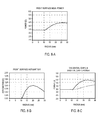
- Fig.2-A to Fig.2-C shows various characteristics of the front surface 108 of the lens 100 (ref. Fig.1 ) having the parameters listed in table 1.
- the back surface of the lens is a sphere with surface power of -8.3 D in 1.53 index.
- the ophthalmic lens element 100 provides a central zone 102 (ref. Fig.1 ) having a refracting power of -5.0 D and a peripheral zone 104 (ref. Fig.1 ) having a refracting power of around -4.5 D.
- the peripheral zone provides a plus power relative to the central zone.
- Fig.3-A illustrates another example of an ophthalmic lens element 200 according to an example not covered by the invention.
- the lens element 200 includes a front surface 108 having the same crown curvature as the lens 100 of Example 1, but a higher mean marginal curvature corresponding to an optical correction of +1.00 D in the peripheral zone relative to the central zone power.
- the back surface of this lens element 200 and the refracting power of the central zone 102 are the same as per Example 1.
- the front surface 108 uses the same mathematical description as Example 1, with a few parameters changed as listed in table 2.
- Fig.4-A to Fig.4-C show various characteristics of the front surface 108 of the lens 200.
- Fig.5-A illustrates an example of an ophthalmic lens element 300 in the 1.6 refractive index material including a front surface 108 having a marginal radius of curvature of 136.5 mm, and the same crown curvature as in Examples 1 and 2 corresponding to an optical correction of around +1.00 D in the peripheral zone 104 relative to the central zone 102 power. That is, in this example, the lens element 300 has a mean crown curvature of 3.40 D, and a mean marginal curvature of 4.39D at a radius of 20 mm from the lens centre.
- the front surface 108 uses the same mathematical description as Example 1 and Example 2 with a few parameters changed.
- the revised parameter values are as listed in table 3.
- Table 3 Parameter Value R 0 176.67 mm R 1 136.5 mm t 0 m 0 n 0.0000028 p 2.5 a 1.0 b 1.0
- Fig.6-A to Fig.6-C show various characteristics of the front surface 108 of the ophthalmic lens element 300.
- the ophthalmic lens element 300 has a larger blended region 106, as compared with ophthalmic lens element 100 (ref. Fig.1A ) and ophthalmic lens element 200 (ref. Fig.3A ).
- a larger blended region 106 helps to keep the peak value of astigmatism on the front surface 108 to around 0.75 D as compared to over 2.00 D in Example 2. It is envisaged that a lower peak value of astigmatism will make the ophthalmic lens element 300 easier for the wearer to adapt to.
- Fig.7-A illustrates another example of an ophthalmic lens element 400.
- the ophthalmic lens element 400 is manufactured from a 1.6 refractive index material and includes a front surface 108 having the same crown radius as the lens element 300 of Example 3, and a similar marginal curvature in the peripheral zone, corresponding to an optical correction of around +1.00 D in the peripheral zone 104 power relative to the central zone 102 power.
- the lens element 400 has a mean crown curvature of 3.40 D, and a mean marginal curvature of 4.28 D at a radius of 20 mm.
- the front surface 108 uses a finite element mesh surface mathematical description and has been designed by blending a central spherical surface having a surface power of 3.40 D with a peripheral spherical surface having a surface power of 4.28 D at a radius of 20 mm from the lens centre.
- the blending occurs between the radii of 11 mm and 50 mm.
- a C2 continuous extrapolation algorithm that minimises the surface curvature deviation from that of the marginal curvature, has been used to calculate a surface profile of the blend. It will be appreciated that it is not essential that a C2 extrapolation algorithm be used as any other suitable extrapolation algorithm may also be suitable.
- Fig.8-A to Fig.8-C show various characteristics of the front surface 108 of the lens element 300.
- the ophthalmic lens element 400 has a larger and nearly perfect spherical central region as compared to the previous examples.
- the larger and nearly perfect spherical central region helps to provide a clearer foveal vision to the wearer up to moderate values of eye rotation.
- Fig.8-D illustrates contour plots 402, 404, 406 for the surface tangential 402, and sagittal powers 404 as well as the surface astigmatism 406 (cylinder) of the front surface of the ophthalmic lens element 400.
- Fig.9-A illustrates an example of a segmented bifocal ophthalmic lens 500 element in 1.6 refractive index material including a front surface 108 having a crown curvature of 3.96 D, and a peripheral marginal curvature of 5.46 D at a radius of 20mm from the lens centre, corresponding to an optical correction of +1.50 D in the peripheral zone 104 relative to the central zone 102.
- the front surface 108 is made up of two rotationally symmetric spherical segments, namely a first centred round segment defining the central zone 102 and a second centred segment defining the peripheral zone 104.
- the first centred round segment has a radius ( R P1 ) of 14 mm which provides clear foveal vision up to the eye rotations of around 30°. It is to be appreciated that a different radius may be used without departing from the scope of the invention.
- Fig.10-A to Fig.10-C show various characteristics of the front surface 108 of the ophthalmic lens element 500.
- the second centred segment has zero surface astigmatism and in addition to providing an appropriate correction for peripheral vision, could also be used foveally for close work, such as reading.
- Fig.11 illustrates contour plot diagrams 602 (tangential), 604 (sagittal), 606 (cylinder) of the ophthalmic lens element of the invention including a central zone 102 having an asymmetric shape.
- the contour plots 602, 604, 606, illustrate the surface tangential and sagittal powers as well as surface astigmatism (cylinder) of the front surface of an ophthalmic lens element in 1.6 refractive index material.
- the surface characterised by the contour plots 602, 604, 606 have be derived as a new optimisation for the original surface characterised by the contour plots 402, 404, 406 (ref. Fig.8-D ) of the front surface of the ophthalmic lens element 400 with the symmetrical central zone 102 of Example 4.
- the central zone 102 is asymmetrical and provides a low level of astigmatism in an area 608 elongated towards the lower nasal side of the ophthalmic lens element to reduce the need for turning the head down during near work.
- the mean surface power in the peripheral zone at different radii from the optical centre of the lens element (as measured on the front surface of the lens), may not be constant throughout a particular radius.
- the peripheral power at 20mm from the optical centre of the lens element will be at least +0.50 D relative to the surface power at the optical centre of the central zone and inscribes, over each radii, the peripheral zone over an azimuthal extent of at least 270 degrees.
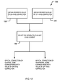
- Fig.12 is a simplified flow diagram for a method embodiment of the present invention. As shown, an embodiment of the method includes the step 1202 of obtaining a wearer's on-axis optical correction value. As explained previously, an on-axis optical correction value is a value required for clear central vision. The on-axis optical correction may be obtained using conventional measurement techniques and devices that known in the art.
- an off-axis optical correction value is an optical correction required to correct peripheral refractive errors in the wearer's eye, and thus for correcting myopia or hyperopia associated with a peripheral region of the retina of the wearer's eye.
- the off-axis optical correction may be obtained using conventional measurement techniques and devices known in the art, such as a Shin-Nippon autorefractor configured to measure peripheral refraction in a wearer's eye for a measurement axis aligned with a direction different to that of the wearer's primary direction of gaze.
- a Shin-Nippon autorefractor configured to measure peripheral refraction in a wearer's eye for a measurement axis aligned with a direction different to that of the wearer's primary direction of gaze.
- One suitable technique is described in David A. Atchison et al, 'Peripheral Refraction along the Horizontal and Vertical Visual Fields in Myopia' (2006) 46 Vision Research 1450 , the disclosures of which provide a skilled reader with an example a suitable device.
- an ophthalmic lens element is selected or designed in accordance with the measured values so as to include a central zone providing an optical correction corresponding with the on-axis correction; and a peripheral zone surrounding the central zone, the peripheral zone providing an optical correction corresponding with the off-axis correction.
- those zones may also have a shape and size that depends on the wearer's typical pattern of eye rotation.
- the selection or designing of the ophthalmic lens element may be performed by a system including a programmed computer equipped with suitable computer software.
- a system 1300 is depicted in Fig.13 .
- the system 1300 includes one or more input devices 1302-A, 1302A for accepting or obtaining optical correction values for a wearer.
- the optical correction values include a required value of on-axis optical correction for correcting myopia associated with the foveal region of the wearer's eye, and a required value of off-axis optical correction for correcting myopia or hyperopia associated with a peripheral region of the retina of the wearer's eye.
- the input devices 1302-A, 1302-B will typically include conventional devices for measuring the wearer's required on-axis optical correction and the wearer's a device required off-axis optical correction.
- One suitable input device for measuring a wearer's required off-axis optical correction is a Hartmann-Shack instrument configured to measure peripheral wave front aberrations in a wearer's eye for a measurement axis aligned with the direction of the wearer's preferred retinal location.
- Another suitable device is an open-field autorefractor, such as, for example, an autorefractor sold under the brand Shin-Nippon SRW-5000 or Shin Nippon NVision K5001.
- the system 1300 also includes a processor 1304 for accepting and processing the wearer's optical correction values to select or design an ophthalmic lens element according to the required values of on-axis and off-axis correction.
- the processor 1304 is a programmed computer equipped with suitable computer software. Examples of suitable computers include a desktop computer, a hand-held computer, a lap top computer, or a personal digital assistant.
- the input devices 1302-A, 1302-B may further include a device for accepting or obtaining head movement and eye movement characteristics for the wearer, such as, for example, an eye-tracking system of the type described in U.S. Pat. No. 6,827,443 ,.
- the processor 1304 will also include additional functionality to modify the size and shape of the central zone according to the head movement and eye movement characteristics of the wearer so that central zone provides an area of substantially uniform refracting power for supporting central vision throughout an angular range of eye rotations.
Landscapes
- Health & Medical Sciences (AREA)
- Ophthalmology & Optometry (AREA)
- Physics & Mathematics (AREA)
- General Health & Medical Sciences (AREA)
- General Physics & Mathematics (AREA)
- Optics & Photonics (AREA)
- Eyeglasses (AREA)
- Prostheses (AREA)
Claims (22)
- Ein Augenlinsenelement zur Korrektur von Kurzsichtigkeit im Auge eines Trägers, wobei das Linsenelement eine vordere Oberfläche, eine optische Achse und ein optisches Zentrum aufweist, wobei das Linsenelement Folgendes umfasst:(a) eine zentrale Zone, die eine erste optische Korrektur bereitstellt, um im Wesentlichen die mit der fovealen Region des Auges des Trägers assoziierte Kurzsichtigkeit zu korrigieren, wobei die zentrale Zone einen Bereich zum Unterstützen des zentralen Sehens über einen Winkelbereich der Augendrehung zum Betrachten der von der Sehachse entfernt liegenden Richtungen beinhaltet, wobei die zentrale Zone eine assymetrische Form um das optische Zentrum der zentralen Zone aufweist, um die asymmetrische Verteilung der Häufigkeit von Augendrehungen zu gestatten; und(b) eine periphere Zone, die die zentrale Zone umgibt, wobei die periphere Zone eine zweite optische Korrektur bereitstellt, um im Wesentlichen die mit der peripheren Region der Netzhaut des Auges des Trägers assoziierte Kurzsichtigkeit oder Übersichtigkeit zu korrigieren;wobei die erste optische Korrektur als eine erste Brechkraft angegeben ist und die zweite optische Korrektur als eine zweite Brechkraft angegeben ist und wobei die zweite Brechkraft eine Pluskraftkorrektur relativ zu der ersten Brechkraft bereitstellt, wobei die erste Brechkraft sich im optischen Zentrum des Augenlinsenelements befindet, wobei der Mittelwert der zweiten Brechkraft eine mittlere Brechkraft bei einem Radius von 20 mm von dem optischen Zentrum des Augenlinsenelements ist, gemessen an der vorderen Oberfläche des Linsenelements, und die periphere Zone über eine azimutale Weite von mindestens 270 Grad einbeschreibt, und wobei die zweite Brechkraft im Bereich von +0,50 D bis +2,0 D relativ zu der ersten Brechkraft liegt,
und wobei die zentrale Zone sich über eine Mischzone in die periphere Zone mischt. - Ein Augenlinsenelement gemäß Anspruch 1, wobei die Brechkraft in der zentralen Zone im Bereich von plan bis -6,00 D liegt.
- Ein Augenlinsenelement gemäß Anspruch 2, wobei die Brechkraft in der zentralen Zone im Bereich von plan bis -4,00 D liegt.
- Ein Augenlinsenelement gemäß einem der vorhergehenden Ansprüche, wobei die zentrale Zone eine Zone ist, die durch eine 0,5-D-Kontur eines Astigmatismus der vorderen Oberfläche begrenzt wird.
- Ein Augenlinsenelement gemäß einem der Ansprüche 1 bis 4, wobei innerhalb der zentralen Zone die Oberflächenkraft der vorderen Oberfläche um mehr als 0,5 D variiert.
- Ein Augenlinsenelement gemäß Anspruch 1 bis 5, wobei innerhalb der zentralen Zone die Oberflächenkraft der vorderen Oberfläche um weniger als 0,5 D variiert, und wobei die mittlere Brechkraft der peripheren Zone im Bereich von +0,50 D bis +2,0 D relativ zu der Brechkraft im optischen Zentrum der zentralen Zone liegt.
- Ein Augenlinsenelement gemäß Anspruch 1 bis 5, wobei innerhalb der zentralen Zone die Oberflächenkraft der vorderen Oberfläche um weniger als 0,5 D variiert, und wobei die mittlere Brechkraft der peripheren Zone bei einem Radius von 20 mm von dem optischen Zentrum, gemessen auf der vorderen Oberfläche der Linse, mindestens +0,50 D relativ zu der Brechkraft im optischen Zentrum der zentralen Zone beträgt und die periphere Zone über eine azimutale Weite von mindestens 270 Grad einbeschreibt.
- Ein Augenlinsenelement gemäß Anspruch 1 bis 5, wobei innerhalb der zentralen Zone die Oberflächenkraft der vorderen Oberfläche um weniger als 0,5 D variiert, und wobei die mittlere Brechkraft der peripheren Zone bei einem Radius von 20 mm von dem optischen Zentrum des Linsenelements, gemessen auf der vorderen Oberfläche der Linse, mindestens +1,00 D relativ zu der Brechkraft im optischen Zentrum der zentralen Zone beträgt und die periphere Zone über eine azimutale Weite von mindestens 270 Grad einbeschreibt.
- Ein Augenlinsenelement gemäß Anspruch 1 bis 5, wobei innerhalb der zentralen Zone die Oberflächenkraft der vorderen Oberfläche um weniger als 0,5 D variiert, und wobei die mittlere Brechkraft der peripheren Zone bei einem Radius von 20 mm von dem optischen Zentrum des Linsenelements, gemessen auf der vorderen Oberfläche der Linse, mindestens +1,50 D relativ zu der Brechkraft im optischen Zentrum der zentralen Zone beträgt und die periphere Zone über eine azimutale Weite von mindestens 270 Grad einbeschreibt.
- Ein Augenlinsenelement gemäß Anspruch 1 bis 5, wobei innerhalb der zentralen Zone die Oberflächenkraft der vorderen Oberfläche um weniger als 0,5 D variiert, und wobei die mittlere Brechkraft der peripheren Zone bei einem Radius von 20 mm von dem optischen Zentrum des Linsenelements, gemessen auf der vorderen Oberfläche der Linse, mindestens +2,00 D relativ zu der Brechkraft im optischen Zentrum der zentralen Zone beträgt und die periphere Zone über eine azimutale Weite von mindestens 270 Grad einbeschreibt.
- Ein Augenlinsenelement gemäß Anspruch 1 bis 5, wobei innerhalb der zentralen Zone die Oberflächenkraft der vorderen Oberfläche um weniger als 0,5 D variiert, und wobei die mittlere Oberflächenkraft der peripheren Zone bei einem Radius von 20 mm von dem optischen Zentrum des Linsenelements, gemessen auf der vorderen Oberfläche der Linse, mindestens +0,50 D relativ zu der Oberflächenkraft im optischen Zentrum der zentralen Zone beträgt und die periphere Zone über eine azimutale Weite von mindestens 270 Grad einbeschreibt.
- Ein Augenlinsenelement gemäß Anspruch 1 bis 5, wobei innerhalb der zentralen Zone die Oberflächenkraft der vorderen Oberfläche um weniger als 0,5 D variiert, und wobei die mittlere Oberflächenkraft der peripheren Zone bei einem Radius von 20 mm von dem optischen Zentrum des Linsenelements, gemessen auf der vorderen Oberfläche der Linse, mindestens +1,00 D relativ zu der Oberflächenkraft im optischen Zentrum der zentralen Zone beträgt und die periphere Zone über eine azimutale Weite von mindestens 270 Grad einbeschreibt
- Ein Augenlinsenelement gemäß Anspruch 1 bis 5, wobei innerhalb der zentralen Zone die Oberflächenkraft der vorderen Oberfläche um weniger als 0,5 D variiert, und wobei die mittlere Oberflächenkraft der peripheren Zone bei einem Radius von 20 mm von dem optischen Zentrum des Linsenelements, gemessen auf der vorderen Oberfläche der Linse, mindestens +1,50 D relativ zu der Oberflächenkraft im optischen Zentrum der zentralen Zone beträgt und die periphere Zone über eine azimutale Weite von mindestens 270 Grad einbeschreibt
- Ein Augenlinsenelement gemäß Anspruch 1 bis 5, wobei innerhalb der zentralen Zone die Oberflächenkraft der vorderen Oberfläche um weniger als 0,5 D variiert, und wobei die mittlere Oberflächenkraft der peripheren Zone bei einem Radius von 20 mm von dem optischen Zentrum des Linsenelements, gemessen auf der vorderen Oberfläche der Linse, mindestens +2,00 D relativ zu der Oberflächenkraft im optischen Zentrum der zentralen Zone beträgt und die periphere Zone über eine azimutale Weite von mindestens 270 Grad einbeschreibt
- Ein Augenlinsenelement gemäß Anspruch 1, wobei sich die Mischzone von der Grenze der zentralen Zone radial nach außen und in die periphere Zone hinein erstreckt, und wobei die radiale Weite der Mischzone geringer ist als der Radius der zentralen Zone für klaren fovealen Visus.
- Ein Augenlinsenelement gemäß einem der Ansprüche 1 bis 15, wobei das Linsenelement einen halbfertigen Brillenlinsenrohling oder eine Brillenlinsenscheibe beinhaltet.
- Ein Verfahren zum Konstruieren eines Augenlinsenelements zum Korrigieren von Kurzsichtigkeit im Auge eines Trägers, wobei das Linsenelement eine vordere Oberfläche, eine optische Achse und ein optisches Zentrum aufweist, wobei das Verfahren Folgendes umfasst:(a) das Erhalten für den Träger:(i) eines benötigten Werts für die achsenparallele optische Korrektur, wobei es sich bei der achsenparallelen optischen Korrektur um das Korrigieren der mit der fovealen Region des Auges des Trägers assoziierten Kurzsichtigkeit handelt; und(ii) eines benötigten Werts für die nicht achsenparallele optische Korrektur, wobei es sich bei der nicht achsenparallelen optischen Korrektur um das Korrigieren der mit einer peripheren Region der Netzhaut des Auges des Trägers assoziierten Kurzsichtigkeit oder Übersichtigkeit handelt;(b) das Konstruieren des Augenlinsenelements gemäß den Werten der achsenparallelen und nicht achsenparallelen Korrektur, wobei das Augenlinsenelement Folgendes umfasst:wobei die erste optische Korrektur als eine erste Brechkraft angegeben ist und die zweite optische Korrektur als eine zweite Brechkraft angegeben ist und wobei die zweite Brechkraft eine Pluskraftkorrektur relativ zu der ersten Brechkraft bereitstellt.(i) eine zentrale Zone, die eine erste optische Korrektur entsprechend der achsenparallelen optischen Korrektur bereitstellt, wobei die zentrale Zone einen Bereich zum Unterstützen des zentralen Sehens über einen Winkelbereich der Augendrehung zum Betrachten der von der Sehachse entfernt liegenden Richtungen beinhaltet; und(ii) eine periphere Zone, die die zentrale Zone umgibt, wobei die periphere Zone eine zweite optische Korrektur entsprechend der nicht achsenparallelen optischen Korrektur bereitstellt;
- Ein Verfahren gemäß Anspruch 17, das ferner Folgendes umfasst:(c) das Bestimmen der Kopfbewegungs- und Augenbewegungseigenschaften des Trägers; und(d) das Dimensionieren und Formen der zentralen Zone gemäß den Kopfbewegungs- und Augenbewegungseigenschaften des Trägers, so dass die zentrale Zone einen Bereich von im Wesentlichen gleichförmiger Brechkraft bereitstellt, um das zentrale Sehen über einem gesamten Winkelbereich von Augendrehungen zu unterstützen.
- Ein System zum Abgeben oder Konstruieren eines Augenlinsenelements zur Korrektur von Kurzsichtigkeit im Auge eines Trägers, wobei das Linsenelement eine vordere Oberfläche, eine optische Achse und ein optisches Zentrum aufweist, wobei das Linsenelement Folgendes umfasst:(a) ein Eingabegerät zum Akzeptieren oder Erhalten von optischen Korrekturwerten für einen Träger, wobei die optischen Korrekturwerte Folgendes umfassen:(i) einen benötigten Wert für die achsenparallele optische Korrektur, wobei es sich bei der achsenparallelen optischen Korrektur um das Korrigieren der mit der fovealen Region des Auges des Trägers assoziierten Kurzsichtigkeit handelt; und(ii) einen benötigten Wert für die nicht achsenparallele optische Korrektur, wobei es sich bei der nicht achsenparallelen optischen Korrektur um das Korrigieren der mit einer peripheren Region der Netzhaut des Auges des Trägers assoziierten Kurzsichtigkeit oder Übersichtigkeit handelt; und(b) einen Prozessor zum Verarbeiten der optischen Korrekturwerte, um ein Augenlinsenelement gemäß den Werten der achsenprallelen und nicht achsenparallelen Korrektur auszuwählen oder zu konstruieren, wobei das Augenlinsenelement Folgendes umfasst:wobei die erste optische Korrektur als eine erste Brechkraft angegeben ist und die zweite optische Korrektur als eine zweite Brechkraft angegeben ist, und wobei die zweite Brechkraft eine Pluskraftkorrektur relativ zu der ersten Brechkraft bereitstellt.(i) eine zentrale Zone, die eine erste optische Korrektur entsprechend der achsenparallelen optischen Korrektur bereitstellt, wobei die zentrale Zone einen Bereich zum Unterstützen des zentralen Sehens über einen Winkelbereich der Augendrehung zum Betrachten der von der Sehachse entfernt liegenden Richtungen beinhaltet; und(ii) eine periphere Zone, die die zentrale Zone umgibt, wobei die periphere Zone eine zweite optische Korrektur entsprechend der nicht achsenparallelen optischen Korrektur bereitstellt;
- Ein System gemäß Anspruch 19, das ferner Folgendes umfasst:(a) ein Eingabegerät zum Akzeptieren oder Erhalten von Kopfbewegungs- und Augenbewegungseigenschften für den Träger; und(b) den Prozessor zum Modifizieren der Größe und Form der zentralen Zone gemäß den Kopfbewegungs- und Augenbewegungseigenschaften des Trägers, so dass die zentrale Zone einen Bereich von im Wesentlichen gleichförmiger Brechkraft bereitstellt, um das zentrale Sehen über einem gesamten Winkelbereich von Augendrehungen zu unterstützen.
- Ein Computer-Softwareprogramm, das einen Computer zum Ausführen eines Verfahrens gemäß einem der Ansprüche 17 oder 18 veranlasst.
- Ein computerlesbarer Speicher, der ein Computer-Softwareprogramm gemäß Anspruch 21 enthält.
Applications Claiming Priority (3)
| Application Number | Priority Date | Filing Date | Title |
|---|---|---|---|
| AU2005905621A AU2005905621A0 (en) | 2005-10-12 | Opthalmic lens element | |
| AU2005906150A AU2005906150A0 (en) | 2005-11-07 | Ophthalmic lens element | |
| PCT/AU2006/001505 WO2007041796A1 (en) | 2005-10-12 | 2006-10-12 | Ophthalmic lens element for myopia correction |
Publications (3)
| Publication Number | Publication Date |
|---|---|
| EP1934648A1 EP1934648A1 (de) | 2008-06-25 |
| EP1934648A4 EP1934648A4 (de) | 2010-09-22 |
| EP1934648B1 true EP1934648B1 (de) | 2016-08-03 |
Family
ID=37942230
Family Applications (1)
| Application Number | Title | Priority Date | Filing Date |
|---|---|---|---|
| EP06790375.7A Active EP1934648B1 (de) | 2005-10-12 | 2006-10-12 | Ophthalmisches linsenelement zur korrektur von kurzsichtigkeit |
Country Status (11)
| Country | Link |
|---|---|
| US (1) | US7862171B2 (de) |
| EP (1) | EP1934648B1 (de) |
| JP (3) | JP2009511962A (de) |
| KR (1) | KR101302317B1 (de) |
| CN (1) | CN101317120B (de) |
| AU (1) | AU2006301940B2 (de) |
| BR (1) | BRPI0617356B1 (de) |
| CA (1) | CA2626050C (de) |
| ES (1) | ES2599510T3 (de) |
| MY (1) | MY147505A (de) |
| WO (1) | WO2007041796A1 (de) |
Cited By (3)
| Publication number | Priority date | Publication date | Assignee | Title |
|---|---|---|---|---|
| EP4198615A1 (de) * | 2021-12-16 | 2023-06-21 | Essilor International | Verfahren zur bestimmung eines brillenglases |
| DE102023110431B3 (de) | 2023-04-24 | 2024-10-10 | Rodenstock Gmbh | Reduktion der Progression von Myopie mit angepasstem Wirkungsbereich, Verfahren, Serie von Brillengläsern, Vorrichtung, Computerprogrammerzeugnis sowie Verwendung |
| DE102023110569B3 (de) | 2023-04-25 | 2024-10-31 | Rodenstock Gmbh | Brillenglas zum Myopie Management mit dualer Progressionskontrolle, Verfahren sowie Verwendung |
Families Citing this family (112)
| Publication number | Priority date | Publication date | Assignee | Title |
|---|---|---|---|---|
| EP3391854A1 (de) * | 2006-01-12 | 2018-10-24 | Brien Holden Vision Institute | Verfahren und vorrichtung zur steuerung der peripheren bildposition zur verminderung von myopieprogression |
| WO2007146673A2 (en) | 2006-06-08 | 2007-12-21 | Vision Crc Limited | Means for controlling the progression of myopia |
| BRPI0716719B1 (pt) | 2006-09-15 | 2018-07-03 | Carl Zeiss Vision Australia Holdings Limited | Elemento de lente oftálmica, série de elementos de lente oftálmica, e, método de preparar ou projetar um elemento lente oftálmica |
| KR20150015046A (ko) | 2006-10-10 | 2015-02-09 | 노파르티스 아게 | 광학적으로 조절되는 주변 부분을 갖는 렌즈 및 상기 렌즈의 설계 및 제조 방법 |
| FR2910645B1 (fr) * | 2006-12-22 | 2009-07-03 | Essilor Int | Procede de determination d'une lentille ophtalmique. |
| FR2912820B1 (fr) * | 2007-02-15 | 2009-05-15 | Essilor Int | Realisation d'un element ophtalmique adapte pour les visions foveale et peripherique |
| CN101675372B (zh) * | 2007-03-09 | 2012-12-26 | 奥克兰联合服务有限公司 | 接触镜片和方法 |
| US7637612B2 (en) * | 2007-05-21 | 2009-12-29 | Johnson & Johnson Vision Care, Inc. | Ophthalmic lenses for prevention of myopia progression |
| US8690319B2 (en) * | 2007-05-21 | 2014-04-08 | Johnson & Johnson Vision Care, Inc. | Ophthalmic lenses for prevention of myopia progression |
| FR2916864B1 (fr) | 2007-05-31 | 2010-01-08 | Essilor Int | Verre ophtalmique progressif de correction de myopie et procede de realisation d'un tel verre |
| TWI467266B (zh) * | 2007-10-23 | 2015-01-01 | 視覺Crc有限公司 | 眼科鏡片元件 |
| US8057034B2 (en) * | 2007-10-26 | 2011-11-15 | Brien Holden Vision Institute | Methods and apparatuses for enhancing peripheral vision |
| SG10201506615RA (en) | 2008-04-18 | 2015-10-29 | Holden Brien Vision Inst | Myopia control means |
| AU2015249098A1 (en) * | 2008-04-18 | 2015-11-12 | Brien Holden Vision Institute | Myopia control means |
| US8684520B2 (en) | 2008-08-11 | 2014-04-01 | Novartis Ag | Lens design and method for preventing or slowing the progression of myopia |
| AU2013231016B2 (en) * | 2008-08-11 | 2015-07-16 | Alcon Inc. | A Lens Design and Method for Preventing or Slowing the Progression of Myopia |
| FR2936879B1 (fr) * | 2008-10-07 | 2011-03-11 | Essilor Int | Verre ophtalmique corrigeant la vision foveale et la vision peripherique. |
| DE102009053467B4 (de) | 2008-11-14 | 2018-01-18 | Rodenstock Gmbh | Ophthalmische Linse mit peripherer Brechkraftvariation |
| MX2011006600A (es) * | 2008-12-19 | 2011-06-30 | Novartis Ag | Coreccion de desenfoque periferico de un ojo y control del desarrollo del error de refraccion. |
| EP3552587B1 (de) | 2008-12-22 | 2026-03-18 | Medical College of Wisconsin, Inc. | Vorrichtung zur begrenzung des augenlängenwachstums |
| ES2345027B1 (es) * | 2009-03-12 | 2011-09-30 | Universidad De Murcia | Dispositivo de correccion optica de refraccion en la retina periferica de manera asimetrica para el control de la progresion de la miopia. |
| JP5753160B2 (ja) * | 2009-05-04 | 2015-07-22 | クーパーヴィジョン インターナショナル ホウルディング カンパニー リミテッド パートナーシップ | 調節ラグの測定値に基づいてコンタクトレンズを供与する方法 |
| WO2010129465A1 (en) | 2009-05-04 | 2010-11-11 | Cooper Vision International Holding Company, Lp | Ophthalmic lenses and reduction of accommodative error |
| MY179129A (en) * | 2009-05-04 | 2020-10-28 | Coopervision Int Ltd | Small optic zone contact lenses and methods |
| CN102483526B (zh) | 2009-06-25 | 2013-11-13 | 庄臣及庄臣视力保护公司 | 近视控制镜片的设计 |
| US8128223B2 (en) | 2009-10-08 | 2012-03-06 | Crt Technology, Inc. | Methods and therapeutic optical devices for regulation of astigmatism |
| CN102472899B (zh) * | 2009-10-22 | 2013-11-06 | 库柏维景国际控股公司 | 预防或减慢近视或远视的发展的隐形眼镜组和方法 |
| CA2779675C (en) | 2009-11-09 | 2017-07-25 | Saulius Raymond Varnas | Ophthalmic lens element |
| US8246167B2 (en) | 2009-12-17 | 2012-08-21 | Crt Technology, Inc. | Systems and methods for the regulation of emerging myopia |
| ES2406381B1 (es) * | 2010-05-11 | 2014-04-25 | Jaume Paune Fabre | Lente de contacto para el tratamiento de la miopía. |
| ES2421464B1 (es) * | 2010-06-04 | 2014-11-17 | Tiedra Farmaceutica, S.L. | Lente de contacto blanda correctora-estabilizadora de la miopia |
| MY166501A (en) | 2010-07-30 | 2018-06-27 | Coopervision Int Holding Co Lp | Ophthalmic lens molds, ophthalmic lenses molded therein, and related methods |
| JP2013537317A (ja) * | 2010-09-13 | 2013-09-30 | ザ ホンコン ポリテクニック ユニヴァーシティー | 近視の進行を遅らせる方法及びシステム |
| JP2012233959A (ja) | 2011-04-28 | 2012-11-29 | Seiko Epson Corp | 眼鏡用レンズ、眼鏡、眼鏡レンズの設計方法、及び設計装置 |
| CN104094165B (zh) | 2011-06-15 | 2017-08-25 | 文森尔林技术公司 | 治疗近视加深的方法 |
| WO2013015743A1 (en) * | 2011-07-27 | 2013-01-31 | National University Of Singapore | Optical lens for slowing myopia progression |
| CN103930821B (zh) * | 2011-11-16 | 2016-08-24 | 埃西勒国际通用光学公司 | 用于提供眼镜片的光学系统的方法和用于制造眼镜片的方法 |
| WO2013072065A1 (en) * | 2011-11-16 | 2013-05-23 | Essilor International, (Compagnie Générale d'Optique) | Method for providing an optical system of an ophthalmic spectacle lens and method for manufacturing an ophthalmic spectacle lens |
| CN103930823B (zh) * | 2011-11-16 | 2016-06-22 | 埃西勒国际通用光学公司 | 用于提供眼镜片的光学系统的方法和用于制造眼镜片的方法 |
| KR20140138756A (ko) * | 2012-02-21 | 2014-12-04 | 퀸스랜드 유니버시티 오브 테크놀로지 | 근시 진행의 지연 및/또는 근시 또는 근시-관련 질환이나 상태의 치료 또는 예방 |
| TWI588560B (zh) | 2012-04-05 | 2017-06-21 | 布萊恩荷登視覺協會 | 用於屈光不正之鏡片、裝置、方法及系統 |
| WO2014019968A1 (en) | 2012-07-31 | 2014-02-06 | Essilor International (Compagnie Generale D'optique) | Progressive ophthalmic lens |
| US11126040B2 (en) | 2012-09-30 | 2021-09-21 | Optica Amuka (A.A.) Ltd. | Electrically-tunable lenses and lens systems |
| US9201250B2 (en) | 2012-10-17 | 2015-12-01 | Brien Holden Vision Institute | Lenses, devices, methods and systems for refractive error |
| SG11201502115RA (en) | 2012-10-17 | 2015-05-28 | Holden Brien Vision Inst | Lenses, devices, methods and systems for refractive error |
| US9265458B2 (en) | 2012-12-04 | 2016-02-23 | Sync-Think, Inc. | Application of smooth pursuit cognitive testing paradigms to clinical drug development |
| US8998408B2 (en) * | 2013-01-30 | 2015-04-07 | Johnson & Johnson Vision Care, Inc. | Asymmetric lens design and method for preventing and/or slowing myopia progression |
| ES2554119T3 (es) | 2013-03-01 | 2015-12-16 | Essilor International (Compagnie Générale d'Optique) | Método para optimizar el prisma postural de una lente oftálmica |
| US9380976B2 (en) | 2013-03-11 | 2016-07-05 | Sync-Think, Inc. | Optical neuroinformatics |
| WO2014184399A1 (es) * | 2013-05-15 | 2014-11-20 | Tiedra Farmacéutica, S.L. | Lente de contacto blanda correctora-estabilizadora de la miopía |
| RU2541819C2 (ru) * | 2013-05-24 | 2015-02-20 | Рашид Адыгамович Ибатулин | Способ тренировки аккомодации, профилактики и/или лечения прогрессирующей близорукости и устройство для его осуществления |
| BR112016017990B1 (pt) | 2014-02-04 | 2022-06-14 | Crt Technology, Inc | Lente de contato multifuncional |
| EP2923826B1 (de) * | 2014-03-28 | 2018-11-07 | Essilor International | Ophthalmische Linse und Herstellungsverfahren einer solchen Linse |
| US10288903B2 (en) | 2014-06-04 | 2019-05-14 | Hoya Lens Thailand Ltd. | Progressive addition lens |
| CN106461976B (zh) * | 2014-06-04 | 2019-12-06 | 豪雅镜片泰国有限公司 | 渐进屈光力镜片 |
| JP6649901B2 (ja) | 2014-06-05 | 2020-02-19 | オプティカ アムカ(エー.エー.)リミテッド | 動的レンズの制御 |
| US10061143B2 (en) | 2014-08-29 | 2018-08-28 | Johnson & Johnson Vision Care, Inc. | Multifocal lens design for preventing and/or slowing myopia progression |
| US9733494B2 (en) | 2014-08-29 | 2017-08-15 | Johnson & Johnson Vision Care, Inc. | Free form lens design and method for preventing and/or slowing myopia progression |
| CN104749791A (zh) * | 2015-01-15 | 2015-07-01 | 中山大学中山眼科中心 | 一种光学聚焦调控镜片及光学聚焦调控方法 |
| KR101578327B1 (ko) * | 2015-06-04 | 2015-12-16 | 구오섭 | 노안용 콘택트렌즈 |
| CN105137611B (zh) * | 2015-07-13 | 2018-03-23 | 苏州苏大明世光学股份有限公司 | 一种超环面散光眼镜片及其制备方法 |
| JP6931349B2 (ja) * | 2015-07-24 | 2021-09-01 | 愛博諾徳(北京)医療科技股▲フン▼有限公司Eyebright Medical Technology(Beijing)Co.,Ltd. | 視力矯正用レンズおよび視力矯正用レンズの作成方法 |
| JP2016026324A (ja) * | 2015-10-05 | 2016-02-12 | イーエイチエス レンズ フィリピン インク | 眼鏡用レンズ、眼鏡、眼鏡レンズの設計方法、及び設計装置 |
| CN108351531B (zh) * | 2015-11-13 | 2021-04-30 | 依视路国际公司 | 畸变管理得到改善的镜片 |
| CN105866978B (zh) * | 2016-06-21 | 2019-05-03 | 温州众视福眼镜镜片厂(普通合伙) | 一种近视太阳镜片及加工该镜片的模具 |
| SG11201900867UA (en) | 2016-08-01 | 2019-02-27 | Jay Neitz | Ophthalmic lenses for treating myopia |
| EP3625620B1 (de) | 2017-05-08 | 2025-09-10 | SIGHTGLASS VISION, Inc. | Herstellungsverfahren von kontaktlinsen zur reduzierung von myopie |
| US11953764B2 (en) | 2017-07-10 | 2024-04-09 | Optica Amuka (A.A.) Ltd. | Tunable lenses with enhanced performance features |
| TWI636296B (zh) * | 2017-08-28 | 2018-09-21 | 精華光學股份有限公司 | 視力矯正用光學鏡片 |
| US11789292B2 (en) | 2018-01-22 | 2023-10-17 | Johnson & Johnson Vision Care, Inc. | Ophthalmic lens with an optically non-coaxial zone for myopia control |
| US10901237B2 (en) * | 2018-01-22 | 2021-01-26 | Johnson & Johnson Vision Care, Inc. | Ophthalmic lens with an optically non-coaxial zone for myopia control |
| US11768386B2 (en) | 2018-01-22 | 2023-09-26 | Johnson & Johnson Vision Care, Inc. | Ophthalmic lens with an optically non-coaxial zone for myopia control |
| US10884264B2 (en) | 2018-01-30 | 2021-01-05 | Sightglass Vision, Inc. | Ophthalmic lenses with light scattering for treating myopia |
| BR202019004173Y1 (pt) | 2018-03-01 | 2024-02-20 | Essilor International | Dispositivo óptico |
| CN216310444U (zh) | 2018-03-01 | 2022-04-15 | 依视路国际公司 | 镜片元件 |
| US11378818B2 (en) | 2018-03-01 | 2022-07-05 | Essilor International | Lens element |
| US10921612B2 (en) | 2018-03-29 | 2021-02-16 | Reopia Optics, Llc. | Spectacles and associated methods for presbyopia treatment and myopia progression control |
| US11681161B2 (en) | 2018-03-29 | 2023-06-20 | Reopia Optics, Inc. | Anti-myopia-progression spectacles and associated methods |
| US11947197B2 (en) | 2018-03-29 | 2024-04-02 | Reopia Optics, Inc. | Spectacles for presbyopia treatment and myopia progression control and associated methods |
| NZ771500A (en) * | 2018-07-12 | 2023-05-26 | Sightglass Vision Inc | Methods and devices for reducing myopia in children |
| WO2020149213A1 (ja) | 2019-01-16 | 2020-07-23 | 株式会社トプコン | 眼科装置 |
| US12416818B2 (en) | 2019-03-01 | 2025-09-16 | Sightglass Vision, Inc. | Ophthalmic lenses for reducing myopic progression and methods of making the same |
| IL322041A (en) | 2019-04-23 | 2025-09-01 | Sightglass Vision Inc | Ophthalmic lenses with dynamic optical properties to reduce the development of myopia |
| CN109946849B (zh) * | 2019-04-25 | 2024-11-26 | 江苏承启光电科技有限公司 | 光学框架眼镜 |
| JP7496142B2 (ja) * | 2019-06-02 | 2024-06-06 | オプティカ アムカ(エー.エー.)リミテッド | 近視の治療のための電気的に調整可能な視力補助具 |
| JP7657519B2 (ja) * | 2019-06-25 | 2025-04-07 | ホヤ レンズ タイランド リミテッド | 眼鏡レンズおよびその設計方法 |
| JP7217676B2 (ja) * | 2019-06-25 | 2023-02-03 | ホヤ レンズ タイランド リミテッド | 眼鏡レンズおよびその設計方法 |
| EP3761104A1 (de) * | 2019-07-04 | 2021-01-06 | Essilor International | Optisches system |
| CN119916591A (zh) * | 2019-08-23 | 2025-05-02 | 华柏恩视觉研究中心有限公司 | 用于减少、最小化和/或消除失焦光对聚焦图像的干扰的眼科镜片 |
| CN114391121B (zh) * | 2019-09-12 | 2024-03-26 | 香港理工大学 | 用于延缓近视进展的镜片和方法 |
| EP4006627B1 (de) | 2020-11-26 | 2023-07-12 | Carl Zeiss Vision International GmbH | Brillenglas design, brillenglas kit und herstellungsmethode eines brillenglases |
| EP4006626A1 (de) | 2020-11-26 | 2022-06-01 | Carl Zeiss Vision International GmbH | Brillenglas design, brillenglas kit und herstellungsmethode eines brillenglases |
| EP4006624B1 (de) | 2020-11-26 | 2024-04-24 | Carl Zeiss Vision International GmbH | Brillenglas design, brillenglas kit und herstllungsmethod eines brillenglases zur behandlung der fortschreitenden kurzsichtigkeit |
| JP2023550996A (ja) | 2020-11-27 | 2023-12-06 | エシロール・アンテルナシオナル | レンズ要素 |
| IL279439B (en) * | 2020-12-14 | 2022-01-01 | Shamir Optical Ind Ltd | Lens system for anisometropy control and method therefor |
| US12585141B2 (en) * | 2020-12-23 | 2026-03-24 | Essilor International | Optical lens |
| CN115137623A (zh) * | 2021-03-31 | 2022-10-04 | 刘振灏 | 一种训练眼镜、训练系统及其训练方法 |
| ES2998813T3 (en) * | 2021-04-29 | 2025-02-21 | Coopervision Int Ltd | Lens sets for use in preventing or slowing the development or progression of myopia and related methods |
| WO2022231624A1 (en) | 2021-04-30 | 2022-11-03 | Carl Zeiss Vision Inc. | A progressive spectacle lens |
| AU2022270705A1 (en) | 2021-05-06 | 2023-11-30 | Ohio State Innovation Foundation | Myopia control contact lens |
| EP4089473A1 (de) | 2021-05-10 | 2022-11-16 | Carl Zeiss Vision International GmbH | Brillenglasdesign, brillenglas-kit, verfahren zur herstellung von brillenglas und verfahren zur bereitstellung eines brillenglasdesigns |
| JP7177959B1 (ja) * | 2021-09-15 | 2022-11-24 | ホヤ レンズ タイランド リミテッド | 眼鏡レンズ |
| US12174460B2 (en) | 2021-10-07 | 2024-12-24 | Indizen Optical Technologies of America, LLC | Ophthalmic lenses for myopia reduction |
| GB2615863B (en) * | 2021-12-21 | 2024-05-22 | Coopervision Int Ltd | Contact lenses and methods relating thereto |
| WO2023139348A1 (en) * | 2022-01-19 | 2023-07-27 | Coopervision International Limited | Contact lenses and methods relating thereto |
| CN117233962A (zh) * | 2022-06-08 | 2023-12-15 | Oppo广东移动通信有限公司 | 镜片模组及增强现实设备 |
| EP4292798A1 (de) | 2022-06-14 | 2023-12-20 | Carl Zeiss Vision International GmbH | Verfahren zum bereitsstellen von lichtbrechenden mikrostrukturen auf einer brillenglasoberfläche und brillenglasdesign |
| EP4390517A1 (de) * | 2022-12-23 | 2024-06-26 | Carl Zeiss Vision International GmbH | Brillenglasdesigndaten und verfahren zur herstellung eines brillenglases |
| EP4390516A1 (de) | 2022-12-23 | 2024-06-26 | Carl Zeiss Vision International GmbH | Brillenglasdesigndaten und verfahren zur herstellung eines brillenglases |
| JP2025002298A (ja) * | 2023-06-22 | 2025-01-09 | ホヤ レンズ タイランド リミテッド | 眼鏡、および、眼鏡レンズ |
| CN119065148B (zh) * | 2023-08-25 | 2025-11-28 | 北京大学人民医院 | 近视防控镜片和用于防控近视的眼镜 |
| WO2025184865A1 (en) | 2024-03-07 | 2025-09-12 | Carl Zeiss Vision International Gmbh | Spectacle lens and kit |
Citations (3)
| Publication number | Priority date | Publication date | Assignee | Title |
|---|---|---|---|---|
| US5054904A (en) * | 1989-05-22 | 1991-10-08 | Bristol Alexander C | Aspheric lens blank |
| US20020021410A1 (en) * | 2000-08-17 | 2002-02-21 | Ming Ye | Soft translating contact lens for presbyopia |
| WO2005085937A1 (de) * | 2004-03-03 | 2005-09-15 | Rodenstock Gmbh | Brillenglas mit einem tragrand |
Family Cites Families (26)
| Publication number | Priority date | Publication date | Assignee | Title |
|---|---|---|---|---|
| US1955047A (en) * | 1931-12-03 | 1934-04-17 | Howard D Beach | Spectacle lens |
| US4525043A (en) * | 1977-11-11 | 1985-06-25 | Leonard Bronstein | Contact lens |
| AU601779B2 (en) | 1986-11-21 | 1990-09-20 | Sola International Holdings Ltd | Cross-linkable casting composition |
| US4912155A (en) | 1987-02-27 | 1990-03-27 | Ethyl Corporation | Antioxidant aromatic fluorophosphites |
| US4954591A (en) | 1987-11-06 | 1990-09-04 | Pilkington Visioncare Holdings, Inc. | Abrasion resistant radiation curable coating for polycarbonate article |
| FR2642854B1 (fr) * | 1989-02-03 | 1991-05-03 | Essilor Int | Lentille optique a vision simultanee pour la correction de la presbytie |
| AU637892B2 (en) | 1990-04-12 | 1993-06-10 | Otis Elevator Company | Elevator dynamic channeling dispatching for up-peak period |
| US4968815A (en) | 1990-04-16 | 1990-11-06 | Merck & Co., Inc. | Synthesis of (S)-3-(thien-2-ylthio)butyric acid analogs |
| FR2666220B1 (fr) | 1990-09-04 | 1996-03-01 | Domilens Lab | Implant intra-oculaire pour correction de la myopie. |
| CN2098696U (zh) * | 1991-02-23 | 1992-03-11 | 刘瓒澄 | 双抛物面超薄眼镜片 |
| US5349395A (en) * | 1991-08-23 | 1994-09-20 | Nick Stoyan | Multiple focus corneal contact lens and method for treating myopia |
| AU665124B2 (en) | 1992-11-16 | 1995-12-14 | Sola International Holdings Ltd | Cross-linkable polymeric composition |
| AU5058293A (en) | 1992-11-16 | 1994-05-26 | Sola International Holdings Ltd | Cross-linkable polymeric composition |
| US5526071A (en) * | 1993-03-31 | 1996-06-11 | Permeable Technologies, Inc. | Multifocal contact lens and method for preparing |
| JPH07294859A (ja) * | 1994-04-25 | 1995-11-10 | Tokai Kogaku Kk | 累進多焦点レンズ |
| AUPM970294A0 (en) | 1994-11-28 | 1994-12-22 | Queensland University Of Technology | An optical control method |
| US5695509A (en) * | 1995-03-10 | 1997-12-09 | El Hage; Sami G. | Aspherical optical molds for continuous reshaping the cornea based on topographical analysis |
| JP3196877B2 (ja) * | 1995-04-18 | 2001-08-06 | ホーヤ株式会社 | 累進多焦点レンズ |
| US5704692A (en) | 1995-08-01 | 1998-01-06 | Rockwell Heavy Vehicles Systems, Inc. | Method of welding a sensor bracket to an axle |
| US6457826B1 (en) * | 1998-08-06 | 2002-10-01 | John B. W. Lett | Multifocal aspheric lens |
| AUPQ591800A0 (en) | 2000-02-25 | 2000-03-23 | Sola International Holdings Ltd | System for prescribing and/or dispensing ophthalmic lenses |
| US6752499B2 (en) * | 2001-07-11 | 2004-06-22 | Thomas A. Aller | Myopia progression control using bifocal contact lenses |
| AUPR949101A0 (en) * | 2001-12-14 | 2002-01-24 | Sola International Holdings Ltd | Method for prescribing and/or dispensing ophthalmic lenses |
| BRPI0416791B1 (pt) | 2003-11-19 | 2017-04-25 | Vision Crc Ltd | "sistema ocular e dispositivo ocular". |
| FR2863857B1 (fr) * | 2003-12-23 | 2006-10-13 | Essilor Int | Mesure du comportement d'un porteur de lentilles ophtalmologiques |
| FR2891375B1 (fr) | 2005-09-29 | 2008-02-15 | Essilor Int | Lentille ophtalmique polarisante adaptee au comportement oeil/tete d'un porteur. |
-
2006
- 2006-10-12 AU AU2006301940A patent/AU2006301940B2/en active Active
- 2006-10-12 WO PCT/AU2006/001505 patent/WO2007041796A1/en not_active Ceased
- 2006-10-12 ES ES06790375.7T patent/ES2599510T3/es active Active
- 2006-10-12 JP JP2008534821A patent/JP2009511962A/ja active Pending
- 2006-10-12 US US12/083,227 patent/US7862171B2/en active Active
- 2006-10-12 EP EP06790375.7A patent/EP1934648B1/de active Active
- 2006-10-12 CA CA2626050A patent/CA2626050C/en active Active
- 2006-10-12 BR BRPI0617356-0A patent/BRPI0617356B1/pt active IP Right Grant
- 2006-10-12 CN CN2006800441239A patent/CN101317120B/zh active Active
- 2006-10-12 KR KR1020087011146A patent/KR101302317B1/ko active Active
-
2008
- 2008-04-11 MY MYPI20081088A patent/MY147505A/en unknown
-
2012
- 2012-10-22 JP JP2012232752A patent/JP6062708B2/ja active Active
-
2015
- 2015-01-26 JP JP2015012527A patent/JP6236020B2/ja active Active
Patent Citations (3)
| Publication number | Priority date | Publication date | Assignee | Title |
|---|---|---|---|---|
| US5054904A (en) * | 1989-05-22 | 1991-10-08 | Bristol Alexander C | Aspheric lens blank |
| US20020021410A1 (en) * | 2000-08-17 | 2002-02-21 | Ming Ye | Soft translating contact lens for presbyopia |
| WO2005085937A1 (de) * | 2004-03-03 | 2005-09-15 | Rodenstock Gmbh | Brillenglas mit einem tragrand |
Cited By (6)
| Publication number | Priority date | Publication date | Assignee | Title |
|---|---|---|---|---|
| EP4198615A1 (de) * | 2021-12-16 | 2023-06-21 | Essilor International | Verfahren zur bestimmung eines brillenglases |
| WO2023110909A1 (en) * | 2021-12-16 | 2023-06-22 | Essilor International | Method for determining an ophthalmic lens |
| DE102023110431B3 (de) | 2023-04-24 | 2024-10-10 | Rodenstock Gmbh | Reduktion der Progression von Myopie mit angepasstem Wirkungsbereich, Verfahren, Serie von Brillengläsern, Vorrichtung, Computerprogrammerzeugnis sowie Verwendung |
| WO2024223632A1 (de) | 2023-04-24 | 2024-10-31 | Rodenstock Gmbh | Reduktion der progression von myopie mit angepasstem wirkungsbereich |
| DE102023110569B3 (de) | 2023-04-25 | 2024-10-31 | Rodenstock Gmbh | Brillenglas zum Myopie Management mit dualer Progressionskontrolle, Verfahren sowie Verwendung |
| WO2024223645A1 (de) | 2023-04-25 | 2024-10-31 | Rodenstock Gmbh | Brillenglas zum myopie management mit dualer progressionskontrolle |
Also Published As
| Publication number | Publication date |
|---|---|
| ES2599510T3 (es) | 2017-02-02 |
| JP2009511962A (ja) | 2009-03-19 |
| HK1125184A1 (en) | 2009-07-31 |
| EP1934648A1 (de) | 2008-06-25 |
| JP6062708B2 (ja) | 2017-01-18 |
| CN101317120B (zh) | 2012-12-26 |
| JP2013015873A (ja) | 2013-01-24 |
| AU2006301940B2 (en) | 2012-03-29 |
| BRPI0617356A2 (pt) | 2011-07-26 |
| JP2015132827A (ja) | 2015-07-23 |
| CA2626050A1 (en) | 2007-04-19 |
| CA2626050C (en) | 2015-12-08 |
| BRPI0617356B1 (pt) | 2018-02-14 |
| WO2007041796A1 (en) | 2007-04-19 |
| AU2006301940A1 (en) | 2007-04-19 |
| CN101317120A (zh) | 2008-12-03 |
| JP6236020B2 (ja) | 2017-11-22 |
| KR20080069991A (ko) | 2008-07-29 |
| KR101302317B1 (ko) | 2013-08-30 |
| US20090257026A1 (en) | 2009-10-15 |
| MY147505A (en) | 2012-12-14 |
| US7862171B2 (en) | 2011-01-04 |
| EP1934648A4 (de) | 2010-09-22 |
Similar Documents
| Publication | Publication Date | Title |
|---|---|---|
| EP1934648B1 (de) | Ophthalmisches linsenelement zur korrektur von kurzsichtigkeit | |
| EP2212740B1 (de) | Augenoptisches linsenelement | |
| EP2069854B1 (de) | Augenoptisches linsenelement | |
| US20240045235A1 (en) | Progressive spectacle lens | |
| HK1125184B (en) | Ophthalmic lens element for myopia correction |
Legal Events
| Date | Code | Title | Description |
|---|---|---|---|
| PUAI | Public reference made under article 153(3) epc to a published international application that has entered the european phase |
Free format text: ORIGINAL CODE: 0009012 |
|
| 17P | Request for examination filed |
Effective date: 20080327 |
|
| AK | Designated contracting states |
Kind code of ref document: A1 Designated state(s): AT BE BG CH CY CZ DE DK EE ES FI FR GB GR HU IE IS IT LI LT LU LV MC NL PL PT RO SE SI SK TR |
|
| A4 | Supplementary search report drawn up and despatched |
Effective date: 20100823 |
|
| 17Q | First examination report despatched |
Effective date: 20100907 |
|
| REG | Reference to a national code |
Ref country code: DE Ref legal event code: R079 Ref document number: 602006049805 Country of ref document: DE Free format text: PREVIOUS MAIN CLASS: G02C0007020000 Ipc: G02C0007060000 |
|
| DAX | Request for extension of the european patent (deleted) | ||
| RIC1 | Information provided on ipc code assigned before grant |
Ipc: G02C 7/06 20060101AFI20120711BHEP |
|
| GRAP | Despatch of communication of intention to grant a patent |
Free format text: ORIGINAL CODE: EPIDOSNIGR1 |
|
| INTG | Intention to grant announced |
Effective date: 20150703 |
|
| INTG | Intention to grant announced |
Effective date: 20160107 |
|
| GRAS | Grant fee paid |
Free format text: ORIGINAL CODE: EPIDOSNIGR3 |
|
| GRAA | (expected) grant |
Free format text: ORIGINAL CODE: 0009210 |
|
| RAP1 | Party data changed (applicant data changed or rights of an application transferred) |
Owner name: CARL ZEISS VISION AUSTRALIA HOLDINGS LTD. Owner name: CARL ZEISS VISION INC. |
|
| AK | Designated contracting states |
Kind code of ref document: B1 Designated state(s): AT BE BG CH CY CZ DE DK EE ES FI FR GB GR HU IE IS IT LI LT LU LV MC NL PL PT RO SE SI SK TR |
|
| RAP1 | Party data changed (applicant data changed or rights of an application transferred) |
Owner name: CARL ZEISS VISION INC. Owner name: CARL ZEISS VISION AUSTRALIA HOLDINGS LTD. |
|
| REG | Reference to a national code |
Ref country code: GB Ref legal event code: FG4D |
|
| REG | Reference to a national code |
Ref country code: CH Ref legal event code: EP Ref country code: AT Ref legal event code: REF Ref document number: 817713 Country of ref document: AT Kind code of ref document: T Effective date: 20160815 |
|
| REG | Reference to a national code |
Ref country code: IE Ref legal event code: FG4D |
|
| REG | Reference to a national code |
Ref country code: DE Ref legal event code: R096 Ref document number: 602006049805 Country of ref document: DE |
|
| REG | Reference to a national code |
Ref country code: FR Ref legal event code: PLFP Year of fee payment: 11 |
|
| REG | Reference to a national code |
Ref country code: NL Ref legal event code: FP |
|
| REG | Reference to a national code |
Ref country code: LT Ref legal event code: MG4D |
|
| REG | Reference to a national code |
Ref country code: AT Ref legal event code: MK05 Ref document number: 817713 Country of ref document: AT Kind code of ref document: T Effective date: 20160803 |
|
| PG25 | Lapsed in a contracting state [announced via postgrant information from national office to epo] |
Ref country code: LT Free format text: LAPSE BECAUSE OF FAILURE TO SUBMIT A TRANSLATION OF THE DESCRIPTION OR TO PAY THE FEE WITHIN THE PRESCRIBED TIME-LIMIT Effective date: 20160803 Ref country code: FI Free format text: LAPSE BECAUSE OF FAILURE TO SUBMIT A TRANSLATION OF THE DESCRIPTION OR TO PAY THE FEE WITHIN THE PRESCRIBED TIME-LIMIT Effective date: 20160803 Ref country code: IS Free format text: LAPSE BECAUSE OF FAILURE TO SUBMIT A TRANSLATION OF THE DESCRIPTION OR TO PAY THE FEE WITHIN THE PRESCRIBED TIME-LIMIT Effective date: 20161203 |
|
| REG | Reference to a national code |
Ref country code: ES Ref legal event code: FG2A Ref document number: 2599510 Country of ref document: ES Kind code of ref document: T3 Effective date: 20170202 |
|
| PG25 | Lapsed in a contracting state [announced via postgrant information from national office to epo] |
Ref country code: AT Free format text: LAPSE BECAUSE OF FAILURE TO SUBMIT A TRANSLATION OF THE DESCRIPTION OR TO PAY THE FEE WITHIN THE PRESCRIBED TIME-LIMIT Effective date: 20160803 Ref country code: GR Free format text: LAPSE BECAUSE OF FAILURE TO SUBMIT A TRANSLATION OF THE DESCRIPTION OR TO PAY THE FEE WITHIN THE PRESCRIBED TIME-LIMIT Effective date: 20161104 Ref country code: SE Free format text: LAPSE BECAUSE OF FAILURE TO SUBMIT A TRANSLATION OF THE DESCRIPTION OR TO PAY THE FEE WITHIN THE PRESCRIBED TIME-LIMIT Effective date: 20160803 Ref country code: LV Free format text: LAPSE BECAUSE OF FAILURE TO SUBMIT A TRANSLATION OF THE DESCRIPTION OR TO PAY THE FEE WITHIN THE PRESCRIBED TIME-LIMIT Effective date: 20160803 Ref country code: PT Free format text: LAPSE BECAUSE OF FAILURE TO SUBMIT A TRANSLATION OF THE DESCRIPTION OR TO PAY THE FEE WITHIN THE PRESCRIBED TIME-LIMIT Effective date: 20161205 Ref country code: BE Free format text: LAPSE BECAUSE OF NON-PAYMENT OF DUE FEES Effective date: 20161031 Ref country code: PL Free format text: LAPSE BECAUSE OF FAILURE TO SUBMIT A TRANSLATION OF THE DESCRIPTION OR TO PAY THE FEE WITHIN THE PRESCRIBED TIME-LIMIT Effective date: 20160803 |
|
| PG25 | Lapsed in a contracting state [announced via postgrant information from national office to epo] |
Ref country code: EE Free format text: LAPSE BECAUSE OF FAILURE TO SUBMIT A TRANSLATION OF THE DESCRIPTION OR TO PAY THE FEE WITHIN THE PRESCRIBED TIME-LIMIT Effective date: 20160803 Ref country code: RO Free format text: LAPSE BECAUSE OF FAILURE TO SUBMIT A TRANSLATION OF THE DESCRIPTION OR TO PAY THE FEE WITHIN THE PRESCRIBED TIME-LIMIT Effective date: 20160803 |
|
| REG | Reference to a national code |
Ref country code: DE Ref legal event code: R097 Ref document number: 602006049805 Country of ref document: DE |
|
| PG25 | Lapsed in a contracting state [announced via postgrant information from national office to epo] |
Ref country code: BG Free format text: LAPSE BECAUSE OF FAILURE TO SUBMIT A TRANSLATION OF THE DESCRIPTION OR TO PAY THE FEE WITHIN THE PRESCRIBED TIME-LIMIT Effective date: 20161103 Ref country code: DK Free format text: LAPSE BECAUSE OF FAILURE TO SUBMIT A TRANSLATION OF THE DESCRIPTION OR TO PAY THE FEE WITHIN THE PRESCRIBED TIME-LIMIT Effective date: 20160803 Ref country code: SK Free format text: LAPSE BECAUSE OF FAILURE TO SUBMIT A TRANSLATION OF THE DESCRIPTION OR TO PAY THE FEE WITHIN THE PRESCRIBED TIME-LIMIT Effective date: 20160803 Ref country code: BE Free format text: LAPSE BECAUSE OF FAILURE TO SUBMIT A TRANSLATION OF THE DESCRIPTION OR TO PAY THE FEE WITHIN THE PRESCRIBED TIME-LIMIT Effective date: 20160803 |
|
| REG | Reference to a national code |
Ref country code: CH Ref legal event code: PL |
|
| PLBE | No opposition filed within time limit |
Free format text: ORIGINAL CODE: 0009261 |
|
| STAA | Information on the status of an ep patent application or granted ep patent |
Free format text: STATUS: NO OPPOSITION FILED WITHIN TIME LIMIT |
|
| 26N | No opposition filed |
Effective date: 20170504 |
|
| REG | Reference to a national code |
Ref country code: IE Ref legal event code: MM4A |
|
| PG25 | Lapsed in a contracting state [announced via postgrant information from national office to epo] |
Ref country code: CH Free format text: LAPSE BECAUSE OF NON-PAYMENT OF DUE FEES Effective date: 20161031 Ref country code: LI Free format text: LAPSE BECAUSE OF NON-PAYMENT OF DUE FEES Effective date: 20161031 |
|
| PG25 | Lapsed in a contracting state [announced via postgrant information from national office to epo] |
Ref country code: SI Free format text: LAPSE BECAUSE OF FAILURE TO SUBMIT A TRANSLATION OF THE DESCRIPTION OR TO PAY THE FEE WITHIN THE PRESCRIBED TIME-LIMIT Effective date: 20160803 Ref country code: LU Free format text: LAPSE BECAUSE OF NON-PAYMENT OF DUE FEES Effective date: 20161012 |
|
| REG | Reference to a national code |
Ref country code: FR Ref legal event code: PLFP Year of fee payment: 12 |
|
| PG25 | Lapsed in a contracting state [announced via postgrant information from national office to epo] |
Ref country code: IE Free format text: LAPSE BECAUSE OF NON-PAYMENT OF DUE FEES Effective date: 20161012 |
|
| PG25 | Lapsed in a contracting state [announced via postgrant information from national office to epo] |
Ref country code: HU Free format text: LAPSE BECAUSE OF FAILURE TO SUBMIT A TRANSLATION OF THE DESCRIPTION OR TO PAY THE FEE WITHIN THE PRESCRIBED TIME-LIMIT; INVALID AB INITIO Effective date: 20061012 Ref country code: CY Free format text: LAPSE BECAUSE OF FAILURE TO SUBMIT A TRANSLATION OF THE DESCRIPTION OR TO PAY THE FEE WITHIN THE PRESCRIBED TIME-LIMIT Effective date: 20160803 |
|
| PG25 | Lapsed in a contracting state [announced via postgrant information from national office to epo] |
Ref country code: MC Free format text: LAPSE BECAUSE OF FAILURE TO SUBMIT A TRANSLATION OF THE DESCRIPTION OR TO PAY THE FEE WITHIN THE PRESCRIBED TIME-LIMIT Effective date: 20160803 |
|
| REG | Reference to a national code |
Ref country code: FR Ref legal event code: PLFP Year of fee payment: 13 |
|
| PGFP | Annual fee paid to national office [announced via postgrant information from national office to epo] |
Ref country code: NL Payment date: 20221019 Year of fee payment: 17 |
|
| PGFP | Annual fee paid to national office [announced via postgrant information from national office to epo] |
Ref country code: TR Payment date: 20231009 Year of fee payment: 18 Ref country code: CZ Payment date: 20231004 Year of fee payment: 18 |
|
| REG | Reference to a national code |
Ref country code: NL Ref legal event code: MM Effective date: 20231101 |
|
| PG25 | Lapsed in a contracting state [announced via postgrant information from national office to epo] |
Ref country code: NL Free format text: LAPSE BECAUSE OF NON-PAYMENT OF DUE FEES Effective date: 20231101 |
|
| PG25 | Lapsed in a contracting state [announced via postgrant information from national office to epo] |
Ref country code: NL Free format text: LAPSE BECAUSE OF NON-PAYMENT OF DUE FEES Effective date: 20231101 |
|
| PG25 | Lapsed in a contracting state [announced via postgrant information from national office to epo] |
Ref country code: CZ Free format text: LAPSE BECAUSE OF NON-PAYMENT OF DUE FEES Effective date: 20241012 |
|
| PGFP | Annual fee paid to national office [announced via postgrant information from national office to epo] |
Ref country code: DE Payment date: 20251021 Year of fee payment: 20 |
|
| PGFP | Annual fee paid to national office [announced via postgrant information from national office to epo] |
Ref country code: GB Payment date: 20251022 Year of fee payment: 20 |
|
| PGFP | Annual fee paid to national office [announced via postgrant information from national office to epo] |
Ref country code: IT Payment date: 20251024 Year of fee payment: 20 |
|
| PGFP | Annual fee paid to national office [announced via postgrant information from national office to epo] |
Ref country code: FR Payment date: 20251029 Year of fee payment: 20 |
|
| PGFP | Annual fee paid to national office [announced via postgrant information from national office to epo] |
Ref country code: ES Payment date: 20251210 Year of fee payment: 20 |