EP1935324A1 - Drainage grid for a dish dripping device and dish dripping device using the same - Google Patents
Drainage grid for a dish dripping device and dish dripping device using the same Download PDFInfo
- Publication number
- EP1935324A1 EP1935324A1 EP07123396A EP07123396A EP1935324A1 EP 1935324 A1 EP1935324 A1 EP 1935324A1 EP 07123396 A EP07123396 A EP 07123396A EP 07123396 A EP07123396 A EP 07123396A EP 1935324 A1 EP1935324 A1 EP 1935324A1
- Authority
- EP
- European Patent Office
- Prior art keywords
- grid
- drainage
- dripping device
- drainage grid
- border line
- Prior art date
- Legal status (The legal status is an assumption and is not a legal conclusion. Google has not performed a legal analysis and makes no representation as to the accuracy of the status listed.)
- Withdrawn
Links
- 230000015572 biosynthetic process Effects 0.000 description 2
- 238000001035 drying Methods 0.000 description 1
- 239000000463 material Substances 0.000 description 1
- 238000010422 painting Methods 0.000 description 1
- 238000001556 precipitation Methods 0.000 description 1
- 230000000284 resting effect Effects 0.000 description 1
- XLYOFNOQVPJJNP-UHFFFAOYSA-N water Substances O XLYOFNOQVPJJNP-UHFFFAOYSA-N 0.000 description 1
Images



Classifications
-
- A—HUMAN NECESSITIES
- A47—FURNITURE; DOMESTIC ARTICLES OR APPLIANCES; COFFEE MILLS; SPICE MILLS; SUCTION CLEANERS IN GENERAL
- A47L—DOMESTIC WASHING OR CLEANING; SUCTION CLEANERS IN GENERAL
- A47L19/00—Drying devices for crockery or table-ware, e.g. tea-cloths
- A47L19/04—Crockery baskets; Draining-racks
Definitions
- the present invention relates to a drainage grid for a dish dripping device and a dripping device using the same.
- Said devices normally consist of a drainage grid on which the wet dishes are positioned to keep them slightly suspended, thus facilitating the precipitation of the residual water and accelerating the drying of the same.
- the grid is also equipped with a collection basin, positioned below the device, for collecting the drips.
- This basin prevents the formation of pools on the surface on which the dripping device rests, in particular when a large quantity of dishes must be left to drip. Furthermore, said basin, by collecting the drips, prevents the formation of calcareous residues on the supporting surface, after the drips have dried, which are normally aggressive and harmful for the surface itself.
- the known devices normally appear as an essentially rectangular container, open on the upper side and containing a drainage grid consisting of variously shaped cells, for example square, rectangular or undulating.
- a first type has a vertical extension, which facilitates an optimized positioning of the dishes, so that the surface offered by the dripping device can be better exploited, thus increasing its capacity.
- a second type on the contrary, has a flat structure substantially housed in the collection basin like a painting in its frame.
- the flat structure of the drainage grid offers several advantages with respect to grids with a vertical structure, among which a reduced encumbrance, the possibility of being used as a supporting surface, when free of dishes, and an improved overall aesthetic appearance.
- the wet dishes must consequently be laid flat on the drainage grid, thus occupying considerable space and consequently providing a reduced capacity of the dripping device.
- a general objective of the present invention is to solve the above drawbacks of the known art, in an extremely simple, economical and functional manner.
- Another objective is to conceive a flat drainage grid for a dripping device which allows a vertical and safe positioning of the dishes.
- a further objective is to provide a dripping device having a large capacity combined with a reduced encumbrance and which can act as a supporting surface when empty.
- a drainage grid for a dripping device for dishes has been conceived, together with the relative device, having the characteristics specified in the enclosed claims.
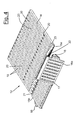
- the device for the dripping of dishes in question is indicated as a whole with 10 and includes a drip collection basin 11 in which a drainage grid 12 having a flat structure, according to the invention, is positioned.
- the collection basin 11 described in the illustrative and non-limiting embodiment has a rectangular form with rounded corners, but it can have any other geometrical shape suitable for the purpose.
- Said collection basin 11 moreover, preferably has, along two opposite sides of its perimeter, two gripping elements 13 for easier transporting of the dripping device 10.
- the drainage grid 12 comprises a first flat portion 14 consisting of a series of parallel elongated elements 19, separated by a series of connecting bridges 20. This first portion, regardless of the configuration of the dripping device 10, is horizontally housed in the basin 11.
- the drainage grid 12 also comprises a second portion 15, rotatingly constrained around a first axis defined by line 21 along which the first portion 14 and the second 15 portion border, and a third portion 16 rotatingly constrained to a second axis defined by the border line 22 between the second portion 15 and the third portion 16.
- the second portion 15 of the grid 12 also consists of a set of elongated elements 19, parallel and distanced by a series of bridges, whereas the third portion 16 of the grid 12 preferably has cells 17 having an elongated oval or rectangular form.
- the respective elongated elements 19 In correspondence with the border line 21 between the first portion 14 and the second 15 portion of the grid, the respective elongated elements 19 have a reduced thickness 23 to form a weakened line, which allows the rotation of the second portion 15 around the first axis 21.
- the two portions 14 and 15 can obviously be produced separately and can be hinged to each other by means of pins.
- Said elongated elements 19 preferably have a rounded termination 23, in correspondence with said border line 21.
- said portions have a reduced thickness 24 which forms a weakened line.
- the second portion 15 and third portion 16 are preferably each subdivided into two independent sub-portions 15a, 15b and 16a, 16b.
- the particular structure of the drainage grid 12, according to the invention, allows it to be arranged with different configurations, according to the particular use of the dripping device 10.
- the drainage grid 12 is completely housed inside the collection basin 11 and in particular the first portion 14 and the second portion 15 of the grid form the supporting surface of the dripping device 10, whereas the third portion 16 of the grid is positioned below the second portion 15, in a folded configuration.
- Figure 2 shows a first operational configuration, in which a sub-portion 15a, 15b, 16a, 16b of the second portion 15 and third portion 16 of the grid are tilted with respect to the first portion 14 of the grid, so as to form a prismatic structure with the collection basin 11, having a triangular section.
- figure 3 shows a second operational configuration in which the whole second 15 and third 16 grid portions are tilted with respect to the first portion 14, so as to form a prismatic structure with the collection basin 11, having a triangular section.
- the third portion 16 is advantageously equipped with holding flaps 18 which facilitate the lifting of the second portion 15 and third portion 16 of the grid 12 to move them from a folded resting position to an operational configuration.
- the lifted grid portions 12 act as a support for the vertical housing of the dishes, thus increasing, when necessary, the capacity of the dripping device. Furthermore, in the grid cells 17 of the third portion 16, cutlery, for example, can be inserted, to keep it lifted, thus occupying a smaller dripping surface.
- the dripping device When not in use, on the contrary, the dripping device can be put in a rest configuration, in which it has a flat structure and therefore has an encumbrance similar to the known dripping devices using grids with an exclusively horizontal development.
- a dripping device using said drainage grid therefore has the advantage of a high capacity and can also act as a supporting plane when empty.
- the rotation hinges of the grid portions for example, which, in the embodiment described, are produced by means of weakened lines of the same portions, can be obtained by suitable means, such as a rotation pin.
Landscapes
- Sink And Installation For Waste Water (AREA)
- Table Devices Or Equipment (AREA)
- Meat, Egg Or Seafood Products (AREA)
- Baking, Grill, Roasting (AREA)
Applications Claiming Priority (1)
| Application Number | Priority Date | Filing Date | Title |
|---|---|---|---|
| IT002427A ITMI20062427A1 (it) | 2006-12-19 | 2006-12-19 | Griglia di scolo per dispositivo di sgocciolamento di stoviglie e dispositivo impiegante la stessa |
Publications (1)
| Publication Number | Publication Date |
|---|---|
| EP1935324A1 true EP1935324A1 (en) | 2008-06-25 |
Family
ID=39046935
Family Applications (1)
| Application Number | Title | Priority Date | Filing Date |
|---|---|---|---|
| EP07123396A Withdrawn EP1935324A1 (en) | 2006-12-19 | 2007-12-17 | Drainage grid for a dish dripping device and dish dripping device using the same |
Country Status (3)
| Country | Link |
|---|---|
| US (1) | US20080149644A1 (it) |
| EP (1) | EP1935324A1 (it) |
| IT (1) | ITMI20062427A1 (it) |
Cited By (1)
| Publication number | Priority date | Publication date | Assignee | Title |
|---|---|---|---|---|
| IT201700066180A1 (it) * | 2017-06-14 | 2018-12-14 | Vibo S P A | Scolapiatti modulare |
Families Citing this family (29)
| Publication number | Priority date | Publication date | Assignee | Title |
|---|---|---|---|---|
| USD732256S1 (en) * | 2012-03-26 | 2015-06-16 | Anho Houseware Co., Ltd. (Jiangmen) | Dish rack |
| US8925742B1 (en) * | 2012-06-14 | 2015-01-06 | David Dennys Chitayat | Folding dishrack with articulating tines |
| US8960452B2 (en) * | 2012-12-11 | 2015-02-24 | Handi-Craft Company | Drying rack assembly |
| US8925743B1 (en) * | 2013-08-30 | 2015-01-06 | Helen Of Troy Limited | Dish drying rack |
| WO2015123247A1 (en) * | 2014-02-11 | 2015-08-20 | Lifetime Brands, Inc. | Folding dish drying rack |
| US20160113479A1 (en) * | 2014-10-22 | 2016-04-28 | Christopher Hawker | Dish rack |
| USD770715S1 (en) * | 2015-11-19 | 2016-11-01 | Polder Products, Llc | Drying mat and tray |
| US9907453B2 (en) | 2015-12-22 | 2018-03-06 | Umbra Llc | Combination dish drying mat and rack |
| US9730571B1 (en) * | 2016-02-11 | 2017-08-15 | Robinson Home Products Inc. | Foldable dish rack |
| USD801612S1 (en) * | 2016-03-03 | 2017-10-31 | Umbra Llc | Combination dish drying mat and rack |
| USD781518S1 (en) | 2016-03-03 | 2017-03-14 | Umbra Llc | Combination dish drying mat and rack |
| USD774719S1 (en) | 2016-03-25 | 2016-12-20 | Umbra Llc | Combination drying mat and rack |
| USD776386S1 (en) | 2016-03-29 | 2017-01-10 | Umbra, Llc | Combination drying mat and rack |
| USD830657S1 (en) * | 2016-04-05 | 2018-10-09 | Umbra Llc | Combination drying mat and rack |
| USD822930S1 (en) | 2017-06-15 | 2018-07-10 | Umbra Llc | Dish drying rack |
| US10827884B2 (en) * | 2017-11-17 | 2020-11-10 | DV International Inc. | Bakeware and cookware organizer |
| USD881601S1 (en) * | 2018-03-20 | 2020-04-21 | Umbra Llc | Shoe mat |
| US10314413B1 (en) * | 2018-06-25 | 2019-06-11 | Tod Smith | Method and apparatus for convention pouring and holding of candy foods |
| JP1641953S (it) * | 2018-08-17 | 2019-09-24 | ||
| US11039731B2 (en) * | 2018-12-06 | 2021-06-22 | Hongyuan Han | Nesting, dish drying rack |
| US20240406640A1 (en) * | 2020-04-17 | 2024-12-05 | Dorai Home, Inc. | Over-the-sink drying element |
| USD955076S1 (en) * | 2020-08-17 | 2022-06-14 | Zak Wood | Foldable dish drying rack with removable utensil holder |
| US11103121B1 (en) * | 2020-08-21 | 2021-08-31 | Zak Wood | Foldable dish drying rack with removable utensil holder |
| USD1008596S1 (en) | 2021-04-30 | 2023-12-19 | Umbra Llc | Expandable drying rack |
| US11712148B2 (en) * | 2021-08-13 | 2023-08-01 | Haier Us Appliance Solutions, Inc. | Collapsible rack for dishwasher appliance |
| USD995024S1 (en) * | 2022-05-16 | 2023-08-08 | Dongguan Zhichen Rubber Products Co., Ltd. | Drain pad |
| US11717135B1 (en) * | 2022-08-18 | 2023-08-08 | Zak Wood | Foldable kitchenware drying rack |
| US12329347B2 (en) * | 2023-08-25 | 2025-06-17 | Umbra Llc | Combination drying mat, rack and storage container |
| USD1104613S1 (en) * | 2024-12-17 | 2025-12-09 | Pengzhe Su | Chopping board rack |
Citations (5)
| Publication number | Priority date | Publication date | Assignee | Title |
|---|---|---|---|---|
| FR6207E (fr) * | 1905-11-06 | 1906-09-21 | Louis Vincent | Égouttoir mobile articulé |
| NL7102203A (en) * | 1971-02-19 | 1972-08-22 | Drainage rack - for household dishes produced from plastic and provided with grooves and fold lines | |
| GB2042147A (en) * | 1979-02-05 | 1980-09-17 | Leifheit International | Table-ware draining rack |
| US6170676B1 (en) * | 1999-03-09 | 2001-01-09 | Sona Patadia | Foldable dish drainer |
| US20020084233A1 (en) * | 2000-05-11 | 2002-07-04 | Rudolph Martorella | Device for drying objects |
Family Cites Families (4)
| Publication number | Priority date | Publication date | Assignee | Title |
|---|---|---|---|---|
| US1835232A (en) * | 1930-11-17 | 1931-12-08 | Thomas G Lord | Dish drainer |
| US3497127A (en) * | 1968-01-30 | 1970-02-24 | Theodor Box | Collapsible plastic case |
| US6364130B2 (en) * | 2000-01-14 | 2002-04-02 | Progressive International Corp. | Dish rack |
| US6357605B1 (en) * | 2000-05-11 | 2002-03-19 | Rudolph Martorella | Device for drying objects |
-
2006
- 2006-12-19 IT IT002427A patent/ITMI20062427A1/it unknown
-
2007
- 2007-12-17 US US12/002,383 patent/US20080149644A1/en not_active Abandoned
- 2007-12-17 EP EP07123396A patent/EP1935324A1/en not_active Withdrawn
Patent Citations (5)
| Publication number | Priority date | Publication date | Assignee | Title |
|---|---|---|---|---|
| FR6207E (fr) * | 1905-11-06 | 1906-09-21 | Louis Vincent | Égouttoir mobile articulé |
| NL7102203A (en) * | 1971-02-19 | 1972-08-22 | Drainage rack - for household dishes produced from plastic and provided with grooves and fold lines | |
| GB2042147A (en) * | 1979-02-05 | 1980-09-17 | Leifheit International | Table-ware draining rack |
| US6170676B1 (en) * | 1999-03-09 | 2001-01-09 | Sona Patadia | Foldable dish drainer |
| US20020084233A1 (en) * | 2000-05-11 | 2002-07-04 | Rudolph Martorella | Device for drying objects |
Cited By (1)
| Publication number | Priority date | Publication date | Assignee | Title |
|---|---|---|---|---|
| IT201700066180A1 (it) * | 2017-06-14 | 2018-12-14 | Vibo S P A | Scolapiatti modulare |
Also Published As
| Publication number | Publication date |
|---|---|
| ITMI20062427A1 (it) | 2008-06-20 |
| US20080149644A1 (en) | 2008-06-26 |
Similar Documents
| Publication | Publication Date | Title |
|---|---|---|
| EP1935324A1 (en) | Drainage grid for a dish dripping device and dish dripping device using the same | |
| US6546942B2 (en) | Dishwasher with auxiliary basket | |
| US6170676B1 (en) | Foldable dish drainer | |
| US7407059B2 (en) | Drying storage rack | |
| US8167147B2 (en) | Dish drainer | |
| US3960290A (en) | Utility basket for a dishwasher | |
| US8087108B2 (en) | Sink protector | |
| US5344029A (en) | Dishwasher holddown rack | |
| US6571965B1 (en) | Dishwasher rack with pivotable fences | |
| US8573410B2 (en) | Collapsible dish drying rack | |
| AU2001259694B2 (en) | Device for drying objects | |
| US8789711B2 (en) | Dishwasher with crockery basket having adjustable storage tray | |
| US6357605B1 (en) | Device for drying objects | |
| US20140166599A1 (en) | Drying rack assembly | |
| KR20070039542A (ko) | 다양한 방법으로 도기를 담기 위한 도기 바스켓 | |
| ES2382476T3 (es) | Soporte para artículos para lavar para un lavavajillas | |
| US20140091508A1 (en) | Integrated folding cutlery retaining and cutting board apparatus | |
| NL8000584A (nl) | Vaatafdruiprek. | |
| CA2538614A1 (en) | Dish draining apparatus | |
| EP1518490A1 (en) | Basket for washing drying and storing glasses | |
| CN214452726U (zh) | 一种可作为茶席的多功能折叠盒 | |
| CN209450325U (zh) | 一种堆叠锅具 | |
| TWM522655U (zh) | 折疊式收納架 | |
| CN224023524U (zh) | 搁架组件及洗碗机 | |
| CN210902027U (zh) | 一种收纳筐 |
Legal Events
| Date | Code | Title | Description |
|---|---|---|---|
| PUAI | Public reference made under article 153(3) epc to a published international application that has entered the european phase |
Free format text: ORIGINAL CODE: 0009012 |
|
| AK | Designated contracting states |
Kind code of ref document: A1 Designated state(s): AT BE BG CH CY CZ DE DK EE ES FI FR GB GR HU IE IS IT LI LT LU LV MC MT NL PL PT RO SE SI SK TR |
|
| AX | Request for extension of the european patent |
Extension state: AL BA HR MK RS |
|
| AKX | Designation fees paid | ||
| REG | Reference to a national code |
Ref country code: DE Ref legal event code: 8566 |
|
| STAA | Information on the status of an ep patent application or granted ep patent |
Free format text: STATUS: THE APPLICATION IS DEEMED TO BE WITHDRAWN |
|
| 18D | Application deemed to be withdrawn |
Effective date: 20081228 |