EP1935367B1 - Pièce à main médicale et buse échangeable destinée à celle-ci - Google Patents
Pièce à main médicale et buse échangeable destinée à celle-ci Download PDFInfo
- Publication number
- EP1935367B1 EP1935367B1 EP07021725A EP07021725A EP1935367B1 EP 1935367 B1 EP1935367 B1 EP 1935367B1 EP 07021725 A EP07021725 A EP 07021725A EP 07021725 A EP07021725 A EP 07021725A EP 1935367 B1 EP1935367 B1 EP 1935367B1
- Authority
- EP
- European Patent Office
- Prior art keywords
- nozzle
- sealing surface
- line
- spring
- sealing
- Prior art date
- Legal status (The legal status is an assumption and is not a legal conclusion. Google has not performed a legal analysis and makes no representation as to the accuracy of the status listed.)
- Active
Links
Images


Classifications
-
- A—HUMAN NECESSITIES
- A61—MEDICAL OR VETERINARY SCIENCE; HYGIENE
- A61C—DENTISTRY; APPARATUS OR METHODS FOR ORAL OR DENTAL HYGIENE
- A61C19/00—Dental auxiliary appliances
- A61C19/06—Implements for therapeutic treatment
- A61C19/063—Medicament applicators for teeth or gums, e.g. treatment with fluorides
-
- A—HUMAN NECESSITIES
- A61—MEDICAL OR VETERINARY SCIENCE; HYGIENE
- A61C—DENTISTRY; APPARATUS OR METHODS FOR ORAL OR DENTAL HYGIENE
- A61C17/00—Devices for cleaning, polishing, rinsing or drying teeth, teeth cavities or prostheses; Saliva removers; Dental appliances for receiving spittle
- A61C17/02—Rinsing or air-blowing devices, e.g. using fluid jets or comprising liquid medication
- A61C17/0202—Hand-pieces
-
- A—HUMAN NECESSITIES
- A61—MEDICAL OR VETERINARY SCIENCE; HYGIENE
- A61C—DENTISTRY; APPARATUS OR METHODS FOR ORAL OR DENTAL HYGIENE
- A61C3/00—Dental tools or instruments
- A61C3/02—Tooth drilling or cutting instruments; Instruments acting like a sandblast machine
- A61C3/025—Instruments acting like a sandblast machine, e.g. for cleaning, polishing or cutting teeth
Definitions
- the present invention relates to a medical handpiece according to the preamble of claim 1, as well as a replaceable nozzle suitable therefor according to the preamble of claim 6. More particularly, the present invention relates to a medical handpiece for dental use, which has a replaceable nozzle which is suitable for supplying an air Powder mixture and a fluid is suitable.
- Such handpieces for example, for a dental Abrasivstrahlêt are from the EP 1 346 700 A1 , or the DE 103 31 583 known. These handpieces usually have two or three handle-side leads, which are connected to two nozzle lines, which open at a nozzle tip into the open and there let escape the medically effective fluids or mixtures.
- a nozzle piece in which the outlet of a first nozzle line for an air-powder mixture of a concentrically arranged outer outlet a second nozzle line for the outlet of a fluid is surrounded.
- the two outlets are connected via connection bores to two separate connection lines of a separately designed and fixed to the head end of a handpiece grip part.
- a supragingivale powder jet cleaning can be supported with a simultaneous fluid irradiation of the treated tooth surface to allow their gentle processing in a dental cleaning to be performed.
- the US 2006/0105292 A1 discloses a replaceable nozzle part of a syringe for supplying a medically active medium, wherein the nozzle is fastened by means of a screw cap on the head part of a syringe, so that the nozzle can be replaced for hygienic reasons after each treatment.
- the EP 1 243 227 A2 discloses a medical handpiece according to the preamble of claim 1, which is equipped with a nozzle having two nozzle lines for the supply of a powder-air mixture and water, wherein the nozzle is interchangeably arranged on the handle sleeve of the medical handpiece.
- a tongue and groove joint which is designed such that two connecting lines, which are arranged between the grip sleeve and the nozzle, both in the grip sleeve and in two connection lines of the nozzle open, as stepped holes are formed, wherein the located at the respective proximal ends of the larger diameter of the stepped holes of the connecting lines for insertion of the connecting lines are adapted, and wherein the front end of the nozzle outlet pipes are mounted to appropriate To obtain outlet cross sections.
- a major disadvantage of the known interchangeable nozzles is that they must be cumbersome sterilized before they can be used for the next treatment.
- the structure and the nature of the connection between the handle side supply line and nozzle line is cumbersome because z.
- additional connection lines are provided, which come to rest between the grip sleeve and the nozzle and are often clogged or cumbersome to clean, which is why these often need to be replaced.
- the EP 0 299 229 discloses an attachment for a dental handpiece, by means of which it can be prevented that the tooth-treating medium unintentionally reaches the oral cavity remaining in the circulation by the collar is collar-shaped and is placed with its front end on the tooth.
- the US 4,519,385 discloses a handpiece by means of which a fluid can be supplied to a surgical site, the handpiece at the same time offers the possibility to suck the fluid from the surgical site again.
- the present invention has for its object to improve the medical handpiece of the prior art in that a cumbersome disinfection is accelerated or eliminated, the structure and manufacture of the medical handpiece and the nozzle is easier and cheaper and that the idle time between two treatments one Patients are getting shorter so more patients can be treated faster with the medical handpiece.
- the medical handpiece of the present invention has a nozzle with two nozzle supply lines which serve to supply the powder-air mixture and the fluid.
- On the handpiece is located, and the front part of the handpiece is a head part with a head-side connecting part for interchangeable connection of the handpiece with the nozzle, wherein the handpiece has two leads, with the aid of the powder-air mixture and the fluid are supplied.
- the two supply lines are connected to the nozzle feed lines by a sealing press fit, a nozzle-side sealing surface and a handle-side head-side sealing surface.
- the advantage of the present invention is that no connection lines or other connection parts are necessary to connect the nozzle supply lines of the nozzle with the supply lines of the handle part.
- the main advantage of such an arrangement is that the nozzle can be made very small and inexpensive, so that it is used as a disposable article and no longer needs to be disinfected.
- the sealing press fit must be achieved by the simplest possible means. This has the advantage that the relatively small and thin channels inside the nozzle no longer need to be cleaned or disinfected, because the nozzle itself is disposed of after each use and a new nozzle is used with each application.
- the grip-side sealing surface is arranged at the end of a handle-side T-spring or T-groove of the head part, in which a nozzle-side T-slot or T-spring can be inserted, which carries the nozzle-side sealing surface.
- the insertion axis for inserting the T-slot in the T-spring is approximately perpendicular to the longitudinal axis of the handpiece, wherein insertion angle of advantageously 45 ° - 135 °, particularly preferably 80 ° - 100 ° come into question.
- the nozzle-side sealing surface has two line seals which seal the two conduit openings into which the nozzle supply lines open. These line seals may be arranged in a circle around the line openings of the nozzle supply lines and consist of the same material as the nozzle itself. According to another embodiment, the handle-side sealing surface at the conduit openings of the leads on line seals, which then allow a sealing interference fit of the nozzle-side sealing surface and the handle-side sealing surface such that the opposite conduit openings of supply and Düsenzuschreibschreib be sealed to the outside.
- the nozzle can also be attached by a bayonet, twist or a screw on the connecting part, so that there is a sealing interference fit of the nozzle-side sealing surface and the handle-side sealing surface, wherein in the case of Line seals these sealing surfaces are represented by the surfaces of the line seals themselves.
- the planes of the sealing surfaces are substantially perpendicular to the longitudinal axis of the handpiece.
- the present invention further relates to a nozzle for a medical handpiece according to claim 6.
- a first nozzle supply opens with a second nozzle supply at the nozzle tip according to the invention optionally such that the powder-air mixture and the fluid at the same time, possibly separated, emerge at the nozzle tip.
- the nozzle consists of an elastically deformable plastic material, in particular of an elastomer, so that when inserting the nozzle in the head-side connecting part, a deformation of the plastic material is possible, thus achieving a sealing interference fit.
- the line seals are formed from the same material as the nozzle, possibly in one piece with this, for example, by an injection molding process can be designed as a disposable item.
- Fig. 1 shows the schematic cross section through the front part of a medical handpiece 1, which has at its front part a head part 4, which carries a head-side connecting part 6 for connecting the handpiece 1 with a nozzle 5.
- a head part 4 which carries a head-side connecting part 6 for connecting the handpiece 1 with a nozzle 5.
- the longitudinal axis L of the handpiece 1 is shown, which is approximately perpendicular to the connecting or Einstockedachse 1, which lies in a plane parallel to the planes in which the nozzle-side sealing surface and the handle-side sealing surface (see. 3 and 4 ) lie.
- the handpiece 1 has a first supply line 9 for supplying, for example, an air-powder mixture and a second supply line 10 for supplying, for example, water.
- Fig. 1 is a right sliding groove 7a recognizable, which protrudes below the head-side connecting part 6.
- the nozzle 5 has a nozzle tip 8, to which a first nozzle supply line 11 and a second nozzle supply line 12 lead, the first nozzle supply line 11 sealingly connected to the first supply line 9, and the second nozzle supply line 12 sealingly connected to the second supply line 10.
- Fig. 2 schematically shows the medical handpiece 1 with front head part 4, nozzle 5 and a connector 3 of the handpiece 1, to which a hose 2 can be connected.
- the air-powder mixture and the water is supplied; if there is a powder container in or on the handpiece 1, only compressed air and water can be supplied via the hose 2.
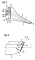
- Fig. 3 schematically shows the rear transverse view of the nozzle 5, wherein the first nozzle supply line 11 and the second nozzle supply line 12 are schematically indicated within the nozzle 5. Both nozzle feed lines 11, 12 open at the nozzle tip 8.
- the first nozzle feed line 11 is fed via a first line opening 13a, while the second nozzle feed line 12 is fed via a second line opening 13b.
- To the pipe openings 13a, 13b around line seals 14a, 14b are indicated.
- These line seals 14a, 14b can take any shape as long as it is ensured that both an outward seal and a seal between the line openings 13a, 13b is ensured.
- the line seals 14a, 14b could also be arranged on the edge of the sealing surface 16, whereby a transverse sealing groove must then be provided between the two line openings 13a, 13b.
- the line seals 14a, 14b are made in one piece from the same material as the nozzle 5 in order to keep the costs of the nozzle 5 as low as possible.
- the nozzle 5 has a nozzle-side T-groove 21 which is formed by having a right sliding groove 7a and a left sliding groove 7b spaced from the sealing surface 16, notched laterally into the surface of the nozzle 5.
- the slide grooves 7a, 7b do not extend completely over the entire surface of the nozzle 5, but terminate shortly below the upper extent of the nozzle 5, so that a Nutabsatz 15 is formed. This Nutabsatz 15 prevents when inserted into the head-side connecting part 6 (see. Fig. 4 ) a slippage of the nozzle. 5
- Fig. 4 schematically shows the transverse view of the head-side connecting part 6.
- connecting part 6, headboard 4 and handpiece 1 may be integrally formed.
- the connecting part 6 has, in particular, a grip-side T-spring 18, which is formed by a T-shaped cutout on the front part of the connecting part 6 approximately at right angles to the longitudinal axis L of the handpiece 1.
- the T-shaped cutout results in a right spring clip 17a and a left spring clip 17b, which engage in the corresponding slide grooves 7a, 7b of the nozzle-side T-slot 21.
- the nozzle-side sealing surface 16 may be formed trapezoidal in plan view (see. Fig. 3 ), so that the lateral longitudinal edges of the nozzle-side sealing surfaces 16 cooperate with the lateral longitudinal edges of the handle side T-spring 18 such that when inserting the nozzle 5 in the head-side connecting part 6, the interference fit is effected.
- the lower transverse side of the trapezoidal sealing surface 16 is smaller than the upper width of the T-shaped cutout on the connecting part 6, while the upper transverse side of the trapezoidal sealing surface 16 in the region of the Nutabsatzes 15 is greater than the upper width of the T-shaped cutout the connecting part 6, so that when inserting the nozzle 5, a clamping is effected.
- both the nozzle-side sealing surface 16 and the slide grooves 7a, 7b accordingly Fig. 5
- the grip side T-spring 18 is adjusted accordingly, ie in particular cuboid shaped.
- the T-shaped cut-out in the connecting part 6 correspondingly trapezoidal, so that then a rectangular shaped sealing surface 16 runs in the T-spring 18 at the trapezoidal shaped cutout there and clamps there.
- the clamping of the two components is preferably achieved in that on the one hand the nozzle-side sealing surface 16 is pressed onto the handle-side sealing surface 19 and on the other hand, the surfaces of the right and left sliding 7a, 7b on the right and left Spring clips 17a, 17b support accordingly and the side of the sliding grooves 7a, 7b adjacent surfaces of the nozzle-side T-groove 21 at the spring clips 17a, 17b adjacent surfaces of the handle side T-spring 18 are respectively supported.
- these corresponding surfaces are arranged at an angle of about 4 ° relative to the nozzle-side and handle-side sealing surfaces 16 and 19, so that with increasing insertion depth, the two sealing surfaces 16th , 19 are more and more pressed apart.
- this embodiment of the nozzle 5 can be produced as a disposable item, so that a cumbersome disinfection is eliminated.
- the replacement takes place without any aids by simply inserting the nozzle 5 in the head-side Connecting part 6. Due to the conical or trapezoidal configuration of the nozzle-side T-slot and / or the handle T-spring a reliable interference fit can be achieved to a reliable sealing of the connection point between the leads 9, 10 and the nozzle supply lines 11, 12 achieve.
Landscapes
- Health & Medical Sciences (AREA)
- Dentistry (AREA)
- Epidemiology (AREA)
- Life Sciences & Earth Sciences (AREA)
- Animal Behavior & Ethology (AREA)
- General Health & Medical Sciences (AREA)
- Public Health (AREA)
- Veterinary Medicine (AREA)
- Oral & Maxillofacial Surgery (AREA)
- Dental Tools And Instruments Or Auxiliary Dental Instruments (AREA)
- Infusion, Injection, And Reservoir Apparatuses (AREA)
Claims (10)
- Pièce à main médicale (1) comprenant une buse (5) capable d'être reliée à celle-ci, qui comprend une première conduite d'amenée de buse (11) pour un mélange poudre/air et une seconde conduite d'amenée de buse pour un fluide, et une partie de tête (4) qui comprend une première conduite d'amenée (9) et une seconde conduite d'amenée (10) pour l'amenée du mélange air/poudre ainsi que du fluide, dans laquelle la partie de tête (4) comprend une partie de liaison (6), côté tête, pour la liaison interchangeable de la pièce à main (1) avec la buse (5),
caractérisée par une surface d'étanchéité (16) côté buse et par une surface d'étanchéité (19) côté poignée, telles que la surface d'étanchéité côté buse comprend une première ouverture de conduite (13a, 13b) pour la première conduite de buse (11) et une seconde ouverture de conduite (13b) pour une seconde conduite de buse (12), qui sont entourées respectivement par un premier joint de conduite (14a) et par un second joint de conduite (14b) qui, lors de la liaison de la buse avec la partie de tête (4), établissent un ajustement pressé étanche par rapport aux ouvertures de la première et de la seconde conduite d'amenée (9, 10), via un engagement d'une gorge (21) en forme de T avec un ressort (18) en forme de T. - Pièce à main médicale selon la revendication 1,
caractérisée en ce que la surface d'étanchéité (19) côté poignée est agencée à l'extrémité d'un ressort (18) en forme de T et situé côté poignée de la partie de tête (4), susceptible d'être introduit dans une gorge en forme de T (21) côté buse, qui porte la surface d'étanchéité (16) côté buse. - Pièce à main médicale selon la revendication 2,
caractérisée en ce que la gorge en forme de T (21) côté buse forme une gorge de coulissement de droite (7a) et une gorge de coulissement de gauche (7b) dans lesquelles s'engagent une pince-ressort (17a) à droite et une pince-ressort (17b) à gauche du ressort en forme de T (18) côté poignée, de sorte que l'on assure un ajustement pressé et étanche entre la surface d'étanchéité (16) côté buse et la surface d'étanchéité (19) côté poignée. - Pièce à main médicale selon la revendication 3,
caractérisée en ce que la surface d'étanchéité (16) côté buse est conformée en vue de dessus en forme de trapèze, de sorte que les arêtes longitudinales latérales des surfaces d'étanchéité (16) côté buse coopèrent avec les arêtes longitudinales latérales du ressort en forme de T (18) côté poignée de telle manière que lors de l'introduction de la buse (5) dans la pièce de liaison (6) côté tête, on réalise l'ajustement pressé. - Pièce à main médicale selon l'une des revendications 2 à 4,
caractérisée en ce qu'une largeur inférieure (d1) de la gorge en forme de T (21) côté buse est supérieure à une largeur supérieure (d2) de ladite gorge, de sorte que l'épaisseur inférieure de la surface d'étanchéité (16) côté buse est inférieure à l'épaisseur supérieure de la surface d'étanchéité (16) côté buse, et que l'épaisseur inférieure de la surface d'étanchéité (16) côté buse est inférieure à la largeur (a) du ressort en forme de T côté poignée (18), mais que l'épaisseur supérieure de la surface d'étanchéité (16) côté buse est supérieure à la largeur (a) du ressort en forme de T. - Buse (5) pour une pièce à main médicale (1) selon l'une des revendications précédentes, comprenant une première conduite d'amenée de buse (11) pour un mélange poudre/air et une seconde conduite d'amenée de buse (12) pour un fluide, dans laquelle la buse (5) comporte une surface d'étanchéité (16) côté buse avec une première ouverture de conduite (13a) pour la première conduite d'amenée de buse (11) et une seconde ouverture de conduite (13b) pour la seconde conduite d'amenée de buse (12), lesquelles sont respectivement entourées par un premier joint de conduite (14a) et par un second joint de conduite (14b), dans laquelle la surface d'étanchéité (16) côté buse est susceptible d'être reliée avec une surface d'étanchéité (19) côté poignée d'une pièce de tête (4) de manière étanche, via un engagement d'une gorge en forme de T (21) avec un ressort en forme de T (18), de telle manière que la première et la seconde ouverture de conduite (13a, 13b) sont susceptibles d'être reliées de manière étanche via un ajustement pressé au moyen des joints de conduites (14a, 14b) avec les ouvertures d'une première et d'une seconde conduite d'amenée (9, 10).
- Buse (5) selon la revendication 6,
caractérisée en ce que la première conduite d'amenée de buse (11) et la seconde conduite d'amenée de buse (12) débouchent au niveau d'une pointe de buse (8) de telle manière que deux milieux médicalement actifs peuvent sortir simultanément au niveau de la pointe de buse (8). - Buse selon la revendication 6 ou 7,
caractérisée en ce que la buse et en une matière plastique élastiquement déformable, en particulier un élastomère. - Buse selon l'une des revendications 6 à 8,
caractérisée en ce que la buse est d'une seule pièce. - Buse selon l'une des revendications 6 à 9,
caractérisée en ce que les joints de conduite (14a, 14b) sont du même matériau que la buse (5).
Applications Claiming Priority (1)
| Application Number | Priority Date | Filing Date | Title |
|---|---|---|---|
| DE102006060076A DE102006060076B3 (de) | 2006-12-19 | 2006-12-19 | Medizinisches Handstück und auswechselbare Düse für ein solches |
Publications (2)
| Publication Number | Publication Date |
|---|---|
| EP1935367A1 EP1935367A1 (fr) | 2008-06-25 |
| EP1935367B1 true EP1935367B1 (fr) | 2010-05-12 |
Family
ID=39105471
Family Applications (1)
| Application Number | Title | Priority Date | Filing Date |
|---|---|---|---|
| EP07021725A Active EP1935367B1 (fr) | 2006-12-19 | 2007-11-08 | Pièce à main médicale et buse échangeable destinée à celle-ci |
Country Status (8)
| Country | Link |
|---|---|
| US (1) | US7762812B2 (fr) |
| EP (1) | EP1935367B1 (fr) |
| JP (1) | JP5171233B2 (fr) |
| CN (1) | CN101204599B (fr) |
| AT (1) | ATE467396T1 (fr) |
| CA (1) | CA2615170C (fr) |
| DE (3) | DE102006060076B3 (fr) |
| ES (1) | ES2341492T3 (fr) |
Families Citing this family (18)
| Publication number | Priority date | Publication date | Assignee | Title |
|---|---|---|---|---|
| WO2011077291A1 (fr) * | 2009-12-23 | 2011-06-30 | Koninklijke Philips Electronics N.V. | Embout d'ensemble de guidage pour appareil de nettoyage des dents à pulvérisation de gouttelettes de liquide |
| DE102010051227A1 (de) | 2010-11-12 | 2012-05-16 | Dental Care Innovation Gmbh | Düse zur Abstrahlung von flüssigen Reinigungsmitteln mit darin dispergierten abrasiven Partikeln |
| WO2014099490A2 (fr) | 2012-12-17 | 2014-06-26 | 3M Innovative Properties Company | Dispositif d'administration de produit dentaire avec mécanisme de verrouillage |
| EP2742897A1 (fr) | 2012-12-17 | 2014-06-18 | 3M Innovative Properties Company | Buse, pièce à main et dispositif à jet de poudre pour appliquer un matériau dentaire |
| EP2742898A1 (fr) | 2012-12-17 | 2014-06-18 | 3M Innovative Properties Company | Dispositif à jet de poudre pour diffusion de matériau dentaire |
| JP6449761B2 (ja) | 2013-03-07 | 2019-01-09 | 株式会社ナカニシ | 歯科用ハンドピースのノズル |
| WO2014136846A1 (fr) | 2013-03-07 | 2014-09-12 | 株式会社ナカニシ | Pièce à main dentaire ayant une structure de liaison de buse |
| DE102016124212B4 (de) * | 2016-12-13 | 2022-05-12 | Ferton Holding S.A. | Mischkammer und Handstück |
| USD825741S1 (en) | 2016-12-15 | 2018-08-14 | Water Pik, Inc. | Oral irrigator handle |
| KR102625450B1 (ko) | 2017-03-16 | 2024-01-16 | 워어터 피이크, 인코포레이티드 | 구강 작용제와 함께 사용하기 위한 구강 세척기 핸들 |
| EP3427691B1 (fr) * | 2017-07-14 | 2019-12-04 | W & H Dentalwerk Bürmoos GmbH | Unité de traitement de prophylaxie dentaire |
| CN109419560B (zh) * | 2017-08-19 | 2024-07-19 | 周星 | 用于可视牙齿冲洗器的喷头及可视牙齿冲洗器 |
| CN109124796B (zh) * | 2018-09-28 | 2020-12-29 | 先临三维科技股份有限公司 | 注塑装置及其牙模成型方法 |
| DE102018126926A1 (de) | 2018-10-29 | 2020-04-30 | Dürr Dental SE | Auswechselbare Düsenspitze für ein dentales Pulverstrahlgerät |
| DK3705076T3 (da) * | 2019-03-07 | 2023-04-24 | Ferton Holding Sa | Dyseelement og tandbehandlingsindretning med et sådant dyseelement |
| US11052205B2 (en) | 2019-06-11 | 2021-07-06 | Neosinus Health Inc | Devices and methods for delivering fluid to a nasal cavity |
| CN211325726U (zh) * | 2019-11-13 | 2020-08-25 | 桂林市啄木鸟医疗器械有限公司 | 一种可旋转牙科喷砂机龈下喷头喷嘴 |
| WO2024028344A1 (fr) * | 2022-08-03 | 2024-02-08 | GalvoSurge Dental AG | Buse d'application pour faire sortir un principe actif dentaire dans la cavité buccale d'un patient et applicateur de principe actif doté d'une telle buse d'application |
Family Cites Families (13)
| Publication number | Priority date | Publication date | Assignee | Title |
|---|---|---|---|---|
| US4519385A (en) | 1982-12-01 | 1985-05-28 | Snyder Laboratories, Inc. | Lavage handpiece |
| US4850868A (en) | 1987-07-13 | 1989-07-25 | Dentsply Research & Development Corp. | Spray shield |
| GR920100104A (el) * | 1992-03-13 | 1993-11-30 | Christodoulos I Stefanadis | Προσωρινή διαυλική ενδοπρόσ?εση υποστήριξης αγγειακού τοιχώματος. |
| US5242300A (en) * | 1992-12-23 | 1993-09-07 | Esrock Bernard S | Nozzle for dental tool |
| DE19714276C2 (de) * | 1997-04-07 | 2001-04-19 | Ferton Holding Sa | Zahnärztliches Handstück |
| JP4159202B2 (ja) * | 1998-12-21 | 2008-10-01 | 日本特殊陶業株式会社 | リン酸カルシウム系セメント用混練器具及びリン酸カルシウム系セメント混練物の調製方法 |
| DE10114324B4 (de) * | 2001-03-23 | 2005-03-10 | Ferton Holding Sa | Düsenstück für ein dantales Abrasivstrahlgerät |
| DE10212925B4 (de) | 2002-03-22 | 2004-07-08 | Ferton Holding S.A. | Handstück für ein dentales Abrasivstrahlgerät |
| US6783037B1 (en) * | 2003-04-10 | 2004-08-31 | John E. Bonham | Locking aerosol spray tube |
| DE10331583B3 (de) * | 2003-07-11 | 2004-07-15 | Ferton Holding S.A. | Düsenstück für ein dentales Pulverstrahlgerät |
| US7530808B2 (en) * | 2004-03-10 | 2009-05-12 | Cao Group, Inc | Binary dental bleaching using switch-closable double barrel syringe |
| CN2715857Y (zh) * | 2004-07-20 | 2005-08-10 | 刘军伍 | 点杀式气雾剂喷盖 |
| US7179085B2 (en) | 2004-11-16 | 2007-02-20 | Denteque | Apparatus for dispensing dental solutions |
-
2006
- 2006-12-19 DE DE102006060076A patent/DE102006060076B3/de active Active
-
2007
- 2007-11-08 AT AT07021725T patent/ATE467396T1/de active
- 2007-11-08 DE DE502007003719T patent/DE502007003719D1/de active Active
- 2007-11-08 EP EP07021725A patent/EP1935367B1/fr active Active
- 2007-11-08 ES ES07021725T patent/ES2341492T3/es active Active
- 2007-11-08 DE DE202007019027U patent/DE202007019027U1/de not_active Expired - Lifetime
- 2007-12-12 JP JP2007320691A patent/JP5171233B2/ja active Active
- 2007-12-14 US US11/956,596 patent/US7762812B2/en active Active
- 2007-12-17 CA CA2615170A patent/CA2615170C/fr active Active
- 2007-12-17 CN CN200710199351XA patent/CN101204599B/zh active Active
Also Published As
| Publication number | Publication date |
|---|---|
| CN101204599B (zh) | 2011-11-02 |
| DE202007019027U1 (de) | 2010-04-01 |
| ES2341492T3 (es) | 2010-06-21 |
| CA2615170C (fr) | 2016-11-15 |
| JP5171233B2 (ja) | 2013-03-27 |
| DE502007003719D1 (de) | 2010-06-24 |
| CN101204599A (zh) | 2008-06-25 |
| ATE467396T1 (de) | 2010-05-15 |
| JP2008149138A (ja) | 2008-07-03 |
| DE102006060076B3 (de) | 2008-03-27 |
| EP1935367A1 (fr) | 2008-06-25 |
| US7762812B2 (en) | 2010-07-27 |
| CA2615170A1 (fr) | 2008-06-19 |
| US20080145814A1 (en) | 2008-06-19 |
Similar Documents
| Publication | Publication Date | Title |
|---|---|---|
| EP1935367B1 (fr) | Pièce à main médicale et buse échangeable destinée à celle-ci | |
| EP1250106B1 (fr) | Canule de rin age pour rincer le canal radiculaire d'une dent | |
| DE69317965T2 (de) | Medizinische Kupplungseinrichtungen | |
| EP2397102A1 (fr) | Glissière de foret | |
| EP0574701B1 (fr) | Outil de traivail pour les os | |
| EP1159928B1 (fr) | Pièce à main médicale ayant un manche en forme de tige | |
| DE69006519T2 (de) | Reinigungs- und Desinfektionsvorrichtung für medizinische und chirurgische Geräte. | |
| DE102012100119B3 (de) | Spiegelsauger | |
| DE202004014104U1 (de) | Chirurgische Einrichtung zur Entnahme von Gewebezellen aus einer biologischen Struktur | |
| EP3210566A1 (fr) | Appareil de nettoyage des dents | |
| DE102005044841A1 (de) | Vorrichtung zur Entfernung von überschüssigem Abdruckmaterial während der Abdrucknahme eines Kiefers | |
| EP1514575B1 (fr) | Dispositif pour nettoyer des connecteurs de type Luer-Lock | |
| WO2020020824A1 (fr) | Pièce buccale de désinfection | |
| EP2124812B1 (fr) | Pièce à main médicale, en particulier médico-dentaire, comportant deux ouvertures de sortie distinctes pour des substances | |
| EP2995274B1 (fr) | Instrument dentaire à main et son boîtier de tête | |
| DE2829271C2 (de) | Vorrichtung zur Beaufschlagung einer Wundfläche mit einer sterilen Kühl- und Spülflüssigkeit | |
| DE3023816A1 (de) | Vorrichtung zur pflege der mundhoehle und der zaehne sowie zur massage des zahnfleisches | |
| EP0031126A1 (fr) | Installation de filtrage pour la stérilisation bactérielle des fluides de refroidissement dans les instruments de chirurgie dentaire | |
| DE3216017C2 (de) | Vorrichtung zum Versorgen eines Osteotomiegebietes mit steriler Kühlflüssigkeit | |
| CH657520A5 (en) | Dental instrument | |
| DE10235136B4 (de) | Interdentale Vorrichtung zur Reinigung von Zahnzwischenräumen | |
| DE202013100343U1 (de) | Vorrichtung für eine Zahnbürste, insbesondere eine mechanische oder elektromechanische Zahnbürste | |
| DE102015000002B4 (de) | Halter für medizinische Geräte in einem Reinigungsapparat | |
| DE10114656A1 (de) | Medizinisches Handstück mit einem stabförmigen Griffteil | |
| EP3917441A1 (fr) | Dispositif de maintien pour pièces à main chirurgicale |
Legal Events
| Date | Code | Title | Description |
|---|---|---|---|
| PUAI | Public reference made under article 153(3) epc to a published international application that has entered the european phase |
Free format text: ORIGINAL CODE: 0009012 |
|
| AK | Designated contracting states |
Kind code of ref document: A1 Designated state(s): AT BE BG CH CY CZ DE DK EE ES FI FR GB GR HU IE IS IT LI LT LU LV MC MT NL PL PT RO SE SI SK TR |
|
| AX | Request for extension of the european patent |
Extension state: AL BA HR MK RS |
|
| 17P | Request for examination filed |
Effective date: 20080715 |
|
| 17Q | First examination report despatched |
Effective date: 20080818 |
|
| AKX | Designation fees paid |
Designated state(s): AT BE BG CH CY CZ DE DK EE ES FI FR GB GR HU IE IS IT LI LT LU LV MC MT NL PL PT RO SE SI SK TR |
|
| GRAP | Despatch of communication of intention to grant a patent |
Free format text: ORIGINAL CODE: EPIDOSNIGR1 |
|
| GRAS | Grant fee paid |
Free format text: ORIGINAL CODE: EPIDOSNIGR3 |
|
| REG | Reference to a national code |
Ref country code: DE Ref legal event code: R138 Ref document number: 202007019027 Country of ref document: DE Free format text: GERMAN DOCUMENT NUMBER IS 502007003719 |
|
| GRAA | (expected) grant |
Free format text: ORIGINAL CODE: 0009210 |
|
| AK | Designated contracting states |
Kind code of ref document: B1 Designated state(s): AT BE BG CH CY CZ DE DK EE ES FI FR GB GR HU IE IS IT LI LT LU LV MC MT NL PL PT RO SE SI SK TR |
|
| REG | Reference to a national code |
Ref country code: GB Ref legal event code: FG4D Free format text: NOT ENGLISH |
|
| REG | Reference to a national code |
Ref country code: CH Ref legal event code: NV Representative=s name: LUCHS & PARTNER PATENTANWAELTE Ref country code: CH Ref legal event code: EP |
|
| REG | Reference to a national code |
Ref country code: NL Ref legal event code: T3 |
|
| REG | Reference to a national code |
Ref country code: ES Ref legal event code: FG2A Ref document number: 2341492 Country of ref document: ES Kind code of ref document: T3 |
|
| REG | Reference to a national code |
Ref country code: IE Ref legal event code: FG4D Free format text: LANGUAGE OF EP DOCUMENT: GERMAN |
|
| REF | Corresponds to: |
Ref document number: 502007003719 Country of ref document: DE Date of ref document: 20100624 Kind code of ref document: P |
|
| REG | Reference to a national code |
Ref country code: DE Ref legal event code: R096 Ref document number: 502007003719 Country of ref document: DE Effective date: 20100624 |
|
| REG | Reference to a national code |
Ref country code: SE Ref legal event code: TRGR |
|
| LTIE | Lt: invalidation of european patent or patent extension |
Effective date: 20100512 |
|
| PG25 | Lapsed in a contracting state [announced via postgrant information from national office to epo] |
Ref country code: LT Free format text: LAPSE BECAUSE OF FAILURE TO SUBMIT A TRANSLATION OF THE DESCRIPTION OR TO PAY THE FEE WITHIN THE PRESCRIBED TIME-LIMIT Effective date: 20100512 |
|
| PG25 | Lapsed in a contracting state [announced via postgrant information from national office to epo] |
Ref country code: LV Free format text: LAPSE BECAUSE OF FAILURE TO SUBMIT A TRANSLATION OF THE DESCRIPTION OR TO PAY THE FEE WITHIN THE PRESCRIBED TIME-LIMIT Effective date: 20100512 Ref country code: IS Free format text: LAPSE BECAUSE OF FAILURE TO SUBMIT A TRANSLATION OF THE DESCRIPTION OR TO PAY THE FEE WITHIN THE PRESCRIBED TIME-LIMIT Effective date: 20100912 Ref country code: FI Free format text: LAPSE BECAUSE OF FAILURE TO SUBMIT A TRANSLATION OF THE DESCRIPTION OR TO PAY THE FEE WITHIN THE PRESCRIBED TIME-LIMIT Effective date: 20100512 Ref country code: SI Free format text: LAPSE BECAUSE OF FAILURE TO SUBMIT A TRANSLATION OF THE DESCRIPTION OR TO PAY THE FEE WITHIN THE PRESCRIBED TIME-LIMIT Effective date: 20100512 |
|
| REG | Reference to a national code |
Ref country code: IE Ref legal event code: FD4D |
|
| PG25 | Lapsed in a contracting state [announced via postgrant information from national office to epo] |
Ref country code: PL Free format text: LAPSE BECAUSE OF FAILURE TO SUBMIT A TRANSLATION OF THE DESCRIPTION OR TO PAY THE FEE WITHIN THE PRESCRIBED TIME-LIMIT Effective date: 20100512 Ref country code: CY Free format text: LAPSE BECAUSE OF FAILURE TO SUBMIT A TRANSLATION OF THE DESCRIPTION OR TO PAY THE FEE WITHIN THE PRESCRIBED TIME-LIMIT Effective date: 20100526 |
|
| PG25 | Lapsed in a contracting state [announced via postgrant information from national office to epo] |
Ref country code: EE Free format text: LAPSE BECAUSE OF FAILURE TO SUBMIT A TRANSLATION OF THE DESCRIPTION OR TO PAY THE FEE WITHIN THE PRESCRIBED TIME-LIMIT Effective date: 20100512 Ref country code: PT Free format text: LAPSE BECAUSE OF FAILURE TO SUBMIT A TRANSLATION OF THE DESCRIPTION OR TO PAY THE FEE WITHIN THE PRESCRIBED TIME-LIMIT Effective date: 20100913 Ref country code: IE Free format text: LAPSE BECAUSE OF FAILURE TO SUBMIT A TRANSLATION OF THE DESCRIPTION OR TO PAY THE FEE WITHIN THE PRESCRIBED TIME-LIMIT Effective date: 20100512 Ref country code: GR Free format text: LAPSE BECAUSE OF FAILURE TO SUBMIT A TRANSLATION OF THE DESCRIPTION OR TO PAY THE FEE WITHIN THE PRESCRIBED TIME-LIMIT Effective date: 20100813 Ref country code: DK Free format text: LAPSE BECAUSE OF FAILURE TO SUBMIT A TRANSLATION OF THE DESCRIPTION OR TO PAY THE FEE WITHIN THE PRESCRIBED TIME-LIMIT Effective date: 20100512 |
|
| PG25 | Lapsed in a contracting state [announced via postgrant information from national office to epo] |
Ref country code: SK Free format text: LAPSE BECAUSE OF FAILURE TO SUBMIT A TRANSLATION OF THE DESCRIPTION OR TO PAY THE FEE WITHIN THE PRESCRIBED TIME-LIMIT Effective date: 20100512 Ref country code: RO Free format text: LAPSE BECAUSE OF FAILURE TO SUBMIT A TRANSLATION OF THE DESCRIPTION OR TO PAY THE FEE WITHIN THE PRESCRIBED TIME-LIMIT Effective date: 20100512 Ref country code: CZ Free format text: LAPSE BECAUSE OF FAILURE TO SUBMIT A TRANSLATION OF THE DESCRIPTION OR TO PAY THE FEE WITHIN THE PRESCRIBED TIME-LIMIT Effective date: 20100512 |
|
| PLBE | No opposition filed within time limit |
Free format text: ORIGINAL CODE: 0009261 |
|
| STAA | Information on the status of an ep patent application or granted ep patent |
Free format text: STATUS: NO OPPOSITION FILED WITHIN TIME LIMIT |
|
| 26N | No opposition filed |
Effective date: 20110215 |
|
| BERE | Be: lapsed |
Owner name: FERTON HOLDING SA Effective date: 20101130 |
|
| REG | Reference to a national code |
Ref country code: DE Ref legal event code: R097 Ref document number: 502007003719 Country of ref document: DE Effective date: 20110214 Ref country code: DE Ref legal event code: R097 Ref document number: 502007003719 Country of ref document: DE Effective date: 20110215 |
|
| PG25 | Lapsed in a contracting state [announced via postgrant information from national office to epo] |
Ref country code: MC Free format text: LAPSE BECAUSE OF NON-PAYMENT OF DUE FEES Effective date: 20101130 |
|
| PG25 | Lapsed in a contracting state [announced via postgrant information from national office to epo] |
Ref country code: BE Free format text: LAPSE BECAUSE OF NON-PAYMENT OF DUE FEES Effective date: 20101130 |
|
| PG25 | Lapsed in a contracting state [announced via postgrant information from national office to epo] |
Ref country code: IT Free format text: LAPSE BECAUSE OF NON-PAYMENT OF DUE FEES Effective date: 20101108 Ref country code: MT Free format text: LAPSE BECAUSE OF FAILURE TO SUBMIT A TRANSLATION OF THE DESCRIPTION OR TO PAY THE FEE WITHIN THE PRESCRIBED TIME-LIMIT Effective date: 20100512 |
|
| PG25 | Lapsed in a contracting state [announced via postgrant information from national office to epo] |
Ref country code: LU Free format text: LAPSE BECAUSE OF NON-PAYMENT OF DUE FEES Effective date: 20101108 Ref country code: BG Free format text: LAPSE BECAUSE OF FAILURE TO SUBMIT A TRANSLATION OF THE DESCRIPTION OR TO PAY THE FEE WITHIN THE PRESCRIBED TIME-LIMIT Effective date: 20100512 Ref country code: HU Free format text: LAPSE BECAUSE OF FAILURE TO SUBMIT A TRANSLATION OF THE DESCRIPTION OR TO PAY THE FEE WITHIN THE PRESCRIBED TIME-LIMIT Effective date: 20101113 |
|
| REG | Reference to a national code |
Ref country code: NL Ref legal event code: T3 |
|
| PG25 | Lapsed in a contracting state [announced via postgrant information from national office to epo] |
Ref country code: TR Free format text: LAPSE BECAUSE OF FAILURE TO SUBMIT A TRANSLATION OF THE DESCRIPTION OR TO PAY THE FEE WITHIN THE PRESCRIBED TIME-LIMIT Effective date: 20100512 |
|
| PG25 | Lapsed in a contracting state [announced via postgrant information from national office to epo] |
Ref country code: BG Free format text: LAPSE BECAUSE OF FAILURE TO SUBMIT A TRANSLATION OF THE DESCRIPTION OR TO PAY THE FEE WITHIN THE PRESCRIBED TIME-LIMIT Effective date: 20100812 |
|
| REG | Reference to a national code |
Ref country code: AT Ref legal event code: MM01 Ref document number: 467396 Country of ref document: AT Kind code of ref document: T Effective date: 20121130 |
|
| PG25 | Lapsed in a contracting state [announced via postgrant information from national office to epo] |
Ref country code: AT Free format text: LAPSE BECAUSE OF NON-PAYMENT OF DUE FEES Effective date: 20121130 |
|
| REG | Reference to a national code |
Ref country code: FR Ref legal event code: PLFP Year of fee payment: 9 |
|
| REG | Reference to a national code |
Ref country code: FR Ref legal event code: PLFP Year of fee payment: 10 |
|
| REG | Reference to a national code |
Ref country code: FR Ref legal event code: PLFP Year of fee payment: 11 |
|
| P01 | Opt-out of the competence of the unified patent court (upc) registered |
Effective date: 20230530 |
|
| REG | Reference to a national code |
Ref country code: CH Ref legal event code: U11 Free format text: ST27 STATUS EVENT CODE: U-0-0-U10-U11 (AS PROVIDED BY THE NATIONAL OFFICE) Effective date: 20251201 |
|
| PGFP | Annual fee paid to national office [announced via postgrant information from national office to epo] |
Ref country code: NL Payment date: 20251119 Year of fee payment: 19 |
|
| PGFP | Annual fee paid to national office [announced via postgrant information from national office to epo] |
Ref country code: DE Payment date: 20251118 Year of fee payment: 19 |
|
| PGFP | Annual fee paid to national office [announced via postgrant information from national office to epo] |
Ref country code: GB Payment date: 20251120 Year of fee payment: 19 |
|
| PGFP | Annual fee paid to national office [announced via postgrant information from national office to epo] |
Ref country code: IT Payment date: 20251128 Year of fee payment: 19 |
|
| PGFP | Annual fee paid to national office [announced via postgrant information from national office to epo] |
Ref country code: FR Payment date: 20251120 Year of fee payment: 19 |
|
| PGFP | Annual fee paid to national office [announced via postgrant information from national office to epo] |
Ref country code: CH Payment date: 20251201 Year of fee payment: 19 Ref country code: SE Payment date: 20251119 Year of fee payment: 19 |
|
| PGFP | Annual fee paid to national office [announced via postgrant information from national office to epo] |
Ref country code: ES Payment date: 20251216 Year of fee payment: 19 |