EP1935518A1 - Etabli de sécurité et son procédé de calibrage - Google Patents
Etabli de sécurité et son procédé de calibrage Download PDFInfo
- Publication number
- EP1935518A1 EP1935518A1 EP07021475A EP07021475A EP1935518A1 EP 1935518 A1 EP1935518 A1 EP 1935518A1 EP 07021475 A EP07021475 A EP 07021475A EP 07021475 A EP07021475 A EP 07021475A EP 1935518 A1 EP1935518 A1 EP 1935518A1
- Authority
- EP
- European Patent Office
- Prior art keywords
- blower
- value
- initial
- limit
- measured value
- Prior art date
- Legal status (The legal status is an assumption and is not a legal conclusion. Google has not performed a legal analysis and makes no representation as to the accuracy of the status listed.)
- Granted
Links
Images

Classifications
-
- B—PERFORMING OPERATIONS; TRANSPORTING
- B08—CLEANING
- B08B—CLEANING IN GENERAL; PREVENTION OF FOULING IN GENERAL
- B08B15/00—Preventing escape of dirt or fumes from the area where they are produced; Collecting or removing dirt or fumes from that area
- B08B15/02—Preventing escape of dirt or fumes from the area where they are produced; Collecting or removing dirt or fumes from that area using chambers or hoods covering the area
- B08B15/023—Fume cabinets or cupboards, e.g. for laboratories
Definitions
- the invention relates to a safety workbench according to the preamble of claim 1 and to a method for automatically calibrating such a safety workbench.
- Safety workbenches and in particular those for processing microbiological samples, as described for example in the DE 44 41 784 C2 protect against contamination by bioaerosols, which occur during microbiological work and are released.
- the contaminated airflow is continued with the aid of at least one blower as directed airflow and passed over filters which retain the contaminants from the airflow.
- Safety cabinets differ in their safety precautions and are built, tested and approved according to the various international standards. Among other things, safety cabinets provide personal protection or personal and product protection.
- Safety workbenches that only provide personal protection are referred to as safety workbenches of class I, whereby personal protection is achieved by drawing in outside air through the work opening into the working area of the safety workbench. As long as this outside air flow is not obstructed and sufficient air is sucked in, particles and aerosols can not escape from the interior of the safety cabinet to the outside. The sucked outside air thus forms an air curtain which flows through the working opening and which protects the person working at the safety workbench or the environment from contamination by the particles.
- Safety workbenches of the class II offer in addition to the protection of persons also the working objects in the workbench protection from contamination from outside or from contamination by other samples located in the workbench (so-called cross-contamination).
- the protection against this type of contamination is called product protection.
- Product protection results from the fact that part of the air flow sucked in the workbench is returned to the interior as circulating air flow after filtering.
- this recirculating air stream is directed in a vertical downflow from top to bottom in the working space of the workbench.
- This circulating air stream also referred to as "downflow" circulates the objects located on the worktop and prevents polluted air coming into contact with these objects from the outside or from other samples.
- the circulating air flow in turn meets in the region of the suction opening, which are usually located at the front edge of the worktop, on the flowing into the interior of the outside air flow, so that no particles can escape to the outside.
- Product protection including protection against cross-contamination, is thus largely achieved by the ratio between the downflow and the air inlet velocity of the outside air flow.
- a normal Class II safety cabinet has at least one fan. Frequently separate fans for the circulating air and the exhaust air flow are present, which are referred to below as circulating air or exhaust fan.
- the air sucked in from the workspace is led through filters, for example a recirculation filter and an exhaust air filter.
- filters are high-performance particulate filters, for example HOSCH or HEPA filters, which are able to filter out the relevant microorganisms from the air stream.
- the adequate function of the blower is therefore of considerable importance for the safety of the safety workbench.
- the function of the fan is therefore usually monitored automatically during operation of the safety cabinet to detect malfunctions or even failures in a timely manner.
- the volume delivered by the fan (the amount of air) per unit time or the flow rate is usually measured directly or indirectly.
- One way to do this is to use a calibrated anemometer.
- the flow rate itself to determine a value representative of this. This may, for example, be the pressure difference that exists between the intake side of the fan and its outlet side. For measurement can two pressure cans or the like are used, one of which is placed in front of and behind the fan.
- a nominal value is stored in a control and / or regulating device of the safety workbench for each of the fans.
- This setpoint is specified by the manufacturer of the safety cabinet. It serves as a comparison value for the safe operation of the fan during operation of the safety workbench.
- factory deviation margins are set by this setpoint value and also stored. Within these margins, a safe operation of the fan is assumed. Outside the area, however, sufficient personal and / or product protection can no longer be guaranteed. In case of deviations from this range, therefore, usually a visual and / or audible alarm is triggered, which should alert the user to the unsafe operation of the safety cabinet. Often the deviation margins are therefore also called alarm limits. The alarm limits are set by law for some states. Examples of safety cabinets with a safety monitoring system that monitors the operating parameters of the safety workbench during operation are included in the EP 1609541 A2 and EP 1356873 A2 the applicant described.
- Fan setpoints and alarm limits are measured by the manufacturer of the safety cabinet at the factory, either for each workbench or representative of one or more safety cabinets representative of a particular type of workbench and stored in each safety cabinet.
- a disadvantage of this procedure is that the location at which the setpoints for the fans and the alarm limits are determined and stored in the safety workbench, do not coincide with the location at which the safety workbench is to be put into operation and continue to operate.
- different values would then result when the setpoints and the alarm limits were re-measured, as they were stored in the safety workbench at the factory. Different pressure conditions may also arise depending on whether the safety cabinet is connected to a building exhaust system or not.
- the measuring devices such as measuring sensors, which are used for determining measured values for monitoring the function of the safety workbench, can exhibit a different measuring behavior due to mechanical stress during transport or for other reasons than during the factory measurements. These factors usually mean that the measured values determined at the factory no longer correspond to the measured values at the operating site of the safety workbench. As a result, the factory set alarm limits are compared to the actual shifted to the desired limits, so that an alarm is triggered either too early or too late because of unsafe operation of the safety cabinet.
- safety workbenches are often readjusted by a service technician after they have been set up at the desired work site, and the factory-set setpoints and alarm limits are reset manually.
- this procedure is complicated, time-consuming and expensive.
- the installation and commissioning of a safety workbench is required by a service technician.
- this is not the case everywhere, and often safety workbenches are put into operation without further measures and readjustments by a service specialist. If, however, the safety cabinet is operated outside the specified setpoints and defined alarm limits, this represents a significant safety risk.
- the object of the invention is accordingly to provide a safety workbench, which operates independently of their site reliably within correctly adjusted parameter ranges and in which a correct commissioning is ensured easily and inexpensively without the assistance of service personnel.
- the invention therefore relates to a safety workbench, which basically can correspond in its basic structure to a conventional safety workbench.
- the safety workbench has a work space surrounded by a housing with a working opening located in the front of the housing and closable with an adjustable windshield.
- At least one blower is provided to convey airflow in the safety cabinet to ensure the necessary personal and / or product protection.
- the safety cabinet has a device control unit, which comprises a means for controlling the at least one fan.
- an evaluation unit and a measuring device for determining a measured value which is representative of the flow velocity of the air flow achieved by the fan, are present in the safety workbench.
- the blower In order to ensure adequate air flow, the blower is set at the factory in such a way that during normal operation of the blower a predetermined flow rate of the amount of air conveyed by the blower is achieved.
- This predetermined normal fan power corresponds to an initial setpoint representative of a particular flow rate. Specifically, it acts Thus, at this initial setpoint to a factory-set value, which was determined taking into account the achievable personal and / or product safety.
- This initial setpoint which may for example be stored in the memory unit of the safety cabinet, does not necessarily have to directly indicate the flow velocity, but may also be any other value representative of a certain flow velocity.
- this value may be a pressure difference determined by measuring the pressure on the inlet side of the blower and the pressure on the outlet side of the blower. The pressure difference calculated from the difference between the two values can, if desired, be converted into the flow velocity. The corresponding pressures before and after the blower can be measured, for example, with the help of pressure cans. If the flow velocity is measured directly, an anemometer can be used as the measuring means. It also does not necessarily have to be at the initial setpoint to a directly measurable size with the measuring means.
- the initial setpoint can also be predetermined in the form of a specific blower output - for example, a specific speed or a specific power consumption - which, however, in turn result in a specific flow rate of the air flow conveyed by the blower.
- a specific blower output for example, a specific speed or a specific power consumption - which, however, in turn result in a specific flow rate of the air flow conveyed by the blower.
- the normal blower output it is customary to set the normal blower output as a fraction of the maximum possible blower output.
- the initial setpoint refers to a value specified by the manufacturer for the normal operation of the blower, which is intended to represent optimum operation of the safety workbench in compliance with personal and / or product protection, but does not yet take into account the environmental conditions at the workstation of the safety workbench.
- At least one limit value which deviates from the setpoint by a predetermined amount is stored in the memory unit of the safety cabinet.
- This permissible deviation no longer corresponds to optimum operation of the safety workbench and optimum performance of the blower, it defines a still permissible work area in which sufficient personal and / or product protection is still ensured.
- This limit value corresponds for example to an alarm limit described above.
- wear of the blower may reduce its delivery rate over the course of its operating life. The consequent reduced flow rate per time and the correspondingly reduced flow rate do not have to lead to a user is no longer sufficiently protected from contamination or it comes to cross contamination within the work space.
- Another factor affecting the flow rate of the blower and the flow rate can adversely affect, for example, the increasing clogging of the filter by particles deposited thereon. However, this also leads to the fact over time that the protection of users and products from contamination is no longer guaranteed.
- At least one limit value is stored in the memory unit of the safety workbench. This can only be a single limit value for a certain initial nominal value which, for example, allows a certain reduction in the flow velocity. Usually, however, a limit value for a deviation from the nominal value upwards and a limit value for a deviation downwards are defined per setpoint value, so that a deviation range is defined around the nominal value. If multiple fans are used per safety cabinet, there is usually one setpoint for each of the fans and, correspondingly, at least one initial threshold for each setpoint.
- the initial limits can also be set in various ways. For example, these may be values related to fan performance. It is also possible to set the alarm limits directly as flow velocities. As already mentioned several times, these values do not have to be values of the flow velocities per se, but they can also be values that allow conclusions about a certain flow velocity. Specifically, it can be, for example, a pressure difference determined via the corresponding fan. In determining the initial limit values for the still permissible flow velocities, it is possible to proceed in such a way that flow velocities are already measured by the manufacturer of the safety workbench for defined blower outputs and the ascertained values are stored in the memory unit of the safety workbench.
- Measurements are carried out expediently in the normal operating performance of the fan, a reduced operating performance of the fan, which corresponds to a just-yet permissible fan performance and thus a lower alarm limit, and optionally an upper alarm limit, that is, a maximum permissible for safe operation, over the normal blower power beyond blower power.
- the flow velocities determined for the respective blower outputs thus correspond to the flow speed for the normal operation of the blower, the flow velocity at the lower alarm limit and the flow velocity at the upper alarm limit and although in each case for the ambient conditions at the measuring location, ie usually in the factory of the manufacturer.
- the initial threshold may be the same type of values as the initial setpoint.
- the measuring instrument of the safety cabinet it is possible to measure directly measurable values such as a flow velocity or pressure difference, or it may be possible to measure values that are not directly measurable with the measuring instrument, such as the blower output.
- the at least one initial limit value is a value predetermined by the manufacturer which is representative of a flow rate for an operation deviating from normal operation of the fan, but which does not yet take into account the ambient conditions at the workstation of the safety workbench.
- the measuring devices for determining initial setpoint and initial limit value are basically known devices that have hitherto been installed in safety workbenches. These gauges typically assist in conventional safety workbenches to monitor fan operation during conventional safety cabinet operation.
- a corresponding safety workbench is for example in the EP 1609541 A2 the applicant described.
- the measuring means is used to automatically readjust the predetermined set and limit values taking into account the changed environmental conditions.
- the measuring instruments additionally serve to monitor the device parameters during operation after calibration has been completed.
- the way in which the calibration is carried out depends largely on how the initial setpoint and limit values are specified. If values that can not be measured directly with the measuring device are defined, for example, the flow rate via the blower power, the blower output is set for calibration and a measurable value is measured for this blower output and stored as a corrected value, which now takes into account the ambient conditions of the work location. Limit values directly stored as measurable values can also be corrected by calculation, without having to carry out a measurement at the place of work for each of the deposited values.
- the calibration is carried out in variant A) by first of all carrying out a correction of the initial setpoint value for the at least one blower of the safety workbench.
- the device control unit of this fan controls so that it air at normal power for a while promotes through the safety workbench.
- This is the delivery rate of the blower, which is factory set and which corresponds to the stored in the storage unit initial setpoint.
- the actual measured value determined by the measuring device during the calibration process will deviate from the initial nominal value stored in the memory unit. As mentioned above, this may be, for example, at a barometric pressure changed in relation to the production site of the safety workbench or at a changed measuring behavior of the measuring means used.
- the actual measured value, which is actually determined by the measuring device, at normal output of the fan is now compared in the evaluation unit of the safety workbench with the initial setpoint value stored in the memory unit. If a deviation between the actual measured value and the initial setpoint value is detected, the at least one initial limit value related to the initial setpoint value and also stored in the memory unit is corrected according to the detected deviation between the actual measured value and the initial setpoint value. The at least one corrected limit value thus obtained is now stored in the memory unit.
- the deviation between the actual measured value and the initial setpoint is expediently calculated as the difference. Accordingly, the at least one initial threshold is then either increased or decreased by the same amount. Thus, if, for example, the flow velocity at normal blower power at the operating location is around the value x below the stored initial setpoint value for this operating state, the value x is subtracted from the initial limiting value.
- the at least one corrected limit value can basically be used further in the manner in which it was obtained from the correction calculation in the regular operation of the safety workbench following the calibration.
- the corrected limit value can be stored directly as a value representing a certain flow velocity. This can either be a flow velocity value directly or a value correlating with this value, such as the already mentioned pressure difference across the blower.
- the corrected limit value thus obtained can then serve as such as one of the alarm limits beyond which safe operation of the safety workbench is no longer guaranteed.
- This corrected limit value then directly replaces the limit value stored in the memory unit at the factory for the definition of an alarm limit.
- the at least one limit value can also be stored in the memory unit of the safety workbench in a form in which it does not directly correspond to a variable measurable by the measuring device.
- the at least one threshold may be set as a percentage deviation from the normal fan power correlating with the initial setpoint.
- limit values of ⁇ 20% compared to the normal fan power can be stored as alarm limits in the memory unit.
- an indication that refers to a fraction of the maximum possible blower performance is possible.
- the initial limits may then correspond, for example, to certain blower speeds or to a particular power consumption of the blower. These initial limits do not provide limits that are immediately measurable and controllable as alarm limits during normal operation of the safety cabinet.
- variant B an actual limit value value corresponding to the initial limit value is determined which is representative of a flow velocity achieved by the fan at the time of measurement and thus takes into account the environmental conditions of the safety work bench at the installation site.
- variant A) normal operation correction
- variant B "limit operation correction
- the fan is first reduced to a power which corresponds to a blower power determined by a stored initial limit value.
- a blower power determined by a stored initial limit value.
- the value thus obtained be it the flow velocity directly or a different measured value representative of the flow velocity, is stored in the memory unit.
- This corrected limit can be used during normal operation of the safety cabinet as a comparison value, with which the measured during the current operation flow rate (or again a corresponding value) is compared. For example, if the actual measured flow velocity deviates beyond the flow velocity value set for the alarm limit beyond the range specified for safe operation, an alarm will be triggered.
- At least one corrected limit value is now stored in the memory unit of the safety workbench for a fan, which takes into account the changed environmental conditions of the safety workbench. If several initial limit values are defined for an initial setpoint stored in the memory unit, the stored initial limit values are corrected for all of these values.
- the various blowers may be, for example, an exhaust fan and a circulating air fan, as they have been used in safety workbenches of the prior art.
- the extractor blows some of the airflow out of the safety cabinet and, after passing through a filter, recirculates it to outside air. Since the exhaust air volume is proportional to the volume sucked in, the exhaust fan also determines the air flow that passes through the work opening into the safety workbench. The exhaust fan is therefore primarily responsible for personal protection and protection of the environment of the safety cabinet against contamination.
- both different blower outputs for normal operation and correspondingly different initial setpoint values can be preset as well as different alarm limits.
- the alarm limits for the exhaust blower can be drawn closer than those for the circulating air blower, since the protection of the user and the environment of the safety cabinet basically has a higher priority than the protection of products within the safety cabinet. For example, deviations of ⁇ 20% of the fan power in normal operation may be provided for the recirculating air fan, while the exhaust fan only tolerance limits of ⁇ 10% are allowed. Frequently, only a lower alarm limit for a reduced blower power is provided for the exhaust fan, while higher powers are considered harmless. In some countries, the alarm limits are also required by law and then set according to these requirements.
- the calibration routine according to the invention is expediently carried out before the safety workbench is put into operation for the first time at a new installation site.
- the calibration procedure can be started manually.
- the method is started automatically, which makes sense in particular when the safety workbench is put into operation without service personnel.
- a query is run through before the beginning of the calibration process, which is stored in the software of the device control unit.
- the query checks whether a calibration procedure has already been performed for the safety cabinet.
- information is stored in the software at the factory, whether this is the case or not. For example, there is a switch in the software that is set to 0 at the factory. 0 means that no calibration has been performed so far.
- the device controller starts the interrogation program, which in turn starts the calibration process when it is determined that the switch in the software is at 0.
- the switch in the software is then set to 1 so that calibration is no longer performed the next time the safety cabinet is switched on.
- the switch in the safety cabinet software can be reset from 1 to 0 by a service technician.
- the safety cabinet is turned on again, after the query in the software has indicated that calibration is to be started, the calibration procedure will restart.
- the blower to be calibrated In order to avoid erroneous calibrations, it is preferable to check, before setting corrected limit values, whether the blower to be calibrated is operating at an acceptable performance at all or if there are other faults in the safety workbench. For example, the blower could have been damaged during transport and only have insufficient pumping capacity. To exclude this, it is possible to check, for example, before the start of the calibration, whether the blower output is in order. Specifically, for example, checks whether the power consumption and / or the speed of the fan are within a predetermined setpoint range. Additionally or alternatively, it can be checked whether the measured at the beginning of the calibration flow rate, which achieves the fan by more than a previously defined and stored in the storage unit deviation range from the factory stored and stored initial setpoint.
- Such unacceptable deviations can not only be caused by damage to the fan, but also, for example, based on the fact that transport covers were not removed before filter units, ventilation openings or the like in the safety cabinet before commissioning and thus hinder the flow of air within the safety cabinet.
- the preliminary check of the blower output and the flow velocity achieved is expediently carried out. If an unacceptable deviation from the preset values is detected, either the calibration procedure may be aborted immediately, or the calibration procedure may be restarted at least once more to verify that the cause of the error has now been resolved. If this is not the case even after a defined number of new attempts, the calibration process is aborted. After termination of the calibration routine, a corresponding error message can be output, for example on a display of the safety workbench.
- the safety workbench also works at its new workstation on the basis of device parameters and alarm limits that are precisely matched to the work site. Unintentional false alarms due to incorrectly defined alarm limits can be prevented this way.
- work can also be saved at the factory, since it is no longer necessary to calibrate and store all parameter values at the factory. For example, the flow rates corresponding to the alarm limits can also be measured for the first time at the user of the safety workbench at the work site.
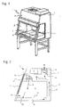
- FIGS 1 and 2 show a safety workbench (1) according to the invention, which can be used for example for processing microbiological cultures.
- the safety workbench (1) corresponds to what is known from the prior art.
- the safety workbench has a housing (2) which surrounds a working interior (3).
- By pushing down the front screen (5) located on the front of the housing work opening (6) can be reduced or completely closed.
- the height of the working opening (6) thus results from the gap between the underside of the windshield (5) and the working space bottom plate of the housing (2).
- the safety workbench (1) there are two blowers, namely an exhaust fan (7), which conveys a certain proportion by volume of the air (8) conveyed inside the safety workbench (1) as exhaust air flow (18) out of the safety workbench.
- the discharged exhaust air (18) is replaced by outside air (19), which flows through the working opening (6) in the working space (3) of the safety workbench (1).
- the air flow (8) through a circulating air blower (16) is conveyed through an opening (20) in the worktop (21) and through channels located in an area below the worktop (21) and behind the Working interior (3) limiting rear wall (22), transported air via a filter (23) from top to bottom in the direction of the worktop (21) leads out.
- the calibration procedure is shown here only for the exhaust fan (7).
- the calibration procedure is performed by the device control unit (9), which may be a control unit already present in a safety cabinet.
- a query is started in a processor, not shown, of the device control unit (9), in which it is checked whether a calibration procedure has already been carried out for the safety workbench.
- the answer to this query is coded in a software switch that is factory set to 0, which says that in this case no calibration has taken place yet.
- the calibration routine is started by the device control unit (9).
- the fan is started by means (10) integrated in the appliance control unit (9) for controlling the blower (7) and caused to run with a blower power preset for the normal operation of the safety workbench.
- the normal blower output is set to 70% of the maximum possible blower output. After a predetermined period of time since starting the fan (7) elapsed is, is determined by means of the measuring means (13), with which flow rate the fan (7) promotes air through the interior of the safety cabinet.
- the flow rate of the amount of air delivered by the blower (7) is determined in such a way that a pressure difference is measured, which builds up on the blower (7).
- a pressure cell (14) and (15) are arranged.
- Pressure cell (14) measures the pressure upstream of the blower (7)
- pressure box (15) measures the pressure downstream of the blower.
- Both pressure cans are arranged at a short distance from the blower (7).
- the determined pressure values are transmitted from the pressure cans (14) and (15) to an evaluation unit (12), which is arranged in the device control unit (9). In the evaluation unit (12), a pressure difference is calculated from the transmitted values, which is output to the memory unit (11) and stored there.
- the means (10) for controlling the fan (7) controls it so that the fan (7) runs at a power which corresponds to the predetermined lower limit of the fan power, i. H. the lower alarm limit, corresponds.
- the lower alarm limit may be set, for example, to a blower output of 60% of the maximum possible blower output.
- the fan power at the lower alarm limit is therefore 10% lower than during normal operation of the fan.
- an upper limit value corresponding to an upper alarm limit for the blower output is also stored for the blower (7), then this upper alarm limit is approached with the blower.
- the maximum allowable power of the blower may be set at 80% of the maximum blower output.
- the maximum permissible blower output is therefore 10% more than the normal output of the blower.
- the means (10) for controlling the upper alarm limit correction fan (7) now controls the blower (7) to operate at 80% of its maximum power. After a predetermined period of time pressure values are again measured with the pressure cans (14) and (15), these are subtracted from one another in the evaluation unit (12) in order to increase the pressure difference across the blower (7) result, and the calculated value is stored as an upper alarm limit in the memory unit (11).
- a safety monitoring system (17) is integrated in the device control unit (9).
- flow rate measurements are taken continuously or at fixed intervals. This happens here, as already during the calibration procedure, by determining pressure difference values for the blowers (7) and (16).
- the pressure difference data currently determined during operation are now compared with the values corrected by the calibration procedure. If a measured value determined for one of the blowers deviates from the permissible range defined by the corresponding alarm limits, an optical or acoustic alarm is triggered by the safety monitoring system (17).
- the alarm device (24) emits an alarm signal.
- the means (10) for controlling the fan (7), the memory unit (11), the evaluation unit (12) and the safety monitoring system (17) are all integrated in the device control unit (9).
- the individual components can also be installed separately from one another in the safety workbench (1). It is also possible for different control, evaluation or storage functions to be taken over by one and the same device, although separate components for this purpose are shown here.
- the resources required are in conventional systems of safety cabinets already existing, so that no additional components are needed, but they need only receive additional functionality.
- control unit can be performed.
- the first steps of the calibration procedure are identical to the previous procedure.
- the calibration procedures are the same. From the measuring process at normal fan power so a pressure difference is obtained, which corresponds to a flow velocity at the site of the safety cabinet.
- This pressure difference value is now compared in the evaluation unit (12) with a stored in the memory unit (11) pressure difference value for the fan at normal power, which corresponds to the fan power at the production of the safety cabinet.
- the pressure difference for the blower (7) at the manufacturing site of the safety cabinet was 50 Pa.
- the pressure difference for the blower during normal operation measured at the work site of the safety workbench during the calibration process is, for example, 40 Pa.
- This value is stored in the memory unit (11).
- pressure difference values for the fan (7) are stored, which were determined at the production site for the fan (7) at the upper and lower alarm limits. For example, for the fan (7) at reduced power, which corresponds to the lower alarm limit, a pressure difference of 35 Pa was determined. From this value, the determined difference value of 10 Pa is subtracted. This results in a corrected pressure difference value for the lower alarm limit of the blower (7) at the current location of 25 Pa.
- This ascertained corrected pressure difference value for the lower alarm limit is stored in the memory unit (11) and used as a new lower alarm limit during the safety monitoring by the safety monitoring unit (17) during the normal operation of the safety workbench.
- the same procedure is used for the upper alarm limit.
- the pressure difference value stored at the factory for the upper alarm limit is thus corrected downward by 10 Pa, stored and used as a new limit value (upper alarm limit) in the safety monitoring of the safety workbench during normal operation.
- the upper and lower alarm limits are therefore no longer actively approached and measured again, but only one measurement is carried out at normal fan power and, based on the determined deviation, a correction of the upper and lower alarm limits.
- the completion of the calibration procedure again corresponds to the method described above.
- the described calibration method can not only be started automatically when the safety workbench is first put into operation. It is also possible and useful to re-calibrate the alarm limits if repair work has been performed on the safety cabinet. This applies in particular to repair work which can influence the flow velocity within the safety workbench. By way of example, the replacement of filters, the replacement or the repair of blowers can be mentioned here.
- the switch set in the software which is set to 1 after initial operation of the safety cabinet and initial calibration, is reset to 0 so that the calibration routine can start.
- the calibration routine does not start automatically, but always has to be started manually. If required, authorizations can be assigned for this, so that only authorized persons can carry out a calibration.
Landscapes
- Ventilation (AREA)
- Forklifts And Lifting Vehicles (AREA)
Priority Applications (1)
| Application Number | Priority Date | Filing Date | Title |
|---|---|---|---|
| PL07021475T PL1935518T3 (pl) | 2006-12-21 | 2007-11-05 | Bezpieczne stanowisko robocze i sposób jego kalibrowania |
Applications Claiming Priority (1)
| Application Number | Priority Date | Filing Date | Title |
|---|---|---|---|
| DE102006060713A DE102006060713B3 (de) | 2006-12-21 | 2006-12-21 | Sicherheitswerkbank und Verfahren zum Kalibrieren derselben |
Publications (2)
| Publication Number | Publication Date |
|---|---|
| EP1935518A1 true EP1935518A1 (fr) | 2008-06-25 |
| EP1935518B1 EP1935518B1 (fr) | 2012-10-10 |
Family
ID=39110475
Family Applications (1)
| Application Number | Title | Priority Date | Filing Date |
|---|---|---|---|
| EP07021475A Active EP1935518B1 (fr) | 2006-12-21 | 2007-11-05 | Etabli de sécurité et son procédé de calibrage |
Country Status (7)
| Country | Link |
|---|---|
| US (1) | US10307802B2 (fr) |
| EP (1) | EP1935518B1 (fr) |
| CN (1) | CN101204711B (fr) |
| DE (1) | DE102006060713B3 (fr) |
| DK (1) | DK1935518T3 (fr) |
| ES (1) | ES2397404T3 (fr) |
| PL (1) | PL1935518T3 (fr) |
Cited By (1)
| Publication number | Priority date | Publication date | Assignee | Title |
|---|---|---|---|---|
| CN104907110A (zh) * | 2015-05-21 | 2015-09-16 | 蚌埠市瑞风净化设备工程有限责任公司 | 一种便于使用的生物安全柜 |
Families Citing this family (13)
| Publication number | Priority date | Publication date | Assignee | Title |
|---|---|---|---|---|
| DE102006060713B3 (de) * | 2006-12-21 | 2008-06-12 | Thermo Electron Led Gmbh | Sicherheitswerkbank und Verfahren zum Kalibrieren derselben |
| GB2499469A (en) * | 2012-02-15 | 2013-08-21 | Safehouse Habitats Scotland Ltd | Control System for a Hot Work Habitat |
| KR102007899B1 (ko) * | 2014-12-31 | 2019-08-07 | 대구한의대학교산학협력단 | 실험실 흄후드 |
| CN105728066B (zh) * | 2016-03-01 | 2017-12-01 | 南京汉尔斯生物科技有限公司 | 净气药品柜抽风功率调节装置及其调节方法 |
| DE102016109301A1 (de) * | 2016-05-20 | 2017-11-23 | Ebm-Papst Mulfingen Gmbh & Co. Kg | Vorrichtung zur Reduzierung einer Anzahl an Festkörperpartikeln aus der Umgebungsluft |
| DE102016124495A1 (de) * | 2016-12-15 | 2018-06-21 | Rheinmetall Man Military Vehicles Gmbh | Sicherheitswerkbank, mobiles Labor und Verfahren |
| US20190329305A1 (en) * | 2018-04-25 | 2019-10-31 | Timothy McKibben | Fume hood air channeling device |
| DE102018004587B3 (de) * | 2018-06-08 | 2019-08-22 | Thermo Electron Led Gmbh | Sicherheitswerkbank mit geregeltem Umluftstrom sowie Verfahren zu deren Betrieb |
| WO2021072074A1 (fr) | 2019-10-10 | 2021-04-15 | Coopersurgical, Inc. | Postes de travail configurables |
| CN112170433A (zh) * | 2020-10-20 | 2021-01-05 | 上海木雅实验室设备有限公司 | 一种实验室用通风柜 |
| CN113547386B (zh) * | 2021-07-07 | 2023-07-04 | 合肥亿恒智能科技有限公司 | 基于感应机构的接地片组件加工用机床 |
| CN114306799B (zh) * | 2022-03-10 | 2022-07-12 | 济南鑫贝西生物技术有限公司 | 一种水平流配药洁净工作台 |
| DE102024001496A1 (de) * | 2024-05-08 | 2025-11-13 | Imm Cleaning Solutions Gmbh | System und Verfahren zum qualitätssicheren Reinigen von Werkstücken und/oder Werkzeugen |
Citations (3)
| Publication number | Priority date | Publication date | Assignee | Title |
|---|---|---|---|---|
| US4528898A (en) * | 1984-03-05 | 1985-07-16 | Imec Corporation | Fume hood controller |
| US5405291A (en) * | 1993-11-24 | 1995-04-11 | Voltec Incorporated | Adaptive feedforward laboratory controller with proportional/integral calculation |
| US5562537A (en) * | 1995-05-11 | 1996-10-08 | Landis & Gyr Powers, Inc. | Networked fume hood monitoring system |
Family Cites Families (15)
| Publication number | Priority date | Publication date | Assignee | Title |
|---|---|---|---|---|
| US4466341A (en) * | 1982-12-17 | 1984-08-21 | Grogan Dennis R | Fume hood energy controller |
| US4741257A (en) * | 1985-01-09 | 1988-05-03 | Air Monitor Corporation | Fume hood air flow control |
| US5092227B1 (en) * | 1990-09-28 | 1995-02-14 | Landis & Gyr Powers Inc | Apparatus for controlling the ventilation of laboratory fume hoods |
| US5090303A (en) * | 1990-09-28 | 1992-02-25 | Landis & Gyr Powers, Inc. | Laboratory fume hood control apparatus having improved safety considerations |
| US5946221A (en) * | 1994-09-07 | 1999-08-31 | American Auto-Matrix, Inc. | Method and system for maintaining a desired air flow through a fume hood |
| DE4441784C2 (de) * | 1994-11-25 | 1997-05-28 | Heraeus Instr Gmbh | Sicherheitswerkbank |
| CN2370827Y (zh) * | 1999-01-07 | 2000-03-29 | 胡兆丰 | 生物安全工作台 |
| DE10217904C1 (de) * | 2002-04-22 | 2003-10-02 | Kendro Lab Prod Gmbh | Sicherheitswerkbank mit Sicherheitsüberwachungssystem |
| US6914532B2 (en) * | 2003-07-30 | 2005-07-05 | Honeywell International Inc. | Method and apparatus for alarm verification in a ventilation system |
| US7001263B2 (en) * | 2003-08-14 | 2006-02-21 | Cornell Research Foundation, Inc. | Air flow monitoring and control system with reduced false alarms |
| CA2571268C (fr) * | 2004-06-22 | 2010-05-18 | Oy Halton Group Ltd. | Controleur d'expulsion a pose facile |
| DE102004032454A1 (de) * | 2004-06-24 | 2006-01-12 | Kendro Laboratory Products Gmbh | Sicherheitswerkbank |
| US20070026786A1 (en) * | 2005-07-22 | 2007-02-01 | Mingsheng Liu | Variable source diameter stack system and method |
| DE102006053122B4 (de) * | 2006-11-10 | 2008-09-25 | Thermo Electron Led Gmbh | Sicherheitswerkbank mit in Abhängigkeit der Frontscheibenposition steuerbarer Gebläseleistung |
| DE102006060713B3 (de) * | 2006-12-21 | 2008-06-12 | Thermo Electron Led Gmbh | Sicherheitswerkbank und Verfahren zum Kalibrieren derselben |
-
2006
- 2006-12-21 DE DE102006060713A patent/DE102006060713B3/de active Active
-
2007
- 2007-11-05 EP EP07021475A patent/EP1935518B1/fr active Active
- 2007-11-05 ES ES07021475T patent/ES2397404T3/es active Active
- 2007-11-05 PL PL07021475T patent/PL1935518T3/pl unknown
- 2007-11-05 DK DK07021475.4T patent/DK1935518T3/da active
- 2007-12-20 US US11/961,923 patent/US10307802B2/en active Active
- 2007-12-21 CN CN2007103015032A patent/CN101204711B/zh active Active
Patent Citations (3)
| Publication number | Priority date | Publication date | Assignee | Title |
|---|---|---|---|---|
| US4528898A (en) * | 1984-03-05 | 1985-07-16 | Imec Corporation | Fume hood controller |
| US5405291A (en) * | 1993-11-24 | 1995-04-11 | Voltec Incorporated | Adaptive feedforward laboratory controller with proportional/integral calculation |
| US5562537A (en) * | 1995-05-11 | 1996-10-08 | Landis & Gyr Powers, Inc. | Networked fume hood monitoring system |
Cited By (1)
| Publication number | Priority date | Publication date | Assignee | Title |
|---|---|---|---|---|
| CN104907110A (zh) * | 2015-05-21 | 2015-09-16 | 蚌埠市瑞风净化设备工程有限责任公司 | 一种便于使用的生物安全柜 |
Also Published As
| Publication number | Publication date |
|---|---|
| PL1935518T3 (pl) | 2013-03-29 |
| DK1935518T3 (da) | 2012-12-10 |
| CN101204711A (zh) | 2008-06-25 |
| US10307802B2 (en) | 2019-06-04 |
| CN101204711B (zh) | 2010-06-23 |
| US20080318509A1 (en) | 2008-12-25 |
| DE102006060713B3 (de) | 2008-06-12 |
| ES2397404T3 (es) | 2013-03-06 |
| EP1935518B1 (fr) | 2012-10-10 |
Similar Documents
| Publication | Publication Date | Title |
|---|---|---|
| EP1935518B1 (fr) | Etabli de sécurité et son procédé de calibrage | |
| EP3578274B1 (fr) | Poste de sécurité biologique à flux d'air de circulation régulé ainsi que son procédé de fonctionnement | |
| EP1609541B1 (fr) | Établi de sécurité | |
| DE102017219353B4 (de) | Serviceeinheit für eine fahrzeug-klimaanlage und verfahren zum betreiben einer serviceeinheit | |
| EP1406048B1 (fr) | Dispositif de surveillance de la pollution de l'air de locaux | |
| EP1920891A1 (fr) | Etabli de sécurité avec puissance de ventilateur pouvant être commandée en fonction de la position de la plaque avant | |
| EP2893945A1 (fr) | Machine de traitement de sang extracorporel à détection de fuites et procédé de détection de fuites dans des systèmes de liquides de dialyse | |
| WO2015051897A1 (fr) | Appareil filtrant à ventilation assistée, système de protection respiratoire et procédé | |
| DE19652372A1 (de) | Pneumatische Belastungsvorrichtung eines Streckwerkes in einer Spinnmaschine | |
| EP1935516B1 (fr) | Etabli de sécurité doté d'une cuve au sol à double paroi | |
| EP0453909B1 (fr) | Procédé pour le positionnement et le réglage d'une plieuse | |
| DE19850225A1 (de) | Vorrichtung zum Erfassen des Zustands bzw. des Endes der Gebrauchsdauer eines Filterelements | |
| EP3002525B1 (fr) | Procede destine au fonctionnement d'une installation de ventilation et installation de ventilation | |
| EP1356873B1 (fr) | Etabli de sécurité avec système de surveillance de sécurité | |
| EP3305513A1 (fr) | Presse pour panneaux en matériaux dérivés du bois et procédé de surveillance d'une telle presse pour panneaux en matériaux dérivés du bois | |
| EP2636964B1 (fr) | Procédé de surveillance de la qualité d'air dans une salle d'opération | |
| EP1638062B1 (fr) | Détecteur de fumée à aspiration et méthode de son fonctionnement | |
| AT509770B1 (de) | Mobile sterilluftversorgungseinrichtung | |
| DE102022201026A1 (de) | Luftmanagement-System und Verfahren zum Steuern einer Luftzufuhr eines Innenraums | |
| DE10317471B3 (de) | Verfahren zur Entlüftung eines Gebäudes, sowie Entlüftungsanlage für ein Gebäude | |
| DE20309818U1 (de) | Vorrichtung zum Ermitteln des Luftdurchgangswiderstands eines Luftfilters | |
| DE102021104187B4 (de) | Kontrollverfahren für die Faltschachtelproduktion, insbesondere bezüglich des Klebeauftrags | |
| EP2815844A1 (fr) | Réglage de l'épaisseur pour meuleuses | |
| EP4306195B1 (fr) | Procédé de modification du débit volumique d'un fluide gazeux | |
| WO2018153501A1 (fr) | Dispositif et procédé d'échange d'un gaz présent dans une chambre de travail d'une enceinte à gaz inerte accessible |
Legal Events
| Date | Code | Title | Description |
|---|---|---|---|
| PUAI | Public reference made under article 153(3) epc to a published international application that has entered the european phase |
Free format text: ORIGINAL CODE: 0009012 |
|
| 17P | Request for examination filed |
Effective date: 20080421 |
|
| AK | Designated contracting states |
Kind code of ref document: A1 Designated state(s): AT BE BG CH CY CZ DE DK EE ES FI FR GB GR HU IE IS IT LI LT LU LV MC MT NL PL PT RO SE SI SK TR |
|
| AX | Request for extension of the european patent |
Extension state: AL BA HR MK RS |
|
| AKX | Designation fees paid |
Designated state(s): AT BE BG CH CY CZ DE DK EE ES FI FR GB GR HU IE IS IT LI LT LU LV MC MT NL PL PT RO SE SI SK TR |
|
| GRAP | Despatch of communication of intention to grant a patent |
Free format text: ORIGINAL CODE: EPIDOSNIGR1 |
|
| GRAS | Grant fee paid |
Free format text: ORIGINAL CODE: EPIDOSNIGR3 |
|
| GRAA | (expected) grant |
Free format text: ORIGINAL CODE: 0009210 |
|
| AK | Designated contracting states |
Kind code of ref document: B1 Designated state(s): AT BE BG CH CY CZ DE DK EE ES FI FR GB GR HU IE IS IT LI LT LU LV MC MT NL PL PT RO SE SI SK TR |
|
| REG | Reference to a national code |
Ref country code: GB Ref legal event code: FG4D Free format text: NOT ENGLISH |
|
| REG | Reference to a national code |
Ref country code: AT Ref legal event code: REF Ref document number: 578704 Country of ref document: AT Kind code of ref document: T Effective date: 20121015 Ref country code: CH Ref legal event code: EP |
|
| REG | Reference to a national code |
Ref country code: IE Ref legal event code: FG4D Free format text: LANGUAGE OF EP DOCUMENT: GERMAN |
|
| REG | Reference to a national code |
Ref country code: DK Ref legal event code: T3 |
|
| REG | Reference to a national code |
Ref country code: DE Ref legal event code: R096 Ref document number: 502007010665 Country of ref document: DE Effective date: 20121213 |
|
| PG25 | Lapsed in a contracting state [announced via postgrant information from national office to epo] |
Ref country code: SI Free format text: LAPSE BECAUSE OF FAILURE TO SUBMIT A TRANSLATION OF THE DESCRIPTION OR TO PAY THE FEE WITHIN THE PRESCRIBED TIME-LIMIT Effective date: 20121010 |
|
| REG | Reference to a national code |
Ref country code: ES Ref legal event code: FG2A Ref document number: 2397404 Country of ref document: ES Kind code of ref document: T3 Effective date: 20130306 |
|
| REG | Reference to a national code |
Ref country code: NL Ref legal event code: VDEP Effective date: 20121010 |
|
| REG | Reference to a national code |
Ref country code: LT Ref legal event code: MG4D |
|
| REG | Reference to a national code |
Ref country code: PL Ref legal event code: T3 |
|
| PG25 | Lapsed in a contracting state [announced via postgrant information from national office to epo] |
Ref country code: NL Free format text: LAPSE BECAUSE OF FAILURE TO SUBMIT A TRANSLATION OF THE DESCRIPTION OR TO PAY THE FEE WITHIN THE PRESCRIBED TIME-LIMIT Effective date: 20121010 Ref country code: LT Free format text: LAPSE BECAUSE OF FAILURE TO SUBMIT A TRANSLATION OF THE DESCRIPTION OR TO PAY THE FEE WITHIN THE PRESCRIBED TIME-LIMIT Effective date: 20121010 Ref country code: FI Free format text: LAPSE BECAUSE OF FAILURE TO SUBMIT A TRANSLATION OF THE DESCRIPTION OR TO PAY THE FEE WITHIN THE PRESCRIBED TIME-LIMIT Effective date: 20121010 Ref country code: IS Free format text: LAPSE BECAUSE OF FAILURE TO SUBMIT A TRANSLATION OF THE DESCRIPTION OR TO PAY THE FEE WITHIN THE PRESCRIBED TIME-LIMIT Effective date: 20130210 Ref country code: SE Free format text: LAPSE BECAUSE OF FAILURE TO SUBMIT A TRANSLATION OF THE DESCRIPTION OR TO PAY THE FEE WITHIN THE PRESCRIBED TIME-LIMIT Effective date: 20121010 |
|
| BERE | Be: lapsed |
Owner name: THERMO ELECTRON LED G.M.B.H. Effective date: 20121130 |
|
| PG25 | Lapsed in a contracting state [announced via postgrant information from national office to epo] |
Ref country code: GR Free format text: LAPSE BECAUSE OF FAILURE TO SUBMIT A TRANSLATION OF THE DESCRIPTION OR TO PAY THE FEE WITHIN THE PRESCRIBED TIME-LIMIT Effective date: 20130111 Ref country code: PT Free format text: LAPSE BECAUSE OF FAILURE TO SUBMIT A TRANSLATION OF THE DESCRIPTION OR TO PAY THE FEE WITHIN THE PRESCRIBED TIME-LIMIT Effective date: 20130211 Ref country code: CY Free format text: LAPSE BECAUSE OF FAILURE TO SUBMIT A TRANSLATION OF THE DESCRIPTION OR TO PAY THE FEE WITHIN THE PRESCRIBED TIME-LIMIT Effective date: 20121010 Ref country code: LV Free format text: LAPSE BECAUSE OF FAILURE TO SUBMIT A TRANSLATION OF THE DESCRIPTION OR TO PAY THE FEE WITHIN THE PRESCRIBED TIME-LIMIT Effective date: 20121010 |
|
| REG | Reference to a national code |
Ref country code: CH Ref legal event code: PL |
|
| PG25 | Lapsed in a contracting state [announced via postgrant information from national office to epo] |
Ref country code: EE Free format text: LAPSE BECAUSE OF FAILURE TO SUBMIT A TRANSLATION OF THE DESCRIPTION OR TO PAY THE FEE WITHIN THE PRESCRIBED TIME-LIMIT Effective date: 20121010 Ref country code: BG Free format text: LAPSE BECAUSE OF FAILURE TO SUBMIT A TRANSLATION OF THE DESCRIPTION OR TO PAY THE FEE WITHIN THE PRESCRIBED TIME-LIMIT Effective date: 20130110 Ref country code: LI Free format text: LAPSE BECAUSE OF NON-PAYMENT OF DUE FEES Effective date: 20121130 Ref country code: CH Free format text: LAPSE BECAUSE OF NON-PAYMENT OF DUE FEES Effective date: 20121130 Ref country code: SK Free format text: LAPSE BECAUSE OF FAILURE TO SUBMIT A TRANSLATION OF THE DESCRIPTION OR TO PAY THE FEE WITHIN THE PRESCRIBED TIME-LIMIT Effective date: 20121010 |
|
| REG | Reference to a national code |
Ref country code: IE Ref legal event code: MM4A |
|
| PLBE | No opposition filed within time limit |
Free format text: ORIGINAL CODE: 0009261 |
|
| STAA | Information on the status of an ep patent application or granted ep patent |
Free format text: STATUS: NO OPPOSITION FILED WITHIN TIME LIMIT |
|
| PG25 | Lapsed in a contracting state [announced via postgrant information from national office to epo] |
Ref country code: RO Free format text: LAPSE BECAUSE OF FAILURE TO SUBMIT A TRANSLATION OF THE DESCRIPTION OR TO PAY THE FEE WITHIN THE PRESCRIBED TIME-LIMIT Effective date: 20121010 Ref country code: BE Free format text: LAPSE BECAUSE OF NON-PAYMENT OF DUE FEES Effective date: 20121130 |
|
| 26N | No opposition filed |
Effective date: 20130711 |
|
| PG25 | Lapsed in a contracting state [announced via postgrant information from national office to epo] |
Ref country code: IE Free format text: LAPSE BECAUSE OF NON-PAYMENT OF DUE FEES Effective date: 20121105 |
|
| REG | Reference to a national code |
Ref country code: DE Ref legal event code: R097 Ref document number: 502007010665 Country of ref document: DE Effective date: 20130711 |
|
| PG25 | Lapsed in a contracting state [announced via postgrant information from national office to epo] |
Ref country code: MT Free format text: LAPSE BECAUSE OF FAILURE TO SUBMIT A TRANSLATION OF THE DESCRIPTION OR TO PAY THE FEE WITHIN THE PRESCRIBED TIME-LIMIT Effective date: 20121010 |
|
| PG25 | Lapsed in a contracting state [announced via postgrant information from national office to epo] |
Ref country code: MC Free format text: LAPSE BECAUSE OF NON-PAYMENT OF DUE FEES Effective date: 20121130 |
|
| PG25 | Lapsed in a contracting state [announced via postgrant information from national office to epo] |
Ref country code: LU Free format text: LAPSE BECAUSE OF NON-PAYMENT OF DUE FEES Effective date: 20121105 |
|
| PG25 | Lapsed in a contracting state [announced via postgrant information from national office to epo] |
Ref country code: HU Free format text: LAPSE BECAUSE OF FAILURE TO SUBMIT A TRANSLATION OF THE DESCRIPTION OR TO PAY THE FEE WITHIN THE PRESCRIBED TIME-LIMIT Effective date: 20071105 |
|
| REG | Reference to a national code |
Ref country code: FR Ref legal event code: PLFP Year of fee payment: 9 |
|
| REG | Reference to a national code |
Ref country code: FR Ref legal event code: PLFP Year of fee payment: 10 |
|
| REG | Reference to a national code |
Ref country code: FR Ref legal event code: PLFP Year of fee payment: 11 |
|
| REG | Reference to a national code |
Ref country code: FR Ref legal event code: PLFP Year of fee payment: 12 |
|
| REG | Reference to a national code |
Ref country code: DE Ref legal event code: R082 Ref document number: 502007010665 Country of ref document: DE Representative=s name: BOULT WADE TENNANT LLP, DE Ref country code: DE Ref legal event code: R082 Ref document number: 502007010665 Country of ref document: DE |
|
| REG | Reference to a national code |
Ref country code: DE Ref legal event code: R082 Ref document number: 502007010665 Country of ref document: DE Representative=s name: BOULT WADE TENNANT LLP, DE |
|
| PGFP | Annual fee paid to national office [announced via postgrant information from national office to epo] |
Ref country code: DE Payment date: 20251010 Year of fee payment: 19 |
|
| PGFP | Annual fee paid to national office [announced via postgrant information from national office to epo] |
Ref country code: GB Payment date: 20251114 Year of fee payment: 19 |
|
| PGFP | Annual fee paid to national office [announced via postgrant information from national office to epo] |
Ref country code: AT Payment date: 20251010 Year of fee payment: 19 |
|
| PGFP | Annual fee paid to national office [announced via postgrant information from national office to epo] |
Ref country code: DK Payment date: 20251124 Year of fee payment: 19 Ref country code: IT Payment date: 20251010 Year of fee payment: 19 |
|
| PGFP | Annual fee paid to national office [announced via postgrant information from national office to epo] |
Ref country code: FR Payment date: 20251111 Year of fee payment: 19 |
|
| PGFP | Annual fee paid to national office [announced via postgrant information from national office to epo] |
Ref country code: TR Payment date: 20251105 Year of fee payment: 19 |
|
| PGFP | Annual fee paid to national office [announced via postgrant information from national office to epo] |
Ref country code: CZ Payment date: 20251029 Year of fee payment: 19 |
|
| PGFP | Annual fee paid to national office [announced via postgrant information from national office to epo] |
Ref country code: PL Payment date: 20251017 Year of fee payment: 19 |
|
| PGFP | Annual fee paid to national office [announced via postgrant information from national office to epo] |
Ref country code: ES Payment date: 20251211 Year of fee payment: 19 |