EP1935542B1 - Machine-outil dotée d'un dispositif d'arrêt et de serrage - Google Patents
Machine-outil dotée d'un dispositif d'arrêt et de serrage Download PDFInfo
- Publication number
- EP1935542B1 EP1935542B1 EP20070021014 EP07021014A EP1935542B1 EP 1935542 B1 EP1935542 B1 EP 1935542B1 EP 20070021014 EP20070021014 EP 20070021014 EP 07021014 A EP07021014 A EP 07021014A EP 1935542 B1 EP1935542 B1 EP 1935542B1
- Authority
- EP
- European Patent Office
- Prior art keywords
- clamping
- locking
- machine tool
- operating
- clamp
- Prior art date
- Legal status (The legal status is an assumption and is not a legal conclusion. Google has not performed a legal analysis and makes no representation as to the accuracy of the status listed.)
- Active
Links
- 210000003811 finger Anatomy 0.000 claims description 10
- 238000005520 cutting process Methods 0.000 claims description 7
- 238000000151 deposition Methods 0.000 claims description 2
- 210000003813 thumb Anatomy 0.000 claims description 2
- 238000003754 machining Methods 0.000 description 2
- 208000027418 Wounds and injury Diseases 0.000 description 1
- 230000006378 damage Effects 0.000 description 1
- 239000000428 dust Substances 0.000 description 1
- 210000005224 forefinger Anatomy 0.000 description 1
- 208000014674 injury Diseases 0.000 description 1
- 230000002093 peripheral effect Effects 0.000 description 1
- 238000003825 pressing Methods 0.000 description 1
- 239000004575 stone Substances 0.000 description 1
- 238000003860 storage Methods 0.000 description 1
- 239000000758 substrate Substances 0.000 description 1
Images


Classifications
-
- B—PERFORMING OPERATIONS; TRANSPORTING
- B27—WORKING OR PRESERVING WOOD OR SIMILAR MATERIAL; NAILING OR STAPLING MACHINES IN GENERAL
- B27B—SAWS FOR WOOD OR SIMILAR MATERIAL; COMPONENTS OR ACCESSORIES THEREFOR
- B27B5/00—Sawing machines working with circular or cylindrical saw blades; Components or equipment therefor
- B27B5/29—Details; Component parts; Accessories
-
- B—PERFORMING OPERATIONS; TRANSPORTING
- B23—MACHINE TOOLS; METAL-WORKING NOT OTHERWISE PROVIDED FOR
- B23D—PLANING; SLOTTING; SHEARING; BROACHING; SAWING; FILING; SCRAPING; LIKE OPERATIONS FOR WORKING METAL BY REMOVING MATERIAL, NOT OTHERWISE PROVIDED FOR
- B23D45/00—Sawing machines or sawing devices with circular saw blades or with friction saw discs
- B23D45/04—Sawing machines or sawing devices with circular saw blades or with friction saw discs with a circular saw blade or the stock carried by a pivoted lever
- B23D45/042—Sawing machines or sawing devices with circular saw blades or with friction saw discs with a circular saw blade or the stock carried by a pivoted lever with the saw blade carried by a pivoted lever
- B23D45/046—Sawing machines or sawing devices with circular saw blades or with friction saw discs with a circular saw blade or the stock carried by a pivoted lever with the saw blade carried by a pivoted lever the pivoted lever being mounted on a carriage
- B23D45/048—Sawing machines or sawing devices with circular saw blades or with friction saw discs with a circular saw blade or the stock carried by a pivoted lever with the saw blade carried by a pivoted lever the pivoted lever being mounted on a carriage the saw blade being adjustable according to angle of cut
-
- B—PERFORMING OPERATIONS; TRANSPORTING
- B23—MACHINE TOOLS; METAL-WORKING NOT OTHERWISE PROVIDED FOR
- B23D—PLANING; SLOTTING; SHEARING; BROACHING; SAWING; FILING; SCRAPING; LIKE OPERATIONS FOR WORKING METAL BY REMOVING MATERIAL, NOT OTHERWISE PROVIDED FOR
- B23D47/00—Sawing machines or sawing devices working with circular saw blades, characterised only by constructional features of particular parts
- B23D47/02—Sawing machines or sawing devices working with circular saw blades, characterised only by constructional features of particular parts of frames; of guiding arrangements for work-table or saw-carrier
- B23D47/025—Sawing machines or sawing devices working with circular saw blades, characterised only by constructional features of particular parts of frames; of guiding arrangements for work-table or saw-carrier of tables
Definitions
- the invention relates to a machine tool, in particular a saw, for the separating machining of a workpiece, according to the preamble of claim 1.
- a machine tool in the form of a hacksaw with a capping table is from the DE 198 03 955 A1 known.
- a turntable for placing a workpiece is mounted rotatably or pivotably on a capping table. According to the angular position of the turntable, miter cuts can be made with the hoist saw.
- a latching device provides detent positions for different angular positions of the turntable.
- a clamping screw serves as a clamping device and allows a free setting of the pivoting part or turntable at angular positions between the latchable angular positions.
- the arbitrary angles of the pivoting part are only infinitely adjustable when the release button is kept pressed, so that the locking device is not locked in the region of the locking positions.
- the clamping screw or clamping device is according to the selected angular position of Turntable locked.
- the clamping screw and the unlocking button are inconvenient to use.
- the locking actuating handle and the clamping actuating handle can be operated with one hand. Thereby, it is easily possible to hold the latching actuating handle in the latch release position while the clamping device is operated.
- the locking actuating handle is moved relative to the clamping actuating handle to achieve the locking release position.
- the detent actuating lever is pivotally mounted on the clamping actuating lever.
- the lever axis is advantageously located in a central portion of the clamping actuating lever. This in turn is suitably pivotally mounted in front, in the region of its actuating part.
- the clamp operating lever has a longer lever arm as the latching lever. From the common lever axis of the two actuating lever, however, the operating parts of the locking actuating lever and the clamping operating lever each advantageously have the same lever spacing.
- the common lever axis of the locking actuating lever and the clamping actuating lever expediently have a longitudinal distance to a pivot axis of the clamping actuating lever.
- the actuating part of the locking actuating lever and a pivot bearing of the clamping actuating lever are advantageously arranged close to each other.
- the actuating portion of the detent actuating lever is adjacent to the pivotal mounting of the clamping actuating lever, e.g. a Kerblagerung arranged.
- the pivotal mounting of the clamping actuating lever and the actuating part of the latching actuating lever, in particular when it assumes its latching release position, are arranged next to one another, for example, in the axial direction of the pivot axis of the clamping actuating lever.
- the actuating part is positioned between two pivot bearing portions of the clamping operating lever.
- the machine tool is expediently a miter saw.
- the application of the invention miter miter saws or miter saws is advantageous.
- the cutting tool can also be a cutting disk, for example for cutting tiles, stone or the like.
- the latching device and the clamping device are expediently arranged on the pivoting part, while the latching base and the clamping base are arranged on the pivoting base.
- the latching device and the clamping device can also be arranged on the non-rotatable pivoting base and the latching base and the clamping base on the pivotable part.
- the pivoting part is, for example, a workpiece table for depositing a workpiece.
- the swivel base or swivel base conveniently comprises a machine bed in this case.
- the pivoting part may also be a pivotable stop of a workpiece table.
- the pivoting part forms a pivoting carrier for pivoting a separating device or sawing device of the machine tool, wherein the separating device or sawing device contains a tool drivable by a drive motor.
- the separating or sawing device can be brought into the desired angular position or pivoting position with one hand.
- the latching device and the clamping device can form components of an integrated holding device. Furthermore, the latching device and the clamping device can be arranged in a housing of the pivoting part, for example the workpiece table or the pivoting carrier.
- the clamping actuating handle advantageously contains a handpiece which can be grasped by hand.
- the latching actuating handle can be, for example, a finger actuating piece that can be actuated with a finger include.
- the operator can embrace the handpiece and at the same time hold the finger operating piece with a finger, for example his or her thumb or forefinger, in the detent release position or detent release position.
- the latching actuating handle includes an operating projection, which engages around when grasping the handpiece of the clamping actuating handle and thus, so to speak, is automatically actuated in the direction of the latch release position.
- the latching base advantageously contains arcuately arranged latching receptacles or latching projections.
- the locking receptacles are arranged on a plate-like arch part.
- the clamping base it is advantageous if it is formed by a preferably plate-like arch part.
- the latching base and the clamping base are formed by two separate sheet parts.
- the clamping base and the latching base are formed by a single plate-like arched part.
- the latching receptacles or latching projections can also be arranged, for example, on a housing or housing body of the pivoting base.
- the clamping device or the latching device are expediently in the direction of their respective clamping or latching position spring-loaded. Then the clamping actuator and the latch actuator are only required to bring the clamping device or the latching device in their respective release position. The provision in the respective holding position takes place automatically.
- the clamping device includes a preferably spring-loaded in the direction of the clamping position, actuatable by the clamping actuator clamping member for clamping with the clamping base. Also this clamping part can be resilient. Furthermore, it is possible that the clamping part is spring-loaded by a spring arrangement in the direction of the clamping position.
- the clamping part is e.g. plate-like part.
- the latching part and the clamping part expediently act from opposite sides on the latching base and the clamping base.
- the clamping device for example the clamping actuator is expediently fixed in the clamping position or the clamping release position, e.g. with a latching arrangement or a locking device. It is conceivable that the clamping device can only be fixed in one of the two positions, e.g. in the clamping position, or in both positions.
- the latching device it is also advantageous if it can be fixed in the latching position or the latch release position.
- the setting may e.g. be effected by a spring which acts on the latching device in the detent position.
- the latching device can be latched in the latching position or the latch release position by means of a latching arrangement. Although this is not realized in the embodiment.
- corresponding locking projections or locking receptacles a locking of the locking device in the locking position and / or the locking release position is readily possible.
- the clamping actuating lever is expediently mounted pivotably in the region of its actuating part.
- the clamping actuating lever is mounted on a housing. It is advantageous Kerblagerung. Due to the storage in the area of the actuating part, a long lever arm is available, so that the clamping of the clamping device can be easily canceled even if it clamps the pivoting part on the clamping base with a large clamping force, for example with a strong spring.
- Locking arrangements for holding the actuating lever in its respective position are expediently arranged on the latching actuating lever and / or on the clamping actuating lever.
- the actuating lever then remains in the release position or the holding position.
- the latching arrangements are arranged in the region of the respective actuating part of the actuating lever.
- corresponding latching arrangements can be arranged.
- a variant is realized in which engages a locking arrangement of the clamping actuating lever in the locking position in a recess on the clamping part.
- the sliding arrangement slides, for example, along the clamping part or locking part. The roller rolls on the locking part or clamping part.
- the saw 10 By turning or pivoting the sawing device 11 about the axis of rotation 17 with respect to a vertical stop 16 miter cuts can be performed.
- the saw 10 performs the function of a miter saw.
- the ability to pivot the sawing device 11 about the pivot axis 19 makes the saw 10 to a chop saw.
- By oblique pivoting of the sawing device 11 about the inclined pivot axis 18 oblique cuts are possible.
- a substantially cylindrical work table body 26 of the pivot member 24 is rotatably received between workpiece table projections projecting laterally upward in front of a bottom portion 28 of the pivot base 23. Upper sides of the body 26 and the projections 27 form a bearing surface 29 of a workpiece table 30 for placing the workpiece 15.
- Radially inner front sides of the projections 27 are corresponding to the round outer periphery of the body 26 around.
- Vertical side surfaces 31 of the projections 27 form pivot stops for an actuating arm 32 of the pivoting part 24, which protrudes radially outward in front of the body 26.
- a kerf 33 extends on bearing surface 29 of the body 26 approximately from the axis of rotation 17 to the radially outer, free end of the actuating arm 32.
- the upper side of the actuating arm 32 forms a bearing surface of the workpiece table 30th
- a stop member 34 is arranged on the stop plates 35 to form the vertical stop 16 are fastened. Between the stop plates 35 a space is available.
- a latching actuating handle 42 and a clamping actuating handle 43 project radially outward in front of the actuating arm 32 of a latching actuator 44 and a clamping actuator 45. At least the clamping actuating handle 43 forms an operating handle for pivoting the pivoting part 24. With the actuators 44, 45, the latching device 36 and the clamping device 37 between a pivotal part on the pivot base 23 rotatably holding stop position and a pivoting enabling release position can be adjusted.
- the actuating handles 42, 43 are arranged directly next to one another.
- the clamping actuator can be adjusted between a terminal release position and a clamping position, while the same hand holds the latch actuator in the latch release position, so that the latching device 36 is not locked to the latching base 38.
- a swivel angle is thus freely selectable, even between locking positions of the locking device.
- the sawing device 11 is pivotably mounted on the saw carriage 58 about the cap pivot axis 19 on a pivot bearing 60.
- the sawing device 11 can be gripped by an operator on a handle 61 on its housing 62 and pivoted about the cap pivot axis 19 or pulled along the linear guide axis 21.
- a saw guard 63 is pivotally mounted on the housing 62, which protects against injury by the saw blade 12, but when sawing pivots into the housing 62 and the saw blade 12 releases.
- a suction connection 64 dust occurring during sawing can be sucked off.
- the oblique pivot gear 54 can be operated from the front side of the saw 10.
- a shaft 65, which leads to the oblique pivoting gear 54, of an actuating device 66 of the oblique pivoting gear 54 is arranged in an inner space of the guide tube 56 which is on the right in the drawing.
- a handle 67 projects in front of the front, free end of the guide tube 56 and can be conveniently gripped and rotated by an operator. According to the direction of rotation when turning the handle 67, the oblique pivoting gear 54 pivots the pivoting carrier 48 about the inclined pivot axis 18.
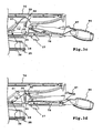
- the latching actuating device 44 includes a latching actuating lever 68, the clamping actuator 45 a clamping actuating lever 69. At the respective front, free ends of the actuating lever 68, 69 are actuating parts 70, 71 for actuating a latching part 72 and a clamping part 73rd
- the locking part 72 and the clamping part 73 are resilient stamped and bent parts.
- the locking part 72 and the clamping part 73 are biased in their respective holding position.
- the latching part 72 and the clamping part 73 are fastened, for example, to a housing 76 of the actuating arm 32.
- mounting holes 77 are provided.
- the clamping part 73 is supported on a housing projection 78 of the housing 76.
- the housing projection 78 protrudes downwards.
- the clamping part 73 is supported with its rear side on the housing projection 78. While the locking member 72 engages from above into the recesses 74, the clamping member 73 clamps the clamping base 39 from below.
- the clamping part 73 is clamped against an outer circumferential part 79 of the arch part 40 from below.
- the outer peripheral part 79 is free.
- the clamping part 73 protrudes radially inward between the bottom part 28 and the arch part 40th
- the clamp member 73 clamps the clamp base 39 from below.
- the latching part 72 locks from above with the latching base 38.
- the latching actuating lever 68 is mounted pivotably about a lever axis 83 on the clamping actuating lever 69.
- the lever axis 83 is located approximately in a middle region of the clamping actuating lever 69.
- the latching operating lever 68 is arranged like a rider on the clamping actuating lever 69.
- Arms 84 of the latching actuating lever 68 extend laterally on the clamping actuating lever 69.
- the actuating lever 68, 69 could be penetrated by an axle shaft.
- bearing projections 85 are provided, which engage in corresponding recesses on the side surfaces of the clamping actuating lever 69.
- the latching arrangement 91 is arranged in the region of the actuating part 71.
- the latching arrangement 91 comprises a roller 93 which is rotatably mounted on the underside of the clamping actuating lever 69 on a rotary bearing 92 and which rolls on the clamping part 73. In the clamping position, the roller 93 engages in a groove-like recess 94 of the clamping member 73 a. When displacing into the clamp release position, the roller 93 rolls out of the recess 94.
- the actuating portion 71 pivots advantageous in an adjustment of the clamping in the release position via a tilt position 100, so that the clamping actuating lever 69 remains stable even in its release position.
- the operating portion 71 of the clamping operating lever 69 acts on a front, free end of the clamping member 73, that is close to the region where the clamping member 73 presses against the clamping base 39. Further, the operating portion 71 is disposed at the front end of the clamp operating lever 69, so that the operating force for displacing the clamp 37 in the clamp release position is small, even if the clamp 37 jams the swing member 324 with great force on the swing base 23.
- the operating lever 68, 69 are suitably made of plastic.
- a rib or honeycomb arrangement 95 may be provided.
- the actuating projections 96 may be interconnected to improve stability.
- the latching part 72 In the case of pivoting-angle positions between the latching recesses 74, the latching part 72, in particular its latching projection 75, rests resiliently on the upper side of the curved part 40. Upon further pivoting of the pivoting part 24, the latching projection 75 engages in the respective next latching recess 74 when the latching actuating device 44 is in the latching position.
- the latching recesses 74 are arranged in an arc shape on the swivel base 23.
Landscapes
- Engineering & Computer Science (AREA)
- Mechanical Engineering (AREA)
- Life Sciences & Earth Sciences (AREA)
- Wood Science & Technology (AREA)
- Forests & Forestry (AREA)
- Sawing (AREA)
Claims (20)
- Machine-outil, en particulier scie (10), servant au tronçonnage d'une pièce (15), avec un élément pivotant (24) pouvant pivoter autour d'un axe de pivotement au niveau d'une base pivotante (23), avec un dispositif d'arrêt (36), qui peut être déplacé avec un dispositif d'actionnement d'arrêt (44) à commande manuelle entre une position d'arrêt enclenchée avec une base d'arrêt (36) et maintenant l'élément pivotant (24) de manière solidaire en rotation au niveau de la base pivotante (23) et une position de libération d'arrêt, et avec un dispositif d'actionnement de serrage (45), qui peut être déplacé avec un dispositif de serrage (37) à commande manuelle entre une position de serrage bloquée au niveau d'une base de serrage (39) et maintenant l'élément pivotant (24) de manière solidaire en rotation au niveau de la base pivotante (23) et une position de libération de serrage, dans lequel l'élément pivotant (24) est rotatif par rapport à la base pivotante (23) lorsque le dispositif d'arrêt (36) est en position de libération d'arrêt et le dispositif de serrage (37) est en position de libération de serrage, dans lequel une manette d'actionnement d'arrêt (42) du dispositif d'actionnement d'arrêt (44) et une manette d'actionnement de serrage (43) du dispositif d'actionnement de serrage (45) sont agencées l'une près de l'autre de telle sorte que le dispositif d'actionnement d'arrêt (44) est maintenu dans la position de libération d'arrêt avec une main et le dispositif de serrage (37) peut être déplacé entre la position de serrage et la position de libération de serrage, dans lequel le dispositif d'actionnement d'arrêt (44) présente un levier d'actionnement d'arrêt (68) avec une partie d'actionnement (70) pour déplacer le dispositif d'arrêt (36) dans la position de libération d'arrêt et/ou la position d'arrêt, et dans lequel le dispositif d'actionnement de serrage (45) présente un levier d'actionnement de serrage (69) avec une partie d'actionnement (71) pour déplacer le dispositif de serrage (37) dans la position de libération de serrage ou la position de serrage, caractérisée en ce que le levier d'actionnement d'arrêt (68) est logé de manière pivotante au niveau du levier d'actionnement de serrage (69) ou le levier d'actionnement de serrage (68) est logé de manière pivotante au niveau du levier d'actionnement d'arrêt (69) et en ce que l'axe du levier d'actionnement de serrage (69) est séparé de l'axe du levier d'actionnement d'arrêt (69).
- Machine-outil selon la revendication 1, caractérisée en ce que le dispositif d'arrêt (36) et le dispositif de serrage (37) sont agencés au niveau de l'élément pivotant (24) et en ce que le base d'arrêt (36) et la base de serrage (39) sont agencées au niveau de la base pivotante (23).
- Machine-outil selon la revendication 1 ou 2, caractérisée en ce que la manette d'actionnement de serrage (43) et/ou la manette d'actionnement d'arrêt (42) dépassent de l'élément pivotant (24) et forment une manette de commande servant à pivoter l'élément pivotant (24).
- Machine-outil selon l'une quelconque des revendications précédentes, caractérisée en ce que la manette d'actionnement de serrage (43) comprend une poignée (86) pouvant être enveloppée par la main et la manette d'actionnement d'arrêt (42) comprend une pièce d'actionnement au doigt (87) pouvant être actionnée avec un doigt, en particulier avec le pouce, de la main enveloppant la poignée (86).
- Machine-outil selon l'une quelconque des revendications précédentes, caractérisée en ce que la base d'arrêt (36) présente des logements d'arrêt (74) ou des saillies d'arrêt disposées en arc.
- Machine-outil selon l'une quelconque des revendications précédentes, caractérisée en ce que la base d'arrêt (36) et/ou la base de serrage (39) sont formées par un élément en arc (40) en particulier de type plaque.
- Machine-outil selon l'une quelconque des revendications précédentes, caractérisée en ce que le dispositif d'arrêt (36) et/ou le dispositif de serrage (37) sont sollicités par ressort dans le sens de leur position de serrage ou leur position d'arrêt.
- Machine-outil selon l'une quelconque des revendications précédentes, caractérisée en ce que le dispositif d'arrêt (36) présente un élément d'arrêt (72) sollicité par ressort dans le sens de la position d'arrêt, pouvant être actionné par le dispositif d'actionnement d'arrêt (44) et à enclencher avec la base d'arrêt (36).
- Machine-outil selon l'une quelconque des revendications précédentes, caractérisée en ce que le dispositif de serrage (37) présente un élément de serrage (73) sollicité par ressort dans le sens de la position de serrage, pouvant être actionné par le dispositif d'actionnement de serrage (45) et à bloquer avec la base de serrage (39).
- Machine-outil selon l'une quelconque des revendications précédentes, caractérisée en ce que le dispositif de serrage (37), en particulier le dispositif d'actionnement de serrage (45), peut être fixé dans la position de serrage et/ou dans la position de libération de serrage.
- Machine-outil selon l'une quelconque des revendications précédentes, caractérisée en ce que le dispositif d'arrêt (36), en particulier le dispositif d'actionnement d'arrêt (44) peut être fixé dans la position d'arrêt et/ou dans la position de libération d'arrêt.
- Machine-outil selon l'une quelconque des revendications précédentes, caractérisée en ce que le dispositif d'actionnement d'arrêt (44) et le dispositif d'actionnement de serrage (45) sont couplés dynamiquement.
- Machine-outil selon l'une quelconque des revendications précédentes, caractérisée en ce que le dispositif d'actionnement d'arrêt (44) est logé de manière librement mobile de telle sorte qu'il peut conserver la position de libération d'arrêt ou la position d'arrêt lors d'un déplacement du dispositif d'actionnement de serrage (45) entre la position de libération de serrage et la position de serrage.
- Machine-outil selon l'une quelconque des revendications précédentes, caractérisée en ce que le levier d'actionnement de serrage (69) est logé de manière pivotante au niveau de sa partie d'actionnement (71).
- Machine-outil selon l'une quelconque des revendications précédentes, caractérisée en ce que les parties d'actionnement (70, 71) du levier d'actionnement d'arrêt (68) et du levier d'actionnement de serrage (69) ont à peu près la même distance de levier par rapport à l'axe de levier (83) commun.
- Machine-outil selon l'une quelconque des revendications précédentes, caractérisée en ce que la partie d'actionnement (70) du levier d'actionnement d'arrêt (68) est agencée au niveau d'un palier pivotant (80, 81) du levier d'actionnement de serrage (69).
- Machine-outil selon l'une quelconque des revendications précédentes, caractérisée en ce que des agencements d'arrêt (91) servant à maintenir le levier d'actionnement (68, 69) dans sa position respective sont agencés au niveau du dispositif d'actionnement d'arrêt (44) et/ou du dispositif d'actionnement de serrage (45), en particulier au niveau de leurs parties d'actionnement (70, 71).
- Machine-outil selon la revendication 17, caractérisée en ce que l'agencement d'arrêt (91) comprend un cylindre (93) ou une saillie coulissante qui s'engage dans la position d'arrêt de l'agencement d'arrêt (91) dans un évidement (94) sur l'élément d'arrêt (72) ou l'élément de serrage (73).
- Machine-outil selon l'une quelconque des revendications précédentes, caractérisée en ce que l'élément pivotant (24) comprend ou forme une table porte-pièce servant à déposer une pièce (15).
- Machine-outil selon l'une quelconque des revendications précédentes, caractérisée en ce que l'élément pivotant (24) comprend ou forme un support pivotant (48) servant à pivoter un dispositif de tronçonnage avec un outil de tronçonnage, en particulier une lame de scie (12), pouvant être commandé par un moteur d'entraînement (13).
Applications Claiming Priority (1)
| Application Number | Priority Date | Filing Date | Title |
|---|---|---|---|
| DE200610059751 DE102006059751A1 (de) | 2006-12-18 | 2006-12-18 | Werkzeugmaschine mit einer Rast- und Klemmeinrichtung |
Publications (2)
| Publication Number | Publication Date |
|---|---|
| EP1935542A1 EP1935542A1 (fr) | 2008-06-25 |
| EP1935542B1 true EP1935542B1 (fr) | 2009-12-30 |
Family
ID=39186861
Family Applications (1)
| Application Number | Title | Priority Date | Filing Date |
|---|---|---|---|
| EP20070021014 Active EP1935542B1 (fr) | 2006-12-18 | 2007-10-26 | Machine-outil dotée d'un dispositif d'arrêt et de serrage |
Country Status (2)
| Country | Link |
|---|---|
| EP (1) | EP1935542B1 (fr) |
| DE (2) | DE102006059751A1 (fr) |
Families Citing this family (5)
| Publication number | Priority date | Publication date | Assignee | Title |
|---|---|---|---|---|
| US9833849B2 (en) | 2016-01-18 | 2017-12-05 | Tti (Macao Commercial Offshore) Limited | Miter saw |
| DE102016109378A1 (de) | 2016-05-20 | 2017-11-23 | Festool Gmbh | Gehrungssäge mit einer Schmiege |
| DE102016109376A1 (de) | 2016-05-20 | 2017-11-23 | Festool Gmbh | Werkzeugmaschine mit einem Stützteil |
| DE102016109375A1 (de) | 2016-05-20 | 2017-11-23 | Festool Gmbh | Werkzeugmaschine, insbesondere Kappsäge |
| DE102016109377A1 (de) | 2016-05-20 | 2017-11-23 | Festool Gmbh | Werkzeugmaschine mit einem Anlagekörper |
Family Cites Families (6)
| Publication number | Priority date | Publication date | Assignee | Title |
|---|---|---|---|---|
| US4011782A (en) * | 1975-09-25 | 1977-03-15 | The Black And Decker Manufacturing Company | Power miter saw |
| US5249496A (en) * | 1992-08-13 | 1993-10-05 | Milwaukee Electric Tool Corporation | Indexing detent override mechanism |
| US5595124A (en) * | 1994-06-08 | 1997-01-21 | Delta International Machinery Corp. | Restraining mechanism |
| US6474206B1 (en) | 1995-12-12 | 2002-11-05 | Black & Decker Inc. | Miter saw with wear plates and orientation system therefor |
| DE19803955A1 (de) | 1998-02-03 | 1999-08-05 | Bosch Gmbh Robert | Hubsäge mit Kapptisch |
| US6810780B2 (en) | 2001-05-10 | 2004-11-02 | Black & Decker Inc. | Miter detent override for a sliding compound miter saw |
-
2006
- 2006-12-18 DE DE200610059751 patent/DE102006059751A1/de not_active Withdrawn
-
2007
- 2007-10-26 EP EP20070021014 patent/EP1935542B1/fr active Active
- 2007-10-26 DE DE200750002477 patent/DE502007002477D1/de active Active
Also Published As
| Publication number | Publication date |
|---|---|
| DE102006059751A1 (de) | 2008-06-19 |
| EP1935542A1 (fr) | 2008-06-25 |
| DE502007002477D1 (de) | 2010-02-11 |
Similar Documents
| Publication | Publication Date | Title |
|---|---|---|
| DE60202900T2 (de) | Kapp- und Gehrungssäge umfassend einen Tisch mit einem Einrastsystem und einem Feststellsystem | |
| EP1964635B1 (fr) | Scie à métaux, en particulier scie sauteuse | |
| EP0242733B1 (fr) | Dispositif pour scier | |
| DE4027316A1 (de) | Vorrichtung zum einstellen der position eines saegeblattes | |
| EP1935542B1 (fr) | Machine-outil dotée d'un dispositif d'arrêt et de serrage | |
| EP2346654B1 (fr) | Outil électrique, en particulier scie | |
| WO2008119580A1 (fr) | Dispositif de réception et de guidage destiné à recevoir une pièce et à guider un outil d'enlèvement de copeaux | |
| DE10345765A1 (de) | Kreissäge | |
| DE102010032988A1 (de) | Hand-Sägemaschine mit einer Gegenhalteeinrichtung | |
| DE102008015480A1 (de) | Hand-Werkzeugmaschine | |
| EP1193036A2 (fr) | Machine-outil à main à dispositif de blocage de l'arbre d'outil | |
| EP1935543B1 (fr) | Scie pivotant obliquement | |
| EP1955800A2 (fr) | Scie à onglet | |
| EP3246141B1 (fr) | Machine-outil, en particulier scie pivotante | |
| EP2199000B1 (fr) | Machine-outil, notamment scie circulaire et à onglet | |
| DE202004004929U1 (de) | Kapp- oder Gehrungssäge mit Gleitführung | |
| WO2012159935A1 (fr) | Élément de serrage pour scie à panneaux | |
| EP3246121B1 (fr) | Machine-outil dotée d'un corps d'appui | |
| EP0481186B1 (fr) | Scie à onglet oscillante | |
| WO2010028828A1 (fr) | Scie pendulaire à onglet comprenant un dispositif de fixation d'angle | |
| EP1944111B1 (fr) | Scie à onglet | |
| EP0715564B1 (fr) | Scie oscillatoire a onglet pourvue d'un etabli | |
| EP0450408B1 (fr) | Dispositif de sciage ayant une plaque de base pivotable sur 180 degrés | |
| DE4010456C2 (fr) | ||
| EP2105233A2 (fr) | Machine-outil manuelle dotée d'un dispositif de fixation |
Legal Events
| Date | Code | Title | Description |
|---|---|---|---|
| PUAI | Public reference made under article 153(3) epc to a published international application that has entered the european phase |
Free format text: ORIGINAL CODE: 0009012 |
|
| AK | Designated contracting states |
Kind code of ref document: A1 Designated state(s): AT BE BG CH CY CZ DE DK EE ES FI FR GB GR HU IE IS IT LI LT LU LV MC MT NL PL PT RO SE SI SK TR |
|
| AX | Request for extension of the european patent |
Extension state: AL BA HR MK RS |
|
| 17P | Request for examination filed |
Effective date: 20080822 |
|
| 17Q | First examination report despatched |
Effective date: 20081008 |
|
| AKX | Designation fees paid |
Designated state(s): DE FR GB IT |
|
| GRAP | Despatch of communication of intention to grant a patent |
Free format text: ORIGINAL CODE: EPIDOSNIGR1 |
|
| GRAS | Grant fee paid |
Free format text: ORIGINAL CODE: EPIDOSNIGR3 |
|
| GRAA | (expected) grant |
Free format text: ORIGINAL CODE: 0009210 |
|
| AK | Designated contracting states |
Kind code of ref document: B1 Designated state(s): DE FR GB IT |
|
| REG | Reference to a national code |
Ref country code: GB Ref legal event code: FG4D Free format text: NOT ENGLISH |
|
| REF | Corresponds to: |
Ref document number: 502007002477 Country of ref document: DE Date of ref document: 20100211 Kind code of ref document: P |
|
| PLBE | No opposition filed within time limit |
Free format text: ORIGINAL CODE: 0009261 |
|
| STAA | Information on the status of an ep patent application or granted ep patent |
Free format text: STATUS: NO OPPOSITION FILED WITHIN TIME LIMIT |
|
| 26N | No opposition filed |
Effective date: 20101001 |
|
| PG25 | Lapsed in a contracting state [announced via postgrant information from national office to epo] |
Ref country code: IT Free format text: LAPSE BECAUSE OF FAILURE TO SUBMIT A TRANSLATION OF THE DESCRIPTION OR TO PAY THE FEE WITHIN THE PRESCRIBED TIME-LIMIT Effective date: 20091230 |
|
| REG | Reference to a national code |
Ref country code: DE Ref legal event code: R082 Ref document number: 502007002477 Country of ref document: DE Representative=s name: PATENTANWAELTE MAGENBAUER & KOLLEGEN, DE |
|
| REG | Reference to a national code |
Ref country code: DE Ref legal event code: R082 Ref document number: 502007002477 Country of ref document: DE Representative=s name: PATENTANWAELTE MAGENBAUER & KOLLEGEN, DE Effective date: 20121119 Ref country code: DE Ref legal event code: R081 Ref document number: 502007002477 Country of ref document: DE Owner name: FESTOOL GROUP GMBH & CO. KG, DE Free format text: FORMER OWNER: FESTOOL GMBH, 73240 WENDLINGEN, DE Effective date: 20121119 Ref country code: DE Ref legal event code: R081 Ref document number: 502007002477 Country of ref document: DE Owner name: FESTOOL GMBH, DE Free format text: FORMER OWNER: FESTOOL GMBH, 73240 WENDLINGEN, DE Effective date: 20121119 Ref country code: DE Ref legal event code: R082 Ref document number: 502007002477 Country of ref document: DE Representative=s name: PATENTANWAELTE MAGENBAUER & KOLLEGEN PARTNERSC, DE Effective date: 20121119 |
|
| REG | Reference to a national code |
Ref country code: DE Ref legal event code: R082 Ref document number: 502007002477 Country of ref document: DE Representative=s name: PATENTANWAELTE MAGENBAUER & KOLLEGEN PARTNERSC, DE |
|
| REG | Reference to a national code |
Ref country code: DE Ref legal event code: R082 Ref document number: 502007002477 Country of ref document: DE Representative=s name: PATENTANWAELTE MAGENBAUER & KOLLEGEN PARTNERSC, DE Effective date: 20141104 Ref country code: DE Ref legal event code: R081 Ref document number: 502007002477 Country of ref document: DE Owner name: FESTOOL GMBH, DE Free format text: FORMER OWNER: FESTOOL GROUP GMBH & CO. KG, 73240 WENDLINGEN, DE Effective date: 20141104 |
|
| REG | Reference to a national code |
Ref country code: FR Ref legal event code: PLFP Year of fee payment: 9 |
|
| REG | Reference to a national code |
Ref country code: FR Ref legal event code: PLFP Year of fee payment: 10 |
|
| REG | Reference to a national code |
Ref country code: FR Ref legal event code: PLFP Year of fee payment: 11 |
|
| REG | Reference to a national code |
Ref country code: FR Ref legal event code: PLFP Year of fee payment: 12 |
|
| P01 | Opt-out of the competence of the unified patent court (upc) registered |
Effective date: 20230519 |
|
| PGFP | Annual fee paid to national office [announced via postgrant information from national office to epo] |
Ref country code: DE Payment date: 20240917 Year of fee payment: 18 |
|
| PGFP | Annual fee paid to national office [announced via postgrant information from national office to epo] |
Ref country code: GB Payment date: 20241024 Year of fee payment: 18 |
|
| PGFP | Annual fee paid to national office [announced via postgrant information from national office to epo] |
Ref country code: FR Payment date: 20241025 Year of fee payment: 18 |