EP1935673A2 - Überwachungssystem für den Druck eines felgenmontierten Reifens - Google Patents
Überwachungssystem für den Druck eines felgenmontierten Reifens Download PDFInfo
- Publication number
- EP1935673A2 EP1935673A2 EP07123314A EP07123314A EP1935673A2 EP 1935673 A2 EP1935673 A2 EP 1935673A2 EP 07123314 A EP07123314 A EP 07123314A EP 07123314 A EP07123314 A EP 07123314A EP 1935673 A2 EP1935673 A2 EP 1935673A2
- Authority
- EP
- European Patent Office
- Prior art keywords
- tire
- housing
- rim
- pressure
- assembly according
- Prior art date
- Legal status (The legal status is an assumption and is not a legal conclusion. Google has not performed a legal analysis and makes no representation as to the accuracy of the status listed.)
- Withdrawn
Links
Images



Classifications
-
- B—PERFORMING OPERATIONS; TRANSPORTING
- B60—VEHICLES IN GENERAL
- B60C—VEHICLE TYRES; TYRE INFLATION; TYRE CHANGING; CONNECTING VALVES TO INFLATABLE ELASTIC BODIES IN GENERAL; DEVICES OR ARRANGEMENTS RELATED TO TYRES
- B60C23/00—Devices for measuring, signalling, controlling, or distributing tyre pressure or temperature, specially adapted for mounting on vehicles; Arrangement of tyre inflating devices on vehicles, e.g. of pumps or of tanks; Tyre cooling arrangements
- B60C23/02—Signalling devices actuated by tyre pressure
- B60C23/04—Signalling devices actuated by tyre pressure mounted on the wheel or tyre
- B60C23/0408—Signalling devices actuated by tyre pressure mounted on the wheel or tyre transmitting the signals by non-mechanical means from the wheel or tyre to a vehicle body mounted receiver
-
- B—PERFORMING OPERATIONS; TRANSPORTING
- B60—VEHICLES IN GENERAL
- B60C—VEHICLE TYRES; TYRE INFLATION; TYRE CHANGING; CONNECTING VALVES TO INFLATABLE ELASTIC BODIES IN GENERAL; DEVICES OR ARRANGEMENTS RELATED TO TYRES
- B60C23/00—Devices for measuring, signalling, controlling, or distributing tyre pressure or temperature, specially adapted for mounting on vehicles; Arrangement of tyre inflating devices on vehicles, e.g. of pumps or of tanks; Tyre cooling arrangements
- B60C23/02—Signalling devices actuated by tyre pressure
- B60C23/04—Signalling devices actuated by tyre pressure mounted on the wheel or tyre
- B60C23/0491—Constructional details of means for attaching the control device
- B60C23/0498—Constructional details of means for attaching the control device for rim attachments
Definitions
- the invention relates generally to tire pressure monitoring systems and, more specifically, to housing assemblies for such systems.
- Typical commercially available tire pressure monitoring system units are mounted to the inside of a tire in a position from which the air pressure within the tire cavity may be measured. Data representing pressure within the tire is then communicated by a transmitted signal to a reader external to the tire.
- a reader external to the tire For example, certain available units integrate a pressure sensing module with the valve stem of a tire. Electronics within the sensor unit measure the air pressure at the valve stem and transmit an appropriate signal to an external receiver. The receiver may be located proximally located to the sensor unit or in a remote location such as the passenger compartment.
- a tire pressure-measuring device that may be used conveniently in a two tire system by officials to check start inflation pressure.
- Such a system should functionally measure inflation pressure without requiring an official to touch the tire.
- a suitable pressure measuring system will give a positive indication of specific tire read and, for competition reasons, preclude one team from reading another team's tire information.
- the pressure measuring system and device must be capable of validation with a mechanical pressure gauge if necessary.
- the tire pressure measuring device should be hardy and capable of surviving multiple races.
- the device will be a standard supported component of the tire/wheel assembly. The operation of the device should further be capable of operational verification before the tire/wheel assemblies are released for control purposes and function without requiring an electromagnetic radiation shield.
- the tire employed in such applications is typically a dual tire system.
- the system uses an inner and outer tire, both seated at respective locations on a common rim.
- the inner tire which has higher inflation than the outer tire
- the inner tire has molded grooves to allow the inflation pressure in the outer chamber to reach the area adjacent to the flange between the two beads.
- the pressure measuring device is intended to measure the outer tire pressure and must be capable of accessing and measuring air pressure within the region between the inner and outer tires in a manner that does not interfere with tire performance or conflict with the accomplishment of the other objectives summarized above.
- the invention relates to a tire and wheel rim assembly according to claim 1.
- the connecting member is an externally threaded bolt having an axial through-passageway.
- the bolt is in threaded engagement with a threaded opening in the housing and extends through the rim outside mounting surface to couple the housing to the rim.
- the inflation pressure in the tire cavity is transferred through the axial passageway of the threaded bolt to the pressure chamber within the module housing.
- the tire pressure monitoring module assembly is mounted to a side of a rim opposite the tire contacting rim side and is therefore in a non-contacting relationship with one or more tire bodies mounted to the rim.
- a tire, rim, and tire pressure monitoring module assembly 10 is shown.
- the rim 12 is of a conventional rim configuration.
- a two tire system, such as that used in NASCAR racing is depicted for the purpose of illustration, it being understood that the subject rim mounted tire pressure monitoring system is capable of utilization in a single tire and rim application.
- a pair of spaced apart tire bodies 14, 16 of conventional tire configuration are mounted to the rim 12, the tire body 16 representing an inner tire and the tire body 14 representing an outer tire.
- the inner tire 16 functions to maintain stability in the event the outer tire 14 is damaged or otherwise deflates.
- both tires are mounted to a common rim internal surface region 20.
- the inner tire 16 (which has higher inflation pressure than the outer tire) pushes both beads against the rim flange 22.
- the inner tire 16 is formed to provide molded grooves 88 to allow the inflation pressure in the cavity 30 of the outer tire 14 to reach the area adjacent to the flange between the two beads for tire pressure measurement.
- the air pressure within the tire cavity 32 of the inner tire 16 is maintained higher than the pressure of the outer tire body 14.
- the air pressure within the tire body 14 is monitored.
- a tire pressure monitoring module 18 is employed for this purpose.
- Module 18 is mounted to an outward facing rim surface 24 adjacent a rim well wall 26.
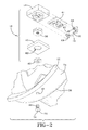
- the module 18 includes a casing or housing 34, an end cap 36, an insert body 38, a gasket 40, a circuit board 41, a sealing washer 42, and bolt 44.
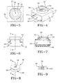
- the module housing 34 includes an internal pressure chamber 46 enclosed by three sidewalls 47 and end cap 36.
- An internal shoulder 48 is formed within the chamber 46 opposite an open side 58.
- a generally circular collar 52 projects from the housing 34 and an annular shoulder 50 projects into a collar passageway 56.
- the passageway 56 extends through the collar 52 and the annular shoulder 50 into communicating relationship with the chamber 46.
- a pair of circuit board supporting rail flanges 54 extend along the interior of the housing 34 as shown and a flat surface 57 is formed in a side of the collar defining bore 56.
- the housing 34 may be formed from any suitable material such moldable thermoplastic or thermoset plastics material having sufficient temperature and strength characteristics for strength and dimensional stability in a tire/wheel rim environment.
- the end cap 36 is a generally rectangular cap formed of suitable material such as the material of housing 34.
- the end cap is attached securely to the housing 34 by laser welding, ultrasonic welding, adhesive or other suitable means to enclose the opening 58 and includes a pair of integrally molded projecting protrusions 60 and a pair of protrusions 62.
- Protrusions 60, 62 locate the end cap 36 into the housing opening.
- the end cap 36 further has spaced apart pair of T-shaped protrusions 64.
- the circuit board 41 is inserted through the opening 58 and positioned on the support rail flanges 54. The board may then be slid into the chamber 46 of housing 34 until abutment.
- end cap 36 is securely attached by appropriate means to the housing 34 over the opening 58.
- Secure attachment of end cap 36 to the housing 34 creates an airtight seal between the end cap and the housing such that air within the chamber 46 cannot escape.
- Protrusions 64 engage the circuit board 41 within the chamber 46 to fix the board 41 in place and deter movement of the board within the housing 34.
- the insert body 38 is dimensioned and configured to seat within the housing opening 56 and includes a flat surface 66 that registers opposite the flat surface 57 of the housing collar 52. So positioned, the insert body 38 is constrained from rotating within the housing collar 52.
- the annular shoulder 50 of the collar 52 is positioned within an annular groove 68 in the insert body 38 and acts to locate and secure the insert body within the collar 52.
- the insert body 38 is formed having a threaded through bore 70.
- the body 38 may be formed of any suitable material having requisite strength.
- the insert body 38 is preferably although not necessary formed of stainless steel having internal threads to accept the mounting bolt 44.
- the bolt 44 is likewise preferably formed of metal.
- Washer 42 is preferably formed of a composite material. The metal to metal contact between the insert body 38, the washer 42, the bolt 44 and the rim 12 eliminates compression stress on the plastic housing 34.
- the mounting bolt 44 is externally threaded and includes a bolt head 72 and an axial through bore 74.
- the bolt may be approximately 6.35 mm ( ⁇ 1 ⁇ 4 inch) in length with 2.03 m ( ⁇ 0.08 inch) diameter through bore 74.
- FIGS. 14, 15, and 16 illustrate the gasket 40 in detail.
- the gasket 40 includes sidewalls 84 and having a wall 86.
- a larger dimensioned chamber 76 of circular cross-sectional configuration extends into the gasket wall 86 to an annular flange 78.
- a flat surface 80 defines a side of the chamber 76 within the gasket.
- An opening 82 of reduced diameter extends from the annular flange 78 to an opposite side of the gasket.
- the gasket is formed of a high temperature material such as a fluoro-elastomeric material.
- the washer 42 may likewise be formed of a high temperature material such as a composite metal and elastomeric material.
- the transponder board 41 may include temperature and pressure measuring devices common to the industry.
- the board 41 may include ID data storage and calibration constraints. Operation of the board 41 is to monitor and measure temperature and/or pressure within the tire 14 and communicate a signal representing measured values to an external reader (not shown). Devices suitable for use for such a purpose are common and commercially available.
- the tire pressure monitoring module 18 is mounted to the rim 12 as will be apparent from FIGS. 1 , 2 , and 3 .
- the circuit board 41 is sealed within the pressure chamber of the housing 34 by the end cap 36.
- the hole 28 is drilled through the rim surface 20 and the bolt 44 extends therethrough.
- the washer 42 receives the bolt shaft therethrough and abuts against surface 24 of the rim to prevent air from leaking from around the bolt.
- the housing collar portion 52 receives the insert body 38 therein with the annular flange 50 of the housing 34 entering into the annular groove 68 of the insert body.
- the gasket 40 is positioned over the housing 34 and receives the collar portion 52 of the housing 34 into the gasket opening 76.
- Flat surface 57 of the collar 52 registers opposite the flat surface 80 of the gasket 40 to prevent relative rotation from occurring between the gasket and the housing.
- the washer 42 is inserted into and seats within the gasket opening 82.
- the threaded shaft of bolt 44 extends through the washer 42 and the gasket 40 and threads into the insert body threaded bore 70.
- the tire pressure module 18 is thus firmly affixed to the rim surface 24 and against the rim surface 26.
- the bore 74 through the bolt 44 is in direct communication with the internal pressure chamber 46 of the housing 34 and the electronics on circuit board 41 for measuring temperature/pressure.
- the inflation pressure in the tire cavity 30 of the tire body 14 is transferred through the bore 74 of the bolt 44 to the pressure chamber in the module.
- the enclosed electronics within the chamber 46 sense the pressure and transmit an appropriate signal to an external reader.
- the subject tire pressure monitoring module 18 mounts directly to outer surface 24 of rim 12. The module is thus accessible for replacement or repair should the need arise. Moreover, the bolt head 72 is in direct contact with the tire cavity 30.
- the sensor module is mounted on the opposite side of the rim as the tires and does not contact either tire 14, 16.
- the pressure monitoring module 18 is accordingly in a non-contacting relationship with the tire(s) mounted to the rim 12. Accuracy of the module 18 in measuring air pressure within the tire(s) is accordingly not dependent on maintaining a secure mechanical coupling between the tire and the pressure sensor as is the case with state of the art systems such as valve stem mounted pressure monitoring systems.
- a plurality of grooves 88 are formed within the inner tire 16 and function to allow the air within the cavity 30 of tire 14 to have direct access to the bolt head 72.
- Inflation pressure may be measured without touching the tire(s) and a positive indication of specific tire pressure in the outer tire may be accurately read.
- the data transmission protocol within each module 18 may be designed to prevent one racing team from reading another team's tire/rim/module systems. Since the valve stem of the tires is not engaged by the subject invention module 18, a mechanical pressure gauge may be used on the valve stem if desired to validate the measurement of the module 18. Such a redundancy and cross-verification can insure that a correct determination of the tire pressure is made.
- the module 18 mounts on an outer surface of the rim 12 and is thus protected and can survive multiple races in contrast with tire mounted devices that must endure the forces imposed on the devices by the tire.
- the module 18 may be incorporated as a standard component of a tire/wheel assembly and the operation of the module may be verified before the tire/wheel assembly is released from production.
- the electronics within the module 18 may further work with or without electro-magnetic transmission shields. While only one sensor module 18 is shown attached to the rim, multiple modules 18 may be deployed if desired monitoring the same or differing cavities within the tire components.
Landscapes
- Engineering & Computer Science (AREA)
- Mechanical Engineering (AREA)
- Measuring Fluid Pressure (AREA)
Applications Claiming Priority (1)
| Application Number | Priority Date | Filing Date | Title |
|---|---|---|---|
| US11/641,333 US7478554B2 (en) | 2006-12-19 | 2006-12-19 | Rim mounted tire pressure monitoring system |
Publications (1)
| Publication Number | Publication Date |
|---|---|
| EP1935673A2 true EP1935673A2 (de) | 2008-06-25 |
Family
ID=39186804
Family Applications (1)
| Application Number | Title | Priority Date | Filing Date |
|---|---|---|---|
| EP07123314A Withdrawn EP1935673A2 (de) | 2006-12-19 | 2007-12-17 | Überwachungssystem für den Druck eines felgenmontierten Reifens |
Country Status (2)
| Country | Link |
|---|---|
| US (1) | US7478554B2 (de) |
| EP (1) | EP1935673A2 (de) |
Families Citing this family (23)
| Publication number | Priority date | Publication date | Assignee | Title |
|---|---|---|---|---|
| TWI327114B (en) * | 2006-01-30 | 2010-07-11 | Sanyo Electric Co | Pressure sensor installation method, tire and wheel installed with pressure sensor, and tire pressure sensing device |
| GB2446213B (en) * | 2007-01-31 | 2012-02-22 | Bf1Systems Ltd | A wheel sensor |
| WO2009006518A1 (en) | 2007-07-03 | 2009-01-08 | Continental Automotive Systems Us, Inc. | Universal tire pressure monitoring sensor |
| US7549330B2 (en) | 2007-09-14 | 2009-06-23 | The Goodyear Tire & Rubber Company | Leak down device for tire pressure monitoring system |
| US8742912B2 (en) * | 2008-12-31 | 2014-06-03 | Stmicroelectronics, Inc. | Self-powered sensor system for monitoring tire pressure |
| US20110041309A1 (en) * | 2009-08-24 | 2011-02-24 | Peter Ross Shepler | Method of installing tire electronics in a tire |
| US8561659B2 (en) * | 2009-08-24 | 2013-10-22 | The Goodyear Tire & Rubber Company | Tire and electronic device assembly |
| CN103874592B (zh) | 2011-08-09 | 2018-01-30 | 大陆汽车系统公司 | 用于激活轮胎压力监控器的定位过程的设备和方法 |
| US9676238B2 (en) | 2011-08-09 | 2017-06-13 | Continental Automotive Systems, Inc. | Tire pressure monitor system apparatus and method |
| CN103717416B (zh) | 2011-08-09 | 2019-02-22 | 大陆汽车系统公司 | 轮胎压力监控设备和方法 |
| US20130167485A1 (en) * | 2011-12-28 | 2013-07-04 | James V. Ireland | Tire pressure sensor storge unit and method |
| CN103692869A (zh) * | 2013-12-19 | 2014-04-02 | 伍宗仁 | 带延长气嘴并且具有充气功能的外置tpms传感器 |
| US9446636B2 (en) | 2014-02-26 | 2016-09-20 | Continental Automotive Systems, Inc. | Pressure check tool and method of operating the same |
| FR3019097B1 (fr) * | 2014-03-28 | 2018-07-06 | Continental Automotive France | Unite electronique de mesure de parametres de fonctionnement d'une roue de vehicule |
| US9533534B2 (en) | 2014-10-22 | 2017-01-03 | The Goodyear Tire & Rubber Company | Air maintenance tire and valve assembly and method |
| US9517664B2 (en) | 2015-02-20 | 2016-12-13 | Continental Automotive Systems, Inc. | RF transmission method and apparatus in a tire pressure monitoring system |
| DE102016213290A1 (de) | 2015-08-03 | 2017-02-09 | Continental Automotive Systems, Inc. | Vorrichtung, System und Verfahren zum Konfigurieren eines Reifeninformationssensors mit einem Übertragungsprotokoll auf der Basis von Fahrzeugtriggerkenngrößen |
| US9688108B1 (en) | 2015-12-03 | 2017-06-27 | The Goodyear Tire & Rubber Company | Dual tire air maintenance system and method |
| CN106585283B (zh) * | 2016-12-03 | 2017-12-29 | 东莞市皓奇企业管理服务有限公司 | 智能网络防爆胎装置 |
| US10703146B2 (en) | 2017-06-28 | 2020-07-07 | Sram, Llc | Pressure measuring device with alignment feature |
| US10919346B2 (en) * | 2017-06-28 | 2021-02-16 | Sram, Llc | Pressure measuring device for a wheel |
| US11273801B2 (en) | 2018-12-18 | 2022-03-15 | The Goodyear Tire & Rubber Company | Control system for an air maintenance tire system |
| EP4153436A4 (de) * | 2020-07-15 | 2024-10-16 | Sensata Technologies, Inc. | In kugel und hülse schwenkbarer tpm-sensor |
Family Cites Families (7)
| Publication number | Priority date | Publication date | Assignee | Title |
|---|---|---|---|---|
| US6446005B1 (en) * | 1999-08-13 | 2002-09-03 | Prolink, Inc. | Magnetic wheel sensor for vehicle navigation system |
| US7076999B1 (en) * | 2001-01-11 | 2006-07-18 | Lewis Lee Knox | Tire pressure monitoring system |
| US6769319B2 (en) * | 2001-07-09 | 2004-08-03 | Freescale Semiconductor, Inc. | Component having a filter |
| US6910372B2 (en) * | 2003-03-21 | 2005-06-28 | Bridgestone/Firestone North American Tire, Llc | Non-attached electronic monitoring device for tire |
| DE102005006904B4 (de) * | 2004-11-18 | 2014-10-30 | Volkswagen Ag | Reifendruckkontrollsystem für ein Fahrzeug |
| US7107830B1 (en) * | 2004-12-20 | 2006-09-19 | Mobiletron Electronics Co., Ltd. | Wireless tire pressure monitoring system (WTPMS) dual-sectional monitor signal transmission module |
| US7204136B2 (en) * | 2004-12-22 | 2007-04-17 | Tyco Electronics Corporation | Tire pressure sensor housing |
-
2006
- 2006-12-19 US US11/641,333 patent/US7478554B2/en not_active Expired - Fee Related
-
2007
- 2007-12-17 EP EP07123314A patent/EP1935673A2/de not_active Withdrawn
Also Published As
| Publication number | Publication date |
|---|---|
| US20080141766A1 (en) | 2008-06-19 |
| US7478554B2 (en) | 2009-01-20 |
Similar Documents
| Publication | Publication Date | Title |
|---|---|---|
| EP1935673A2 (de) | Überwachungssystem für den Druck eines felgenmontierten Reifens | |
| US7642904B2 (en) | Rim mounted pressure monitoring system for a tire with protected monitoring module | |
| US7549330B2 (en) | Leak down device for tire pressure monitoring system | |
| US7509849B2 (en) | Tire pressure gauge with data transmitter | |
| US7281421B2 (en) | Package for a tire pressure sensor assembly | |
| US7886589B2 (en) | Electronic unit for measuring operating parameters of a vehicle wheel | |
| US9016117B2 (en) | Tire monitoring apparatus, system and method of using the same | |
| WO1997025698A1 (en) | Wheelset monitoring system | |
| KR20000053619A (ko) | 대기압 측정 장치, 타이어 압력 측정치 수신기 및 압력측정치 보정 방법 | |
| WO2007084613A2 (en) | Tire pressure gauge with sensor support | |
| WO2004074017A1 (ja) | タイヤ用電子部品の取り付け構造 | |
| US6945104B2 (en) | Attachment mechanism for a tire monitoring system | |
| US7370522B2 (en) | Sensor system for tire | |
| US20220332153A1 (en) | Ball and socket articulating tpm sensor | |
| WO2013179019A1 (en) | A sensor | |
| JP3128136U (ja) | コンシールドタイプワイヤレスタイヤ空気圧センサー | |
| CN217347375U (zh) | 胎压传感器以及胎压检测系统 | |
| US20160146256A1 (en) | Instrumented bearing and method of manufacturing such an instrumented bearing | |
| US7242284B2 (en) | Tire condition detecting device, tire condition monitoring system, and method of attaching tire condition detecting device to tire wheel | |
| KR20210156770A (ko) | 압력 및 온도 측정 장치 | |
| TW202542009A (zh) | 胎壓偵測器其電子封蓋與殼體組合結構 | |
| CN210591249U (zh) | 一种角度可调的胎压监测装置 | |
| JPH0374210A (ja) | タイヤ装着用タイヤゲージ計測システム | |
| TW202542011A (zh) | 胎壓偵測器其氣嘴定位結構 | |
| KR20250052699A (ko) | 압력 센서 및 이를 포함하는 공조 장치 |
Legal Events
| Date | Code | Title | Description |
|---|---|---|---|
| PUAI | Public reference made under article 153(3) epc to a published international application that has entered the european phase |
Free format text: ORIGINAL CODE: 0009012 |
|
| AK | Designated contracting states |
Kind code of ref document: A2 Designated state(s): AT BE BG CH CY CZ DE DK EE ES FI FR GB GR HU IE IS IT LI LT LU LV MC MT NL PL PT RO SE SI SK TR |
|
| AX | Request for extension of the european patent |
Extension state: AL BA HR MK RS |
|
| STAA | Information on the status of an ep patent application or granted ep patent |
Free format text: STATUS: THE APPLICATION HAS BEEN WITHDRAWN |
|
| 18W | Application withdrawn |
Effective date: 20090417 |