EP1935764A2 - Dispositif de guidage d'air pour un véhicule automobile - Google Patents
Dispositif de guidage d'air pour un véhicule automobile Download PDFInfo
- Publication number
- EP1935764A2 EP1935764A2 EP07021093A EP07021093A EP1935764A2 EP 1935764 A2 EP1935764 A2 EP 1935764A2 EP 07021093 A EP07021093 A EP 07021093A EP 07021093 A EP07021093 A EP 07021093A EP 1935764 A2 EP1935764 A2 EP 1935764A2
- Authority
- EP
- European Patent Office
- Prior art keywords
- spoiler lip
- rest position
- air guiding
- guiding device
- spoiler
- Prior art date
- Legal status (The legal status is an assumption and is not a legal conclusion. Google has not performed a legal analysis and makes no representation as to the accuracy of the status listed.)
- Granted
Links
Images


Classifications
-
- B—PERFORMING OPERATIONS; TRANSPORTING
- B62—LAND VEHICLES FOR TRAVELLING OTHERWISE THAN ON RAILS
- B62D—MOTOR VEHICLES; TRAILERS
- B62D35/00—Vehicle bodies characterised by streamlining
- B62D35/005—Front spoilers
-
- Y—GENERAL TAGGING OF NEW TECHNOLOGICAL DEVELOPMENTS; GENERAL TAGGING OF CROSS-SECTIONAL TECHNOLOGIES SPANNING OVER SEVERAL SECTIONS OF THE IPC; TECHNICAL SUBJECTS COVERED BY FORMER USPC CROSS-REFERENCE ART COLLECTIONS [XRACs] AND DIGESTS
- Y02—TECHNOLOGIES OR APPLICATIONS FOR MITIGATION OR ADAPTATION AGAINST CLIMATE CHANGE
- Y02T—CLIMATE CHANGE MITIGATION TECHNOLOGIES RELATED TO TRANSPORTATION
- Y02T10/00—Road transport of goods or passengers
- Y02T10/80—Technologies aiming to reduce greenhouse gasses emissions common to all road transportation technologies
- Y02T10/82—Elements for improving aerodynamics
Definitions
- a generic air guide is from the DE 36 30 645 C2 known.
- This spoiler for a motor vehicle comprises a spoiler lip extending on the vehicle bend in the vehicle transverse direction, which can be moved via an actuating element from a retracted rest position into an extended operative position in which it builds up an aerodynamic effect.
- the actuator is designed as a flexible, inflatable tube that holds the spoiler lip in the operative position in its inflated state. If the hose is emptied or depressurized, it can fold up due to its flexible properties and the spoiler lip can be brought back into its rest position by means of a return device.
- the restoring device is formed by a spring which is fastened with its one end to the vehicle body and with its other end to the spoiler lip or on the actuating element.
- the spring When extending into the operative position, the spring is tensioned and after a pressure relief of the pneumatic actuator, the spring relaxes again and pulls the spoiler lip in its rest position. In the rest position, the spoiler lip is held by the spring, which thus also forms a retaining means for the spoiler lip in the rest position.
- a disadvantage of this spoiler is that the spoiler lip at least easily move or even swing in the rest position by the elastic design of the holding means, which on the one hand means that it develops a certain aerodynamic, but undesirable effect even in the rest position and it also A noise may occur when the spoiler lip vibrates while driving against the vehicle.
- the spring can be plastically deformed when the spoiler lip folds forward, which can take place, for example, if an obstacle is run over backwards. Such a deformed spring leads to a complete failure of this known louver.
- a similar embodiment of a louver is also from the DE 101 60 748 A1 according to which the flexible, inflatable actuating element is formed by a hose having at least one chamber.
- the restoring device is realized in this known spoiler lip in that in the elastically stretchable spoiler lip itself - when moving from the rest position to the extended operative position - restoring forces are built, which ensure at a pressure relief of the hose that the spoiler lip is moved back to the rest position ,
- a retaining means for the spoiler lip is formed by the fact that it rests in its rest position under pretension on the front end.
- the holding means elastic namely formed by the elastic spoiler lip itself, which may result in some cases similar problems as in the above-described louver.
- the spoiler lip can assume the rest position safely and is held almost motionless in the rest position, which is achieved with the couplable and decoupled with the spoiler lip rest position holder, which is executed inelastic.
- this home position holder could, for example, in the manner of a lock make a positive connection with the spoiler lip or hold the spoiler lip in the rest position due to a frictional connection. Shall the spoiler lip from the rest position are moved to the extended operative position, the rest position holder is decoupled from the spoiler lip and then activates the actuator.
- the rest position holder In the reverse direction of movement of the rest position holder is coupled to the spoiler lip again when the spoiler lip has assumed its rest position, in which it has been displaced by means of the restoring device.
- the rest position holder according to the invention therefore, the spoiler lip is held securely in the rest position regardless of the applied restoring forces by the restoring device, so that component and position tolerances remain without influence on the specifically predetermined rest position of the spoiler lip.
- due to the material for the spoiler lip caused aging and relaxation phenomena that can contribute to a change in the amount of restoring forces, thus exert essentially no influence on the rest position of the spoiler lip.
- the rest position holder ensures that in the retracted rest position the spoiler lip causes no or at least a constant aerodynamics for the motor vehicle, even if the motor vehicle is moved at different speeds, as long as the spoiler lip is held in the rest position.
- the rest position holder according to the invention is particularly preferably used in an air guiding device, in which the restoring device is itself formed by the spoiler lip which expands during the extension movement, that is, the restoring forces are built up in the spoiler lip.
- the rest position holder detects the spoiler lip during its retraction already shortly before its final rest position, ie in a partial position, and pulls it against the End stop, or the rest position holder is only coupled to the spoiler lip, when this has reached its final resting position.
- the rest position holder is designed as an at least magnetic or magnetizable holding element, which detects the spoiler lip with its magnetic effect and holds in the rest position, wherein the spoiler lip has at least one magnetic or magnetizable counter element.
- the spoiler lip already in the above-mentioned partial position and to pull completely into the rest position, preferably against the above-described end stop, the subject of claim 7.
- the magnetic effect deploying holding element in a simple way, the ability to couple the rest position holder with the spoiler lip in the rest position or the partial position and decouple for the extension movement of the spoiler lip again from this, as of the actuator only a larger Force as the magnetic holding force must be applied.
- the magnetic effect could also be switched on and off or activated and deactivated, as stated in claim 8.
- the holding element itself forms the end stop, which is particularly advantageous in the embodiment as a magnetic or magnetizable holding element.
- the holding element which can be coupled with the spoiler lip and decoupled from the spoiler lip, is attached to an actuating element and so can be moved from a retracted end position to an extended operating position and vice versa. This makes it possible to adjust the position of the rest position.
- the spoiler lip is movable by means of the holding element and the adjusting element in aerodynamically effective intermediate positions when the spoiler lip is coupled to the holding element. These intermediate positions are between the end position and the operating position of the holding element.
- the holding element acts with the actuating element as a further actuating element for the spoiler lip.
- the flexible, inflatable actuator is activated.
- the Fig. 1 shows a longitudinal section through a partially illustrated motor vehicle 1, a front end 2 with a designated also as a bumper fascia trim panel 3, behind which a bumper cross member, not shown here may be arranged.
- the bow-cladding part 3 has on its underside 4 a spoiler also designated as spoiler 5, which is present in a drawn with a solid line rest position RS and with its in the vehicle width direction (vehicle transverse direction) extending spoiler lip 6 adjacent to the bottom 4.
- the spoiler lip 6 extends downward in the direction of a roadway, not shown here.
- the louver 5 is equipped with a pneumatic actuator 7, which is designed as a flexible, inflatable tube 8 with at least one chamber 9 and 10 respectively.
- a pneumatic actuator 7 which is designed as a flexible, inflatable tube 8 with at least one chamber 9 and 10 respectively.
- Fig. 1 is the actuator 7 for the operative position WS of the spoiler lip 6 also to see in dash-dotted representation.
- the fact that the actuating element 7 is designed as a flexible, inflatable tube 8, it can be folded after its emptying or pressure relief, as it is in a solid line in Fig. 1 is shown. With its one end 11, the actuating element 7 is held, for example, on the underside 4 of the bow trim part 3.
- the spoiler lip 6 is made in a preferred embodiment of a stretchable and elastic material, such as an EPDM or the like. Adjacent to its free end 14, the spoiler lip 6 has a running in the vehicle transverse direction channel 15, in which a flexurally elastic rod 16 is inserted.
- the inner channel wall 17 of the channel 15 may in particular be formed by a guide means 18, which is designed, for example, as a metallic element, such as a flexible tube or a wire-like element with a wound wire following a helical line; Preferably, a spring steel wire is used.
- a guide means 18 which is designed, for example, as a metallic element, such as a flexible tube or a wire-like element with a wound wire following a helical line;
- a spring steel wire is used.
- the design of such a spoiler with a spoiler lip, a pneumatic actuator and a flexible elastic rod is from the above-mentioned DE 101 60 748 A1 known, and the DE 103 25 654 A1 describes for such a louver with a flexurally elastic rod a guide means for the flexurally elastic rod, so that it will not be discussed here.
- the spoiler lip 6 is made of an elastically stretchable material, it builds when transferring from the rest position RS in the extended operative position WS restoring forces RK, of which at least one force component, the spoiler lip 6 urges towards the underside 4 in pressure relief of the actuating element 7 again , that is moved to the rest position RS.
- the elastically stretchable spoiler lip 6 itself forms a restoring device in order to move the spoiler lip 6 from the operative position WS back into the rest position RS can.
- the spoiler lip 6 can already be biased in its rest position RS in accordance with their elastic elastic training such that it maintains the rest position RS biased. Consequently, the elastically prestressed spoiler lip 6 forms, in addition to the restoring device, a retaining means for the spoiler lip in the rest position RS.
- the louver 5 has a separate retaining means 19 which is inelastic relative to the retaining means inherent in the spoiler lip and acts as rest position holder 20, which holds the free end 14 of the spoiler lip 6 in the rest position RS, in which the rest position holder 20th is coupled with the spoiler lip 6 in the rest position RS.
- the spoiler lip 6 rests with its free end 14 on the rest position holder 20 so that it also forms an end stop 21 for the retraction movement of the spoiler lip 6.
- the actuating element 7 is inflated and the free end 14 of the spoiler lip 6 is decoupled from the home position holder 20.
- the spoiler lip 6 is again coupled to the rest position holder 20 when it has reached its rest position RS.
- the rest position holder 20 is executed in the embodiment shown as a fixedly attached to the bottom 4 magnetic or magnetizable holding member 22 and can be designed either as a permanent magnet or as a switched on and off electromagnet.
- the actuating element 7 during inflation for the extension movement of the spoiler lip 6 of the rest position RS in the active position WS develop a Ausstellkraft AK, which is greater than the (magnetic) holding force of the retaining element 22, whereby the spoiler lip 6 is decoupled with its free end 14 of the rest position holder 20 and can extend accordingly in the operative position WS.
- This embodiment would also be conceivable if the holding element 22 is designed as an electromagnet.
- the holding means 19 Due to the fact that the holding means 19 has or builds up a magnetic field, the spoiler lip can already be detected when depressing the actuating element 7 when retracting from the operative position WS to the rest position RS, if the spoiler lip 6 has not yet assumed its final rest position RS, ie the free end 14 is at a distance from the holding element 20.
- the holding means 22 additionally acts as a drive-in aid for the spoiler lip 6, if this is not completely brought into the rest position RS, for example due to a corresponding restoring force RK.
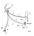
- Fig. 2 shows a second embodiment of the louver 5 with a holding means 19, wherein the rest position holder 20 is attached to an actuating element 24, which is designed here as a linear unit.
- the adjusting element 24 it is possible to shift the holding element 22 or the rest position switch 20 in an extended operating position BS, so that the spoiler lip 6 with its free end 14 already in the in Fig. 2 detected partial position TS detected and coupled to the holding element 22 and is taken by retraction of the holding member 22 in the rest position RS, in Fig. 3 you can see; In this case, the holding element 22 takes its retracted end position ES.
- the actuator 7 is not shown. Otherwise are in the Fig. 2 and 3 the same or equivalent components with the same reference numerals as in Fig. 1 Mistake.
- a further function of the actuating element 24 with the holding means 19 or rest position switch 20 or end stop 21 or holding element 22 is explained in more detail.
- the fact that the holding element 22 can be extended by means of the adjusting element 24 can, starting from the in Fig. 3 shown rest position RS the spoiler lip 6 are shifted to different, aerodynamically different acting intermediate positions ZS1, ZS2 and ZS3, depending on how far the holding element 22 between its retracted end position ES and its extended operating position BS is moved. All intermediate positions between the end position ES and the operating position BS are possible for the intermediate position ZS. This makes it possible to set different-acting intermediate positions ZS1, ZS2, ZS3 depending on the requirements of driving speed or other vehicle or chassis parameters.
- the actuating element 7 is correspondingly inflated and the spoiler lip 6 is decoupled with its free end 14 from the retaining element 22, so that the active position WS is approached from the respective intermediate position ZS can.
Landscapes
- Engineering & Computer Science (AREA)
- Chemical & Material Sciences (AREA)
- Combustion & Propulsion (AREA)
- Transportation (AREA)
- Mechanical Engineering (AREA)
- Superstructure Of Vehicle (AREA)
- Air Bags (AREA)
Applications Claiming Priority (1)
| Application Number | Priority Date | Filing Date | Title |
|---|---|---|---|
| DE102006060672A DE102006060672A1 (de) | 2006-12-21 | 2006-12-21 | Luftleiteinrichtung für ein Kraftfahrzeug |
Publications (3)
| Publication Number | Publication Date |
|---|---|
| EP1935764A2 true EP1935764A2 (fr) | 2008-06-25 |
| EP1935764A3 EP1935764A3 (fr) | 2008-08-06 |
| EP1935764B1 EP1935764B1 (fr) | 2011-04-27 |
Family
ID=39321431
Family Applications (1)
| Application Number | Title | Priority Date | Filing Date |
|---|---|---|---|
| EP07021093A Active EP1935764B1 (fr) | 2006-12-21 | 2007-10-29 | Dispositif de guidage d'air pour un véhicule automobile |
Country Status (2)
| Country | Link |
|---|---|
| EP (1) | EP1935764B1 (fr) |
| DE (2) | DE102006060672A1 (fr) |
Cited By (6)
| Publication number | Priority date | Publication date | Assignee | Title |
|---|---|---|---|---|
| GB2491024A (en) * | 2011-05-16 | 2012-11-21 | Porsche Ag | Front spoiler for motor vehicle |
| CN102975779A (zh) * | 2011-08-30 | 2013-03-20 | F·波尔希名誉工学博士公司 | 用于机动车辆的空气导向装置 |
| JP2014084104A (ja) * | 2012-10-23 | 2014-05-12 | Dr Ing Hcf Porsche Ag | 自動車用の空気案内装置 |
| US8864215B2 (en) | 2011-09-07 | 2014-10-21 | Dr. Ing. H. C. F. Porsche Aktiengesellschaft | Air guiding device for a motor vehicle |
| EP3401194A1 (fr) * | 2017-05-04 | 2018-11-14 | Alpha Team GmbH | Ensemble de surfaces de guidage d'air et véhicule automobile pourvu d'un tel dispositif surfaces de guidage d'air |
| WO2022106477A1 (fr) * | 2020-11-18 | 2022-05-27 | Bayerische Motoren Werke Aktiengesellschaft | Élément de guidage d'air et véhicule comportant au moins un élément de guidage d'air |
Families Citing this family (6)
| Publication number | Priority date | Publication date | Assignee | Title |
|---|---|---|---|---|
| DE102008059692A1 (de) * | 2008-11-29 | 2010-06-02 | Daimler Ag | Pneumatische Frontspoilervorrichtung |
| US8292350B2 (en) | 2010-04-26 | 2012-10-23 | GM Global Technology Operations LLC | Inflatable vehicle air dam with bidirectional deploy/stow system |
| DE102012020738B4 (de) | 2012-10-23 | 2022-06-02 | Apollo Vredestein B.V. | Luftleiteinrichtung eines Kraftfahrzeugs |
| DE102014104156A1 (de) | 2014-03-26 | 2015-10-01 | Dr. Ing. H.C. F. Porsche Aktiengesellschaft | Luftleiteinrichtung für ein Kraftfahrzeug |
| DE102019112924B4 (de) * | 2019-05-16 | 2022-05-05 | Dr. Ing. H.C. F. Porsche Aktiengesellschaft | Frontspoiler |
| DE102021004418A1 (de) | 2021-08-31 | 2022-01-13 | Daimler Ag | Luftleiteinrichtung für ein Schiebedach eines Kraftwagens |
Family Cites Families (5)
| Publication number | Priority date | Publication date | Assignee | Title |
|---|---|---|---|---|
| DE7906193U1 (de) * | 1978-03-24 | 1979-05-31 | Ford-Werke Ag, 5000 Koeln | Kraftfahrzeug-karosserie |
| FR2540813B1 (fr) * | 1983-02-10 | 1988-01-22 | Equip Publicitaires Ste Nl | Perfectionnements aux deflecteurs du type " spoiler " pour vehicules automobiles |
| DE3630645A1 (de) * | 1986-09-09 | 1988-03-10 | Daimler Benz Ag | Frontverkleidung fuer fahrzeuge, insbesondere personenkraftwagen |
| DE19824467A1 (de) * | 1998-05-30 | 1999-12-02 | Volkswagen Ag | Ablagefach in einem Fahrzeug |
| DE10160748B8 (de) * | 2001-12-11 | 2005-09-29 | Dr.Ing.H.C. F. Porsche Ag | Kraftfahrzeug mit einer eine Luftleiteinrichtung umfassenden Frontpartie |
-
2006
- 2006-12-21 DE DE102006060672A patent/DE102006060672A1/de not_active Withdrawn
-
2007
- 2007-10-29 EP EP07021093A patent/EP1935764B1/fr active Active
- 2007-10-29 DE DE502007007049T patent/DE502007007049D1/de active Active
Cited By (10)
| Publication number | Priority date | Publication date | Assignee | Title |
|---|---|---|---|---|
| GB2491024A (en) * | 2011-05-16 | 2012-11-21 | Porsche Ag | Front spoiler for motor vehicle |
| GB2491024B (en) * | 2011-05-16 | 2013-04-10 | Porsche Ag | Front spoiler for a motor vehicle |
| CN102975779A (zh) * | 2011-08-30 | 2013-03-20 | F·波尔希名誉工学博士公司 | 用于机动车辆的空气导向装置 |
| US8562067B2 (en) | 2011-08-30 | 2013-10-22 | Dr. Ing. H.C. F. Porsche Aktiengesellschaft | Air guiding device for a motor vehicle |
| CN102975779B (zh) * | 2011-08-30 | 2016-12-21 | F·波尔希名誉工学博士公司 | 用于机动车辆的空气导向装置 |
| US8864215B2 (en) | 2011-09-07 | 2014-10-21 | Dr. Ing. H. C. F. Porsche Aktiengesellschaft | Air guiding device for a motor vehicle |
| JP2014084104A (ja) * | 2012-10-23 | 2014-05-12 | Dr Ing Hcf Porsche Ag | 自動車用の空気案内装置 |
| EP3401194A1 (fr) * | 2017-05-04 | 2018-11-14 | Alpha Team GmbH | Ensemble de surfaces de guidage d'air et véhicule automobile pourvu d'un tel dispositif surfaces de guidage d'air |
| WO2022106477A1 (fr) * | 2020-11-18 | 2022-05-27 | Bayerische Motoren Werke Aktiengesellschaft | Élément de guidage d'air et véhicule comportant au moins un élément de guidage d'air |
| US12522305B2 (en) | 2020-11-18 | 2026-01-13 | Bayerische Motoren Werke Aktiengesellschaft | Air-guiding element and vehicle having at least one air-guiding element |
Also Published As
| Publication number | Publication date |
|---|---|
| DE102006060672A1 (de) | 2008-06-26 |
| EP1935764B1 (fr) | 2011-04-27 |
| DE502007007049D1 (de) | 2011-06-09 |
| EP1935764A3 (fr) | 2008-08-06 |
Similar Documents
| Publication | Publication Date | Title |
|---|---|---|
| EP1935764B1 (fr) | Dispositif de guidage d'air pour un véhicule automobile | |
| DE102008024892B4 (de) | Luftleiteinrichtung | |
| EP3825497B1 (fr) | Serrure de véhicule automobile | |
| EP3687844B1 (fr) | Systeme de store pour toit de vehicule | |
| DE10200553C1 (de) | Luftfeder mit integriertem Steuerventil | |
| DE102008039972A1 (de) | Frontstruktur eines Kraftfahrzeugs | |
| EP2928712B1 (fr) | Dispositif de protection, en particulier dispositif de protection contre le soleil pour l'habitacle d'un véhicule automobile | |
| DE102017208885B4 (de) | Luftleitvorrichtung für ein Kraftfahrzeug, Kraftfahrzeug | |
| DE102011085933B4 (de) | Unterbodenverkleidung für ein Kraftfahrzeug mit beweglichen Teilen | |
| DE102011015009A1 (de) | Strömungsleitvorrichtung für ein Fahrzeug | |
| DE102019110084A1 (de) | Windabweiser für eine Scheibenwischanlage eines Kraftwagens | |
| DE102013017456A1 (de) | Verstellvorrichtung für eine Frontklappe und zugehöriges Kraftfahrzeug | |
| EP1897723B1 (fr) | Capote de cabriolet | |
| WO2000003897A1 (fr) | Module de retenue pour un vehicule a moteur | |
| DE102005001548A1 (de) | Vorrichtung zum Betätigen eines Verriegelungsmechanismus | |
| DE102015200359B4 (de) | Stoßfängersystem für ein Fahrzeug und Fahrzeug | |
| DE602004004004T2 (de) | Teleskopische Scheinwerfer-Reinigungseinrichtung für ein Kraftfahrzeug | |
| DE102008024895B4 (de) | Luftleiteinrichtung | |
| DE102005027450B4 (de) | Windabweiser für ein Schiebedach | |
| DE102008037244A1 (de) | Stoßfängeranordnung für ein Kraftfahrzeug | |
| DE102007051464B3 (de) | Versteifungselement für die Fahrzeugkarosserie | |
| DE102019104504A1 (de) | Kraftfahrzeug | |
| DE102004059737A1 (de) | Kraftfahrzeug | |
| DE102007060483B4 (de) | Fahrzeugdachvorrichtung | |
| DE102007036403A1 (de) | Spoilereinrichtung |
Legal Events
| Date | Code | Title | Description |
|---|---|---|---|
| PUAI | Public reference made under article 153(3) epc to a published international application that has entered the european phase |
Free format text: ORIGINAL CODE: 0009012 |
|
| AK | Designated contracting states |
Kind code of ref document: A2 Designated state(s): AT BE BG CH CY CZ DE DK EE ES FI FR GB GR HU IE IS IT LI LT LU LV MC MT NL PL PT RO SE SI SK TR |
|
| AX | Request for extension of the european patent |
Extension state: AL BA HR MK RS |
|
| PUAL | Search report despatched |
Free format text: ORIGINAL CODE: 0009013 |
|
| RAP1 | Party data changed (applicant data changed or rights of an application transferred) |
Owner name: DR. ING. H.C. F. PORSCHE AKTIENGESELLSCHAFT |
|
| AK | Designated contracting states |
Kind code of ref document: A3 Designated state(s): AT BE BG CH CY CZ DE DK EE ES FI FR GB GR HU IE IS IT LI LT LU LV MC MT NL PL PT RO SE SI SK TR |
|
| AX | Request for extension of the european patent |
Extension state: AL BA HR MK RS |
|
| 17P | Request for examination filed |
Effective date: 20090206 |
|
| 17Q | First examination report despatched |
Effective date: 20090313 |
|
| AKX | Designation fees paid |
Designated state(s): DE FR GB IT |
|
| RAP1 | Party data changed (applicant data changed or rights of an application transferred) |
Owner name: DR. ING. H.C. F. PORSCHE AG |
|
| GRAP | Despatch of communication of intention to grant a patent |
Free format text: ORIGINAL CODE: EPIDOSNIGR1 |
|
| GRAC | Information related to communication of intention to grant a patent modified |
Free format text: ORIGINAL CODE: EPIDOSCIGR1 |
|
| GRAS | Grant fee paid |
Free format text: ORIGINAL CODE: EPIDOSNIGR3 |
|
| GRAA | (expected) grant |
Free format text: ORIGINAL CODE: 0009210 |
|
| AK | Designated contracting states |
Kind code of ref document: B1 Designated state(s): DE FR GB IT |
|
| REG | Reference to a national code |
Ref country code: GB Ref legal event code: FG4D Free format text: NOT ENGLISH |
|
| REF | Corresponds to: |
Ref document number: 502007007049 Country of ref document: DE Date of ref document: 20110609 Kind code of ref document: P |
|
| REG | Reference to a national code |
Ref country code: DE Ref legal event code: R096 Ref document number: 502007007049 Country of ref document: DE Effective date: 20110609 |
|
| PLBE | No opposition filed within time limit |
Free format text: ORIGINAL CODE: 0009261 |
|
| STAA | Information on the status of an ep patent application or granted ep patent |
Free format text: STATUS: NO OPPOSITION FILED WITHIN TIME LIMIT |
|
| 26N | No opposition filed |
Effective date: 20120130 |
|
| REG | Reference to a national code |
Ref country code: DE Ref legal event code: R097 Ref document number: 502007007049 Country of ref document: DE Effective date: 20120130 |
|
| REG | Reference to a national code |
Ref country code: FR Ref legal event code: PLFP Year of fee payment: 9 |
|
| REG | Reference to a national code |
Ref country code: FR Ref legal event code: PLFP Year of fee payment: 10 |
|
| REG | Reference to a national code |
Ref country code: FR Ref legal event code: PLFP Year of fee payment: 11 |
|
| REG | Reference to a national code |
Ref country code: FR Ref legal event code: PLFP Year of fee payment: 12 |
|
| PGFP | Annual fee paid to national office [announced via postgrant information from national office to epo] |
Ref country code: FR Payment date: 20181022 Year of fee payment: 12 Ref country code: IT Payment date: 20181024 Year of fee payment: 12 Ref country code: GB Payment date: 20181019 Year of fee payment: 12 |
|
| GBPC | Gb: european patent ceased through non-payment of renewal fee |
Effective date: 20191029 |
|
| PG25 | Lapsed in a contracting state [announced via postgrant information from national office to epo] |
Ref country code: IT Free format text: LAPSE BECAUSE OF NON-PAYMENT OF DUE FEES Effective date: 20191029 Ref country code: GB Free format text: LAPSE BECAUSE OF NON-PAYMENT OF DUE FEES Effective date: 20191029 Ref country code: FR Free format text: LAPSE BECAUSE OF NON-PAYMENT OF DUE FEES Effective date: 20191031 |
|
| P01 | Opt-out of the competence of the unified patent court (upc) registered |
Effective date: 20230526 |
|
| PGFP | Annual fee paid to national office [announced via postgrant information from national office to epo] |
Ref country code: DE Payment date: 20251029 Year of fee payment: 19 |