EP1935780A2 - Appareil de sortie - Google Patents
Appareil de sortie Download PDFInfo
- Publication number
- EP1935780A2 EP1935780A2 EP07023815A EP07023815A EP1935780A2 EP 1935780 A2 EP1935780 A2 EP 1935780A2 EP 07023815 A EP07023815 A EP 07023815A EP 07023815 A EP07023815 A EP 07023815A EP 1935780 A2 EP1935780 A2 EP 1935780A2
- Authority
- EP
- European Patent Office
- Prior art keywords
- shaft
- ausfahrgerät
- extension part
- sliding
- extension
- Prior art date
- Legal status (The legal status is an assumption and is not a legal conclusion. Google has not performed a legal analysis and makes no representation as to the accuracy of the status listed.)
- Withdrawn
Links
- 238000009434 installation Methods 0.000 claims description 3
- 230000001747 exhibiting effect Effects 0.000 claims 1
- 238000010276 construction Methods 0.000 description 9
- 238000004519 manufacturing process Methods 0.000 description 8
- 230000035939 shock Effects 0.000 description 8
- 238000005452 bending Methods 0.000 description 3
- 230000006835 compression Effects 0.000 description 3
- 238000007906 compression Methods 0.000 description 3
- 229920001875 Ebonite Polymers 0.000 description 2
- 230000005540 biological transmission Effects 0.000 description 2
- 238000013016 damping Methods 0.000 description 2
- 238000005516 engineering process Methods 0.000 description 2
- XLYOFNOQVPJJNP-UHFFFAOYSA-N water Substances O XLYOFNOQVPJJNP-UHFFFAOYSA-N 0.000 description 2
- 230000004913 activation Effects 0.000 description 1
- 230000002411 adverse Effects 0.000 description 1
- 230000015572 biosynthetic process Effects 0.000 description 1
- 230000009849 deactivation Effects 0.000 description 1
- 238000005553 drilling Methods 0.000 description 1
- 230000000694 effects Effects 0.000 description 1
- 229920001971 elastomer Polymers 0.000 description 1
- 239000000806 elastomer Substances 0.000 description 1
- 239000000463 material Substances 0.000 description 1
- 230000003287 optical effect Effects 0.000 description 1
- 239000013307 optical fiber Substances 0.000 description 1
- 239000013535 sea water Substances 0.000 description 1
- 239000000725 suspension Substances 0.000 description 1
Images


Classifications
-
- B—PERFORMING OPERATIONS; TRANSPORTING
- B63—SHIPS OR OTHER WATERBORNE VESSELS; RELATED EQUIPMENT
- B63G—OFFENSIVE OR DEFENSIVE ARRANGEMENTS ON VESSELS; MINE-LAYING; MINE-SWEEPING; SUBMARINES; AIRCRAFT CARRIERS
- B63G8/00—Underwater vessels, e.g. submarines; Equipment specially adapted therefor
- B63G8/38—Arrangement of visual or electronic watch equipment, e.g. of periscopes, of radar
-
- F—MECHANICAL ENGINEERING; LIGHTING; HEATING; WEAPONS; BLASTING
- F16—ENGINEERING ELEMENTS AND UNITS; GENERAL MEASURES FOR PRODUCING AND MAINTAINING EFFECTIVE FUNCTIONING OF MACHINES OR INSTALLATIONS; THERMAL INSULATION IN GENERAL
- F16C—SHAFTS; FLEXIBLE SHAFTS; ELEMENTS OR CRANKSHAFT MECHANISMS; ROTARY BODIES OTHER THAN GEARING ELEMENTS; BEARINGS
- F16C29/00—Bearings for parts moving only linearly
- F16C29/12—Arrangements for adjusting play
- F16C29/123—Arrangements for adjusting play using elastic means
-
- F—MECHANICAL ENGINEERING; LIGHTING; HEATING; WEAPONS; BLASTING
- F16—ENGINEERING ELEMENTS AND UNITS; GENERAL MEASURES FOR PRODUCING AND MAINTAINING EFFECTIVE FUNCTIONING OF MACHINES OR INSTALLATIONS; THERMAL INSULATION IN GENERAL
- F16C—SHAFTS; FLEXIBLE SHAFTS; ELEMENTS OR CRANKSHAFT MECHANISMS; ROTARY BODIES OTHER THAN GEARING ELEMENTS; BEARINGS
- F16C2326/00—Articles relating to transporting
- F16C2326/30—Ships, e.g. propelling shafts and bearings therefor
Definitions
- the invention relates to a Ausfahr réelle, in particular for a submarine with the features specified in the preamble of claim 1.
- a Ausfahrtechnikn In submarines, it is state of the art, especially in the tower area to arrange a variety of Ausfahrtechnikn that are provided for different tasks and serve that can be spent out of submerged state of the boat components over water, for example, a periscope to optical explorations or to be able to communicate via radio or to determine the location by means of GPS.
- numerous other applications such as radar, weapons and the like are known, which are arranged on Ausfahrtechnikn.
- Known Ausfahrtechnik consist of a storage rack, which is anchored fundamentally on the pressure hull of the submarine and having a shaft in which an extension is arranged telescopically. Sliding bearings are provided between the shaft and the extension part, which ensure safe guidance and storage of the extension part in the shaft.
- a secure and precise storage and leadership is achieved in that a circular cross-section and tubular shaft is used, in which the extension part is arranged with a piston-like sliding and guide member, between these components rotating bearings are arranged, which the forces of Extension part transferred to the shaft and vice versa.
- the present invention seeks to provide a generic Ausfahrêt so that it is on the one hand as easy as possible, space and weight saving and on the other hand manufacturing technology can be made as simple as possible, but can absorb high lateral forces.
- the Ausfahrfind invention is designed especially for a submarine for military use and has a stationary storage rack with at least one prismatic in cross-section shaft in which an extension is arranged telescopically. Sliding bearings are provided between the shaft and the extension part. According to the invention, at least one bearing is resiliently biased in a direction substantially transversely to the direction of travel of the extension part.
- the extension device according to the invention has a bearing between the extension part and the shaft, which is elastic due to the spring effect, ie can absorb forces in the direction transverse to the travel direction, without the bearing as such being adversely affected thereby.
- the forces are at least partially absorbed by the spring force in the camp. Due to the bias large forces can be absorbed with a small spring travel. In addition, this always ensures the safe investment of the bearing parts together.
- each spring also has a certain damping property
- the storage according to the invention is particularly advantageous in terms of shock loading.
- a plurality of such spring-biased sliding bearings are expediently provided distributed over the circumference, which guide the extension part within the shaft safely and support. Another significant advantage of this training is in the manufacturing simplification.
- Linear plain bearings as they are known in generic Ausfahrtechnikn, each consist of a typically shaft side arranged slideway and a back and forth sliding, ausfahrteil 7 arranged slider. According to the invention, it is particularly advantageous and easy to manufacture, to mount the slider resiliently and form the slideway firmly and rigidly on the shaft, however, a reverse arrangement is also conceivable.
- the slideways are formed by profiles, preferably open or closed hollow profiles, which are fastened on the shaft side.
- Such hollow profiles give the shaft on the one hand additional stability, can form multiple slideways and are also inexpensive to manufacture.
- suitable profiles the remaining shaft construction can be designed comparatively easily, which in turn leads to material and weight savings.
- the profiles are arranged in the corners of the shaft, since they most effectively reinforce the shaft and then can absorb large forces in conjunction with the shaft.
- profiles hollow sections typically profiles prismatic cross-section, z.
- Rectangular profiles used which abut with rectangular cross-section shaft formation with two sides of the shaft and two mutually offset by 90 ° to form slideways.
- deviating cross section prismatic hollow profiles may also be advantageously used, wherein the angle between the sliding surfaces of a hollow profile should preferably span between 60 ° and 120 ° in order to be able to transmit compressive forces from these directions.
- an inventive sliding body is connected via a rubber-like elastomer element with the extension part or is formed entirely or partially from an elastomeric element.
- the elastomeric elements of opposing bearings are designed and arranged so that they are biased in the installed position, so always ensure a certain contact pressure between the slider and slideway. Rubbery elastomeric elements are inexpensive, can absorb high forces, have good damping properties and are also seawater resistant.
- a sliding body can also be mounted movably on the extension part in the direction transverse to the travel direction, wherein a pretensioned spring element between the extension part and the sliding body is then arranged in the installed position.
- This spring element may for example be a helical compression spring or a plate spring package or a rubber-elastic spring element.
- the slider is movable not only against spring force transversely to the direction of travel, but also limited pivotally mounted on the extension part, so that the slider regardless of the position between the extension and shaft always applies the entire surface of the slide, whereby unacceptably high surface pressures are avoided in the camp.
- the extension part advantageously has a sliding and guide part, which takes over the sliding and guiding function of the entire extension part and which advantageously carries the sliding body in two planes spaced apart in the extension direction in order to be able to transmit moments from the extension part to the shaft and vice versa to a sufficient extent
- the sliding and guide part is suitably adapted to the cross-sectional shape of the shaft with respect to its outer contour, whereas the rest of the extension part expediently identifies a rounded, flow-adapted form, as is known per se in Ausfahrtechnikn.
- the lifting cylinder or cylinders which are provided for extending and retracting the extension part from the shaft can be arranged next to the shaft in a manner known per se.
- the lifting cylinder or cylinders which are provided for extending and retracting the extension part from the shaft can be arranged next to the shaft in a manner known per se.
- it is particularly advantageous what with the use of a prismatic in cross-section shaft readily it is possible to arrange the lifting cylinder within the shaft. This results in a very space-saving compact solution, which is particularly advantageous if a plurality of Ausfahrtechnikn is to be arranged side by side.
- an energy chain is provided between the boat-fixed storage rack with the shaft and the Ausfahrteil, which advantageously leads all supply and data lines between the storage rack and Ausfahrteil and protects against too tight bending radii.
- Such an energy chain can advantageously be arranged standing inside the shaft or also hanging next to the shaft.
- the storage according to the invention is, as mentioned above, in particular also with regard to shock resistance of the Ausfahrschuls advantage.
- one or more other positive locking means which secure the Ausfahrteil in the transverse direction to the shaft form-fitting manner.
- Such form-locking means can be structurally simple and ensure that all forces are transmitted transversely to the extension direction between extension and shaft or the foundation of the Ausfahrtechniks when retracted Ausfahr réelle.
- a pin-like, upwardly directed projection may be provided, which engages in a recess provided for this purpose on the underside of the extension part recess.
- a pin-like projection is also arranged on the underside of the extension part, which in turn engages in an aligned recess at the top of the shaft bottom.
- the storage rack of the Ausfahr réelles can be relatively easily built, according to a development of the invention provides to extend the lower ends of the shaft typically supporting in its corners and slideways forming profiles down beyond the storage rack out and there form-fitting set in the pressure body to in this way, in particular to be able to initiate the high lateral forces occurring under shock loading bypassing the storage rack as directly as possible in the pressure body.
- this is advantageously achieved in that the profiles formed closed towards the bottom and there are provided with a threaded pin, which passes through a recess in the bottom plate of the storage rack and back is bolted thereto via a nut to the storage rack. With its outer circumference, this nut sits snugly in a blind hole drilled in the outer wall of the pressure hull.
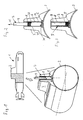
- FIG. 1 illustrated submarine 1 has a cylindrical pressure body 2, on which in the region of the tower structure 3 here an example Ausfahr réelle 4 is shown.
- the Ausfahr réelle 4 has a storage rack 5, which is fixedly connected to the pressure body 2 and the foundation of the Ausfahr advocatess 4 forms.
- the storage rack and foundation 5 carries a from the pressure hull 2 in normal driving position vertically upwardly directed shaft 6, in the interior of an extension 7 is arranged telescopically.
- the extension part 7 has a sliding and guide part 8, with which it is mounted and guided within the shaft 6.
- the extending over the sliding and guide part 8 part 9 of the extension part 7 forms the part that can be moved out of the shaft 6 and the free end penetrates the water surface while the boat remains submerged.
- the storage of the extension part 7, in particular of the sliding and guide part 8 within the shaft 6 is based on the FIGS. 4 to 6 shown in detail.
- the in cross-section ( Fig. 5 ) rectangular shaft 6 is formed as a welded construction and has in its four corners Rectangular hollow sections 10, which have a square cross-section, reinforce the shaft 6 and each form two along the shaft 6 extending, offset by 90 ° to each other arranged slideways 11 as storage areas.
- Each slide 11 forms part of a sliding bearing whose other part is formed by a sliding body 12 which is fixed to the sliding and guide part 8.
- Each slider 12 is connected via a spring element 13, which in the basis of the FIGS. 4 to 6 illustrated embodiment consists of hard rubber, connected to the sliding and guide part 8.
- the arrangement of the sliding body 12 with the spring elements 13 on the sliding and guide part 8 is selected so that all sixteen sliding body 12 rest against the associated, opposing slideways 11 without play. In this case, the spring elements 13 are biased, so that a system of sliding body 12 is ensured even when lateral forces on the shaft 6 or in particular the part 9 of the extension 7 act.
- the biased spring elements 13 not only provide for a system of sliding body 12 on the slideways 11 in the case of load, but also serve to compensate for manufacturing tolerances, as shown by Fig. 6 is shown in extreme form for illustrative purposes.
- the rectangular hollow profile 10 is not aligned exactly parallel to the wall of the shaft 6, so that there is an angular offset, which is compensated by the two spring elements 13 shown there readily, so that the sliding body 12 over the entire surface of the slideways 11.
- the basis of Fig. 6 shown angular offset represents only one of the possible tolerances.
- the distance between opposing slideways 11 change over the length, or the slideways 11 may have errors in their parallelism or their plane surface itself. All these errors are compensated within limits by the prestressed spring elements 13.
- the sliding and guiding part 8 the shape of which Fig. 5 shows, substantially corresponding to the inner contour of the shaft 6, has recesses 14 of the otherwise rectangular cross-section at all four corners corresponding to the rectangular hollow sections 10 arranged therein in the shaft 6.
- the free space formed thereby is filled by the rectangular hollow profiles 10 and the sliding body 12 and spring elements 13 arranged therebetween.
- the sliding and guide part 8 is formed as a closed hollow body and optionally opened at the bottom.
- In the extension direction 15 is followed up to the sliding and guide part 8 of the flow-rounded in cross-section formed part 9, which can be moved out of the tower structure 3, as shown by Fig. 2 is shown.
- a total of two times eight bearings are provided, in spaced apart in the extension direction 15 levels 16 and 17th
- All sixteen bearings of the sliding and guide member 8 are formed as a thrust bearing and are based on the total of eight slideways 11, which extend substantially over the entire length of the shaft 6.
- the spring elements 13 between the sliding bodies 12 and a corresponding support body on the sliding and guide part 8 are shown.
- these components can also be formed by a single, for example consisting of hard rubber sliding and spring element or by way of example, as is clear from the FIGS. 7 to 10 is shown.
- a bearing bracket 18 which is annular and formed with a spherical inner contour.
- This bearing bracket 18 is divided into two for assembly purposes and includes a correspondingly spherically shaped inner part 19, in which a slider 20 is guided transversely to the sliding surface 21 slidably.
- the slider 20 on its side facing away from the sliding surface 21 a pin 22 which engages in a corresponding recess of the bearing bracket 18 at a distance and extends into a stepped bore 23 of the inner part 19, arranged in the sacklochierim interior a helical compression spring 24 spring biased is the force applied to the pin 22 in the direction of the sliding surface 21.
- the sliding surface 21 is, as in particular in Fig.
- a known energy chain 25 is used. This is a hollow chain, whose interior, which is typically open on one side, receives and protects all data and supply lines, for example hydraulic, electrical and optical fiber lines for energy and data transmission.
- the chain links of this energy chain 25 are mounted movable so that the bending radius of the chain is limited and thus protects the lines lying therein against unduly tight bending.
- the energy chain 25 is arranged vertically, ie it is struck laterally in the shaft 6 in the lower region, extends along the shaft wall upwards, on the sliding and guide part 8 laterally past and is fixed there from above on the sliding and guide part 8.
- a corresponding free space for the energy chain 25 must be provided between the part 9 of the extension part 7 and the shaft 6, whereas in the embodiment according to the FIGS. 11 and 12 can be dispensed with such a free space, instead a shaft section 26 is provided, but which can be designed largely open.
- the drive of the extension part 7 by means of a hydraulic lifting cylinder 32, which is supported on the bottom of the shaft 6 on the one hand and with the free end of its piston rod 33 on part 9 of the extension part 7.
- an additional positive connection between the sliding and guide part 8 and the bearing frame and foundation 5 is provided, which is provided in particular for receiving forces transversely to the extension direction 15.
- a pin-like projection 28 is provided on the underside of each slide and guide member 8 and aligned in the foundation 5 a recess 29.
- an upwardly directed pin-like projection 30 is provided on the foundation 5 and in the extension direction 15 in alignment Underside of the sliding and guide member 8 a corresponding recess 31.
- each rectangular hollow profile 10 is clamped to the foundation plate 35.
- Each nut 36 has a cylindrical outer periphery which is interrupted only by recesses 37, via which a tool for tightening the respective nut 36 can engage.
- each nut 36 is seated in a correspondingly accurately formed blind hole 38 which is provided in the outside of the pressure body 2.
- a correspondingly accurately formed blind hole 38 which is provided in the outside of the pressure body 2.
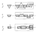
- FIGS. 4 and 5 illustrated Ausfahrterrorism having a rectangular cross-section shaft 6 can be arranged with several such Ausfahrtechnik with rectangular shaft of different sizes immediately next to each other, as shown by Fig. 15 is shown schematically.
- Fig. 15 shows schematically.
- Fig. 16 shows the juxtaposition of Ausfahrtechnikn with cross-sectionally triangular shafts of different sizes.
- the arrangement of the slideways is then selected accordingly, and instead of the rectangular hollow sections, if necessary, also open hollow profiles or flat profiles are used, as this is structurally the cheapest.
Landscapes
- Engineering & Computer Science (AREA)
- General Engineering & Computer Science (AREA)
- Mechanical Engineering (AREA)
- Radar, Positioning & Navigation (AREA)
- Aviation & Aerospace Engineering (AREA)
- Bearings For Parts Moving Linearly (AREA)
- Warehouses Or Storage Devices (AREA)
- Sliding-Contact Bearings (AREA)
Applications Claiming Priority (1)
| Application Number | Priority Date | Filing Date | Title |
|---|---|---|---|
| DE102006061294A DE102006061294B3 (de) | 2006-12-22 | 2006-12-22 | Ausfahrgerät |
Publications (2)
| Publication Number | Publication Date |
|---|---|
| EP1935780A2 true EP1935780A2 (fr) | 2008-06-25 |
| EP1935780A3 EP1935780A3 (fr) | 2017-04-05 |
Family
ID=39244655
Family Applications (1)
| Application Number | Title | Priority Date | Filing Date |
|---|---|---|---|
| EP07023815.9A Withdrawn EP1935780A3 (fr) | 2006-12-22 | 2007-12-08 | Appareil de sortie |
Country Status (2)
| Country | Link |
|---|---|
| EP (1) | EP1935780A3 (fr) |
| DE (1) | DE102006061294B3 (fr) |
Cited By (1)
| Publication number | Priority date | Publication date | Assignee | Title |
|---|---|---|---|---|
| JP2020117047A (ja) * | 2019-01-23 | 2020-08-06 | 三菱重工業株式会社 | 水中航走体 |
Families Citing this family (4)
| Publication number | Priority date | Publication date | Assignee | Title |
|---|---|---|---|---|
| DE102008036054A1 (de) * | 2008-08-01 | 2010-02-11 | Gabler Maschinenbau Gmbh | Ausfahrgerät |
| FR2977232B1 (fr) | 2011-07-01 | 2014-10-17 | Dcns | Structure perfectionnee de support et de guidage de mat hissable de vehicule sous-marin |
| ITBO20120200A1 (it) * | 2012-04-13 | 2013-10-14 | Calzoni Srl | Apparato di sollevamento per dispositivi di interfaccia con l'ambiente esterno in un sommergibile e sommergibile comprendente detto apparato |
| ITBO20130649A1 (it) * | 2013-11-27 | 2015-05-28 | Calzoni Srl | Antenna per un sommergibile |
Citations (1)
| Publication number | Priority date | Publication date | Assignee | Title |
|---|---|---|---|---|
| EP0711702A1 (fr) | 1994-11-09 | 1996-05-15 | RIVA CALZONI S.p.A. | Structure modulaire pour soutenir et guider des tubes coulissants dans des kiosques de direction de sous-marins |
Family Cites Families (4)
| Publication number | Priority date | Publication date | Assignee | Title |
|---|---|---|---|---|
| DE324183C (de) * | 1920-08-21 | Bedrich Rosenbaum | Sehrohr, insbesondere fuer Unterseeboote | |
| AT241740B (de) * | 1963-05-31 | 1965-08-10 | Emue Tische Emil Muessig Spezi | Verfahren zur Herstellung einer spielfreien Führung bei höhenverstellbaren Tischen |
| FR2637560A1 (fr) * | 1988-10-10 | 1990-04-13 | Sopelem | Mat periscopique a structure telescopique |
| DE20106513U1 (de) * | 2001-04-14 | 2001-08-02 | Herbert Grüttner GmbH & Co KG, 32683 Barntrup | Teleskopsäule insbesondere für Hubtische o.dgl. |
-
2006
- 2006-12-22 DE DE102006061294A patent/DE102006061294B3/de not_active Expired - Fee Related
-
2007
- 2007-12-08 EP EP07023815.9A patent/EP1935780A3/fr not_active Withdrawn
Patent Citations (1)
| Publication number | Priority date | Publication date | Assignee | Title |
|---|---|---|---|---|
| EP0711702A1 (fr) | 1994-11-09 | 1996-05-15 | RIVA CALZONI S.p.A. | Structure modulaire pour soutenir et guider des tubes coulissants dans des kiosques de direction de sous-marins |
Cited By (1)
| Publication number | Priority date | Publication date | Assignee | Title |
|---|---|---|---|---|
| JP2020117047A (ja) * | 2019-01-23 | 2020-08-06 | 三菱重工業株式会社 | 水中航走体 |
Also Published As
| Publication number | Publication date |
|---|---|
| DE102006061294B3 (de) | 2008-04-30 |
| EP1935780A3 (fr) | 2017-04-05 |
Similar Documents
| Publication | Publication Date | Title |
|---|---|---|
| DE102018121694A1 (de) | Systeme und Verfahren zum Dämpfen von Photovoltaikmodulgruppierungen | |
| DE102013107889A1 (de) | Blattfederanordnung für Kraftfahrzeuge | |
| DE9211926U1 (de) | Kippbarer Konverter | |
| EP1935780A2 (fr) | Appareil de sortie | |
| DE2124427C3 (de) | Anordnung einer Stoßstange an einem Kraftfahrzeug | |
| DE60124037T2 (de) | Mechanismus zur vertikalen Translation rohrförmiger Strukturen für Unterwasserfahrzeuge | |
| DE202012102314U1 (de) | Linearantrieb | |
| EP3409577B1 (fr) | Dispositif de manoeuvre d'une embarcation ainsi que procédé de fabrication d'un dispositif de manoeuvre d'une embarcation | |
| DE19623580C2 (de) | Hubsäule | |
| EP0728650B1 (fr) | Dispositif de déplacement pour déplacer horizontalement de charges lourdes | |
| WO2011095283A1 (fr) | Dispositif de réception pour modules de véhicule à moteur | |
| EP2682303B1 (fr) | Profil extrudé et véhicule | |
| DE102019209178A1 (de) | Hebebühne und Tragsäule einer Hebebühne | |
| DE102012012530A1 (de) | Linearführung aus wenigstens zwei Profilen | |
| EP1113954B1 (fr) | Systeme pour permettre l'appui d'une caisse sur un chassis | |
| DE20207273U1 (de) | Hebebühne | |
| EP1413476A1 (fr) | Hayon élévateur avec un guide de glissement | |
| EP2072861B1 (fr) | Sécurité anti-rotation doté d'un égalisation de la tolérance | |
| DE102006029255A1 (de) | Hydrostatisches Schwenklager | |
| DE3214742A1 (de) | Luftkissen-einschiebeverfahren fuer brueckenueberbauten | |
| EP3052265B1 (fr) | Installation d'ébavurage thermique comprenant un ensemble porteur mobile | |
| DE102016211673A1 (de) | Verfahren zur Herstellung einer Schalteinheit | |
| DE10125381A1 (de) | Lagerblock mit Stange | |
| DE102012213220B4 (de) | Linearbewegungsvorrichtung | |
| EP0698575A1 (fr) | Elévateur, en particulier pour véhicules automobiles |
Legal Events
| Date | Code | Title | Description |
|---|---|---|---|
| PUAI | Public reference made under article 153(3) epc to a published international application that has entered the european phase |
Free format text: ORIGINAL CODE: 0009012 |
|
| AK | Designated contracting states |
Kind code of ref document: A2 Designated state(s): AT BE BG CH CY CZ DE DK EE ES FI FR GB GR HU IE IS IT LI LT LU LV MC MT NL PL PT RO SE SI SK TR |
|
| AX | Request for extension of the european patent |
Extension state: AL BA HR MK RS |
|
| PUAL | Search report despatched |
Free format text: ORIGINAL CODE: 0009013 |
|
| AK | Designated contracting states |
Kind code of ref document: A3 Designated state(s): AT BE BG CH CY CZ DE DK EE ES FI FR GB GR HU IE IS IT LI LT LU LV MC MT NL PL PT RO SE SI SK TR |
|
| AX | Request for extension of the european patent |
Extension state: AL BA HR MK RS |
|
| RIC1 | Information provided on ipc code assigned before grant |
Ipc: B63G 8/38 20060101AFI20170228BHEP |
|
| REG | Reference to a national code |
Ref country code: DE Ref legal event code: R108 |
|
| AKY | No designation fees paid | ||
| AXX | Extension fees paid |
Extension state: RS Extension state: MK Extension state: BA Extension state: HR Extension state: AL |
|
| STAA | Information on the status of an ep patent application or granted ep patent |
Free format text: STATUS: THE APPLICATION IS DEEMED TO BE WITHDRAWN |
|
| 18D | Application deemed to be withdrawn |
Effective date: 20171006 |