EP1936003A2 - Vorrichtung und Verfahren zum Beschichten von Bauteilen - Google Patents
Vorrichtung und Verfahren zum Beschichten von Bauteilen Download PDFInfo
- Publication number
- EP1936003A2 EP1936003A2 EP07021513A EP07021513A EP1936003A2 EP 1936003 A2 EP1936003 A2 EP 1936003A2 EP 07021513 A EP07021513 A EP 07021513A EP 07021513 A EP07021513 A EP 07021513A EP 1936003 A2 EP1936003 A2 EP 1936003A2
- Authority
- EP
- European Patent Office
- Prior art keywords
- compressed gas
- distributor
- coating
- coating material
- coated
- Prior art date
- Legal status (The legal status is an assumption and is not a legal conclusion. Google has not performed a legal analysis and makes no representation as to the accuracy of the status listed.)
- Granted
Links
Images
Classifications
-
- C—CHEMISTRY; METALLURGY
- C23—COATING METALLIC MATERIAL; COATING MATERIAL WITH METALLIC MATERIAL; CHEMICAL SURFACE TREATMENT; DIFFUSION TREATMENT OF METALLIC MATERIAL; COATING BY VACUUM EVAPORATION, BY SPUTTERING, BY ION IMPLANTATION OR BY CHEMICAL VAPOUR DEPOSITION, IN GENERAL; INHIBITING CORROSION OF METALLIC MATERIAL OR INCRUSTATION IN GENERAL
- C23C—COATING METALLIC MATERIAL; COATING MATERIAL WITH METALLIC MATERIAL; SURFACE TREATMENT OF METALLIC MATERIAL BY DIFFUSION INTO THE SURFACE, BY CHEMICAL CONVERSION OR SUBSTITUTION; COATING BY VACUUM EVAPORATION, BY SPUTTERING, BY ION IMPLANTATION OR BY CHEMICAL VAPOUR DEPOSITION, IN GENERAL
- C23C4/00—Coating by spraying the coating material in the molten state, e.g. by flame, plasma or electric discharge
- C23C4/12—Coating by spraying the coating material in the molten state, e.g. by flame, plasma or electric discharge characterised by the method of spraying
- C23C4/14—Coating by spraying the coating material in the molten state, e.g. by flame, plasma or electric discharge characterised by the method of spraying for coating elongate material
- C23C4/16—Wires; Tubes
-
- B—PERFORMING OPERATIONS; TRANSPORTING
- B05—SPRAYING OR ATOMISING IN GENERAL; APPLYING FLUENT MATERIALS TO SURFACES, IN GENERAL
- B05B—SPRAYING APPARATUS; ATOMISING APPARATUS; NOZZLES
- B05B13/00—Machines or plants for applying liquids or other fluent materials to surfaces of objects or other work by spraying, not covered by groups B05B1/00 - B05B11/00
- B05B13/06—Machines or plants for applying liquids or other fluent materials to surfaces of objects or other work by spraying, not covered by groups B05B1/00 - B05B11/00 specially designed for treating the inside of hollow bodies
- B05B13/0627—Arrangements of nozzles or spray heads specially adapted for treating the inside of hollow bodies
- B05B13/0636—Arrangements of nozzles or spray heads specially adapted for treating the inside of hollow bodies by means of rotatable spray heads or nozzles
-
- B—PERFORMING OPERATIONS; TRANSPORTING
- B05—SPRAYING OR ATOMISING IN GENERAL; APPLYING FLUENT MATERIALS TO SURFACES, IN GENERAL
- B05B—SPRAYING APPARATUS; ATOMISING APPARATUS; NOZZLES
- B05B14/00—Arrangements for collecting, re-using or eliminating excess spraying material
-
- B—PERFORMING OPERATIONS; TRANSPORTING
- B05—SPRAYING OR ATOMISING IN GENERAL; APPLYING FLUENT MATERIALS TO SURFACES, IN GENERAL
- B05B—SPRAYING APPARATUS; ATOMISING APPARATUS; NOZZLES
- B05B7/00—Spraying apparatus for discharge of liquids or other fluent materials from two or more sources, e.g. of liquid and air, of powder and gas
- B05B7/16—Spraying apparatus for discharge of liquids or other fluent materials from two or more sources, e.g. of liquid and air, of powder and gas incorporating means for heating or cooling the material to be sprayed
- B05B7/22—Spraying apparatus for discharge of liquids or other fluent materials from two or more sources, e.g. of liquid and air, of powder and gas incorporating means for heating or cooling the material to be sprayed electrically, magnetically or electromagnetically, e.g. by arc
- B05B7/222—Spraying apparatus for discharge of liquids or other fluent materials from two or more sources, e.g. of liquid and air, of powder and gas incorporating means for heating or cooling the material to be sprayed electrically, magnetically or electromagnetically, e.g. by arc using an arc
- B05B7/224—Spraying apparatus for discharge of liquids or other fluent materials from two or more sources, e.g. of liquid and air, of powder and gas incorporating means for heating or cooling the material to be sprayed electrically, magnetically or electromagnetically, e.g. by arc using an arc the material having originally the shape of a wire, rod or the like
-
- B—PERFORMING OPERATIONS; TRANSPORTING
- B05—SPRAYING OR ATOMISING IN GENERAL; APPLYING FLUENT MATERIALS TO SURFACES, IN GENERAL
- B05C—APPARATUS FOR APPLYING FLUENT MATERIALS TO SURFACES, IN GENERAL
- B05C9/00—Apparatus or plant for applying liquid or other fluent material to surfaces by means not covered by any preceding group, or in which the means of applying the liquid or other fluent material is not important
- B05C9/08—Apparatus or plant for applying liquid or other fluent material to surfaces by means not covered by any preceding group, or in which the means of applying the liquid or other fluent material is not important for applying liquid or other fluent material and performing an auxiliary operation
- B05C9/10—Apparatus or plant for applying liquid or other fluent material to surfaces by means not covered by any preceding group, or in which the means of applying the liquid or other fluent material is not important for applying liquid or other fluent material and performing an auxiliary operation the auxiliary operation being performed before the application
-
- C—CHEMISTRY; METALLURGY
- C23—COATING METALLIC MATERIAL; COATING MATERIAL WITH METALLIC MATERIAL; CHEMICAL SURFACE TREATMENT; DIFFUSION TREATMENT OF METALLIC MATERIAL; COATING BY VACUUM EVAPORATION, BY SPUTTERING, BY ION IMPLANTATION OR BY CHEMICAL VAPOUR DEPOSITION, IN GENERAL; INHIBITING CORROSION OF METALLIC MATERIAL OR INCRUSTATION IN GENERAL
- C23C—COATING METALLIC MATERIAL; COATING MATERIAL WITH METALLIC MATERIAL; SURFACE TREATMENT OF METALLIC MATERIAL BY DIFFUSION INTO THE SURFACE, BY CHEMICAL CONVERSION OR SUBSTITUTION; COATING BY VACUUM EVAPORATION, BY SPUTTERING, BY ION IMPLANTATION OR BY CHEMICAL VAPOUR DEPOSITION, IN GENERAL
- C23C4/00—Coating by spraying the coating material in the molten state, e.g. by flame, plasma or electric discharge
- C23C4/12—Coating by spraying the coating material in the molten state, e.g. by flame, plasma or electric discharge characterised by the method of spraying
- C23C4/123—Spraying molten metal
-
- B—PERFORMING OPERATIONS; TRANSPORTING
- B05—SPRAYING OR ATOMISING IN GENERAL; APPLYING FLUENT MATERIALS TO SURFACES, IN GENERAL
- B05B—SPRAYING APPARATUS; ATOMISING APPARATUS; NOZZLES
- B05B7/00—Spraying apparatus for discharge of liquids or other fluent materials from two or more sources, e.g. of liquid and air, of powder and gas
- B05B7/02—Spray pistols; Apparatus for discharge
- B05B7/08—Spray pistols; Apparatus for discharge with separate outlet orifices, e.g. to form parallel jets, i.e. the axis of the jets being parallel, to form intersecting jets, i.e. the axis of the jets converging but not necessarily intersecting at a point
- B05B7/0807—Spray pistols; Apparatus for discharge with separate outlet orifices, e.g. to form parallel jets, i.e. the axis of the jets being parallel, to form intersecting jets, i.e. the axis of the jets converging but not necessarily intersecting at a point to form intersecting jets
Definitions
- the invention relates to a device for coating components.
- a material in a layer which is usually only a few ⁇ m thick is applied to a carrier component in order, for example, to increase the wear resistance or to impart certain properties (for example electrical conductivity) to the component surface.
- thermal coating methods in which the coating material is melted and then - regularly by means of a compressed air or other gas stream - atomized and transported to the surface to be coated, are used.
- thermal coating processes are plasma coating, high speed flame spraying and electroforming wire spraying.
- the disclosed therein arc spray unit has a rotatably driven burner shaft in the form of a hollow shaft, which is inserted into the cavity to be coated. At the lower end of the burner shaft a radially directed nozzle is provided, through which the droplets of the molten coating material is discharged by means of compressed air, which is supplied through the hollow interior of the burner shaft.
- a replenishment device with two wire rollers is attached to this. Starting from the wire rollers, the two wires are led parallel to the longitudinal axis of the burner shaft up to the top. There, an arc is generated between the two wire ends by means of an electrical high voltage, which melts the wire material. The drops of molten wire are then captured by the flow of compressed air and discharged through the nozzle.
- the replenishment device ensures a continuous supply of the burner with coating material.
- Overspray are particles of the coating material that are not sufficient firm bond with the surface to be coated. In general, this is the result of too small particle sizes or too large a distance between the burner and the surface to be coated, with the result that the temperature of the particles has fallen too low for sufficient adhesion to the surface.
- overspray is usually sucked off at the latest after the coating process by means of a large, "global" suction device.
- these suction devices have the disadvantage that they must be designed very powerful to remove all overspray from the coated surface.
- Efficient suction devices are associated with, among other things, correspondingly high costs.
- a use of less efficient suction devices can lead to problems especially when it is to be coated in several layers. In these cases, overspray applied to the surface may be overcoated during the subsequent coating process, which results, among other things, in a lower layer adhesion at the sites affected.
- the present invention seeks to provide an apparatus and a method for coating of components, which reduces a deposit of overspray on the surfaces to be coated.
- the invention is based on the idea in a coating device for coating components, as known from the prior art, to remove the resulting overspray by means of a compressed gas flow locally.
- the device according to the invention has, in addition to a compressed gas nozzle, which is provided for the transport of the molten coating material, at least one further compressed gas outlet, which generates a compressed gas flow directed onto the surface to be coated.
- a compressed gas nozzle which is provided for the transport of the molten coating material
- at least one further compressed gas outlet which generates a compressed gas flow directed onto the surface to be coated.
- a distributor device of the coating device according to the invention thus has, in addition to the compressed gas nozzle, at least one burner for melting the coating material.
- the gas emerging from the compressed gas nozzle detects the coating material which has been melted thereby, so that a corresponding spray jet is formed.
- the burner can be designed as desired; According to the invention, this means all means by means of which the coating material can be melted.
- the device has an elongated body on which - preferably in the vicinity of one of the ends - the distributor is attached.
- a device may advantageously be used in hollow bodies having a small cross-section relative to the longitudinal extent (e.g., cylinders in an engine block).
- the cross-sectional shape of the elongate base body can be designed as desired. Manufacturing technology, a circular cross-section may be advantageous, since in this case can be used on existing semi-finished products or a production by means of a little expensive turning process is possible.
- the device has a rotary drive for a rotary drive of the distributor; this allows a simple all-round coating of a hollow body.
- the rotary drive can directly drive the distributor, i. possibly relative to other components of the device, such as the elongated body.
- the spray head may have an annular portion which is arranged in rotation on a cylindrical portion of the base body. This allows a particularly compact design, which allows use of the device even in cavities of small cross-section.
- the rotary drive can alternatively be designed for a drive of the distribution device including further components up to the entire device.
- the rotary drive drives the elongated base body including the distribution device attached thereto.
- the device according to the invention can furthermore have means for moving the distributor along the component surface to be coated. Thereby, the detectable by the spray range can be significantly increased.
- the device has an elongate base body with a distributing device arranged thereon on the end, a rotary drive for the distribution device and a device which is a method of Distributor, optionally including the main body in the longitudinal direction allows.
- a device which is a method of Distributor, optionally including the main body in the longitudinal direction allows.
- the compressed gas flow provided for removing the overspray is arranged upstream of the spray jet of coating material in the direction of travel. In this way, the section of the component surface to be coated next is always freed of any existing overspray.
- the one or more compressed gas outlets may be designed so that any desired form of compressed gas flow is generated.
- an annular pressure gas flow may be provided in the event that the / the further compressed gas outlets are not driven in rotation with the distribution device.
- the flow can be further focused if the / the other compressed gas outlets are driven in rotation with the distributor together (with the same or different angular velocity).
- the compressed gas flow should be upstream of the spray jet in this case in the direction of rotation.
- the compressed gas outlet can be designed to be adjustable, so that the direction of the compressed gas flow can be adjusted in particular in relation to the direction of movement (rotational and linear) of the distributor device.
- the device further comprises a suction device for sucking off the compressed gas including the overspray.
- the suction device can be performed arbitrarily. It may be advantageous to arrange the suction device in the vicinity of the point of impact of the compressed gas flow on the component surface and in particular to pre-store this the pressure gas outlet in the direction of movement.
- a pressurized gas supply is integrated into the elongated base body of the device.
- This can be designed for this purpose in particular as a hollow cylinder.
- the compressed gas nozzle is aligned in the distributor so that the spray of coating material is aligned in the normal direction relative to the surface portion to be coated.
- This can be achieved be that the drops of the molten coating material, which are detected by the gas flow and transported to the surface to be coated, the shortest path to hitting the surface cover. They can therefore have both the highest possible kinetic energy and temperature at impact. Both favor the surface adhesion of the coating material to the surface.
- the compressed gas nozzle can be designed arbitrarily. For example, this may be formed as a simple opening in a surface. Alternatively, the compressed gas nozzle can be designed so that an acceleration and / or direction control of the exiting spray jet can be effected.
- the distribution device has a guide surface, which ensures a targeted guidance of the compressed gas flow.
- the design of the guide surface may depend, for example, on the shape of the hollow body to be coated, the type of burner (e.g., plasma, arc torch), and / or the coating material.
- the guide surface may be formed flat, wherein the outlet direction of the spray jet from the compressed gas nozzle is aligned perpendicular to this.
- Another embodiment may for example provide a part-circular guide surface.
- the compressed gas nozzle is integrated in the guide surface.
- the (further) compressed gas outlet does not have to be in direct connection with the distributor. Rather, these may represent structurally separate elements of the device. This makes it possible, for example, to introduce the distributor from one side into a hollow cylinder open at both ends, while the compressed gas outlet is introduced from the other side. This can bring advantages in terms of the construction of the device.
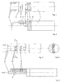
- Fig. 1 shows a section of a device according to the invention for coating a hollow body in a first embodiment.
- the spray head 2 comprises a cylindrical portion 3 and a perpendicular thereto section 4, which forms a planar guide surface 5, in which a total of eight openings 6 are provided for the discharge of compressed air, which are arranged in two rows parallel to each other and by means of a compressed air supply eighth be supplied with compressed air.
- a compressed air supply eighth be supplied with compressed air.
- two wires 7 of coating material come out at an acute angle from the cylindrical portion 3 of the spray head 2, wherein the ends are positioned at a defined distance from each other.
- the cylindrical portion 3 of the spray head 2 and the base body 1 has two internal channels (not shown for the main body), through which the wires 7 are led to a (not shown) feeding device, which is for a continuous tracking the coating wires 7 during the coating process provides.
- the tubes (9) represent a compressed air discharge, through which the air previously supplied through the openings 6, including any existing overspray or other impurities is discharged again.
- a voltage is generated between the two coating wires 7 that is high enough to generate an arc between their two ends. Due to the associated high temperatures, the material of the wires is melted.
- the compressed air supply 8 air is supplied under high pressure, which emerges from the openings 6.
- the emerging from the series with five openings 6 compressed air is primarily intended to detect the drops of the molten coating material and on the inner wall of a Hollow body (not shown), in which the device has been introduced to transport.
- the compressed air emerging from the row with three openings 6 is likewise directed towards the inner wall of the hollow body and is provided there to remove any impurities present, for example overspray.
- the compressed air including the impurities is then discharged through the serving as a compressed air discharge pipes 9.
- the discharge of the compressed air is effected by the pressure generated in the interior of the hollow body.
- both the openings 6, including the wire ends, and the openings 6 serving as compressed air outlets perform a helical movement, whereby the compressed air flow emerging from the row with three openings 6 precedes the spray jet of molten coating material (in linear movement direction) , This compressed air flow thus continuously cleans that portion of the inner wall of the hollow body 2, which is coated directly below by means of the spray jet.
- the coating apparatus according to the Fig. 2 has in addition to the eight openings 6 'two further compressed air outlets 10', which generate further compressed air flows for cleaning purposes, the compressed air outlets 10 '- pointing in the direction of the front end of the device - are executed angled by 45 °.
Landscapes
- Chemical & Material Sciences (AREA)
- Engineering & Computer Science (AREA)
- Physics & Mathematics (AREA)
- Plasma & Fusion (AREA)
- Chemical Kinetics & Catalysis (AREA)
- Materials Engineering (AREA)
- Mechanical Engineering (AREA)
- Metallurgy (AREA)
- Organic Chemistry (AREA)
- Electromagnetism (AREA)
- Nozzles (AREA)
- Application Of Or Painting With Fluid Materials (AREA)
Abstract
Description
- Die Erfindung betrifft eine Vorrichtung zum Beschichten von Bauteilen.
- Zur Erzeugung von Oberflächen hoher Güte an Bauteilen werden diese vielfach beschichtet. Hierbei wird ein Werkstoff in einer regelmäßig nur wenige µm betragen Schicht auf ein Trägerbauteil aufgetragen, um beispielsweise die Verschleißfestigkeit zu erhöhen oder der Bauteiloberfläche bestimmte Eigenschaften (z.B. elektrische Leitfähigkeit) zu verleihen.
- Verschiedene Beschichtungsverfahren sind bekannt, wobei insbesondere thermische Beschichtungsverfahren, bei denen der Beschichtungswerkstoff aufgeschmolzen und anschließend - regelmäßig mittels eines Druckluft- oder sonstigen Gasstroms - zerstäubt und auf die zu beschichtende Oberfläche transportiert wird, zum Einsatz kommen. Bekannte thermische Beschichtungsverfahren sind das Plasmabeschichten, das Hochgeschwindigkeits-Flammspritzen und das Lichbogendrahtspritzen.
- Aus
DE 198 41 617 A1 ist eine Lichtbogendrahtspritzanlage zur Beschichtung von Innenflächen bekannt. - Die darin offenbarte Lichtbogenspritzanlage weist einen rotierend angetriebenen Brennerschaft in Form einer Hohlwelle auf, die in den zu beschichtenden Hohlraum eingeführt wird. Am unteren Ende des Brennerschafts ist eine radial ausgerichtete Düse vorgesehen, durch die die Tropfen des aufgeschmolzenen Beschichtungswerkstoffs mittels Drucklufts, die durch das hohle Innere des Brennerschafts zugeführt wird, ausgetragen wird.
- Oberhalb des Brennerschafts ist eine Nachschubeinrichtung mit zwei Drahtrollen an diesem befestigt. Ausgehend von den Drahtrollen werden die zwei Drähte parallel zur Längsachse des Brennerschafts bis zu dessen Spitze geführt. Dort wird mittels einer elektrischen Hochspannung ein Lichtbogen zwischen den zwei Drahtenden erzeugt, der das Drahtmaterial aufschmilzt. Die Tropfen des aufgeschmolzenen Drahts werden dann von der Druckluftströmung erfasst und durch die Düse ausgetragen. Die Nachschubeinrichtung sorgt für eine kontinuierliche Versorgung des Brenners mit Beschichtungsmaterial.
- Die aus dem Stand der Technik bekannten Vorrichtungen zum Beschichten von Bauteilen produzieren eine nicht unerhebliche Menge an Overspray. Bei Overspray handelt es sich um Partikel des Beschichtungswerkstoffs, die keine ausreichend feste Bindung mit der zu beschichtenden Oberfläche eingehen. In der Regel ist dies die Folge von zu kleinen Partikelgrößen oder einem zu großen Abstand zwischen dem Brenner und der zu beschichtenden Oberfläche mit der Folge, dass die Temperatur der Partikel für eine ausreichende Haftung an der Oberfläche zu weit gesunken ist.
- Der Overspray wird in der Regel spätestens nach dem Beschichtungsprozess mittels einer großen, "globalen" Absaugvorrichtung abgesaugt. Diese Absaugvorrichtungen weisen jedoch den Nachteil auf, dass sie sehr leistungsfähig ausgelegt werden müssen, um sämtlichen Overspray von der beschichteten Fläche zu entfernen. Leistungsfähige Absaugvorrichtungen sind jedoch unter anderem mit entsprechend hohen Kosten verbunden. Ein Einsatz von leistungsschwächeren Absaugvorrichtungen kann jedoch insbesondere dann zu Problemen führen, wenn in mehreren Lagen beschichtet werden soll. In diesen Fällen kann es vorkommen, dass an der Oberfläche anliegender Overspray beim nachfolgenden Beschichtungsvorgang überschichtet wird, was an den betroffenen Stellen unter anderem in einer geringeren Schichthaftung resultiert.
- Ausgehend von diesem Stand der Technik liegt der Erfindung die Aufgabe zugrunde, eine Vorrichtung und ein Verfahren zum Beschichten von Bauteilen anzugeben, die eine Ablage von Overspray an den zu beschichtenden Oberflächen verringert.
- Diese Aufgabe wird durch eine Vorrichtung und ein Verfahren gemäß den unabhängigen Patentansprüchen gelöst. Vorteilhafte Ausführungsformen sind Gegenstand der jeweiligen abhängigen Ansprüche.
- Der Erfindung liegt der Gedanke zugrunde, bei einer Beschichtungsvorrichtung zum Beschichten von Bauteilen, wie sie aus dem Stand der Technik bekannt ist, den entstehenden Overspray mittel einer Druckgasströmung lokal zu entfernen.
- Die erfindungsgemäße Vorrichtung weist hierfür neben einer Druckgasdüse, die für den Transport des aufgeschmolzenen Beschichtungswerkstoffs vorgesehen ist, mindestens einen weiteren Druckgasauslass auf, der eine auf die zu beschichtende Oberfläche gerichtete Druckgasströmung erzeugt. Mittels dieser Druckgasströmung wird ein vorhandener Overspray lokal, d.h. an den Stellen, die zu dem betreffenden Zeitpunkt prozessbedingt (im Wesentlichen) frei von Overspray sein sollen, entfernt. Durch eine Beschränkung der Reinigung auf einen lokalen Bereich kann die Vorrichtung leistungsschwächer dimensioniert werden, als dies bei einer "globalen" Absaugvorrichtung der Fall wäre.
- Eine Verteilvorrichtung der erfindungsgemäße Beschichtungsvorrichtung weist somit neben der Druckgasdüse noch zumindest einen Brenner zum Aufschmelzen des Beschichtungswerkstoffs auf. Das aus der Druckgasdüse austretende Gas erfasst den hiermit aufgeschmolzenen Beschichtungswerkstoff, so dass ein entsprechender Sprühstrahl gebildet wird. Der Brenner kann beliebig ausgebildet sein; erfindungsgemäß werden darunter sämtliche Mittel verstanden, anhand derer der Beschichtungswerkstoff aufgeschmolzen werden kann.
- Vorzugsweise weist die Vorrichtung einen länglichen Grundkörper auf, an dem - bevorzugt in der Nähe eines der Enden - die Verteilvorrichtung befestigt ist. Eine solche Vorrichtung kann vorteilhaft in Hohlkörpern eingesetzt werden, die einen im Verhältnis zu der Längserstreckung geringen Querschnitt aufweisen (z.B. Zylinder in einem Motorblock). Die Querschnittsform des länglichen Grundkörpers kann beliebig ausgebildet sein. Fertigungstechnisch kann ein kreisförmiger Querschnitt vorteilhaft sein, da hierbei auf vorhandene Halbzeuge zurückgegriffen werden kann oder eine Herstellung mittels eines wenig aufwendigen Drehprozesses möglich ist.
- Vorteilhafterweise weist die Vorrichtung einen Rotationsantrieb für einen rotierenden Antrieb der Verteilvorrichtung auf; dies ermöglicht eine einfache Rundum-Beschichtung eines Hohlkörpers. Der Rotationsantrieb kann die Verteilvorrichtung direkt antreiben, d.h. ggf. relativ zu weiteren Bauteilen der Vorrichtung, beispielsweise dem länglichen Grundkörper. Beispielsweise kann der Sprühkopf einen ringförmigen Abschnitt aufweisen, der rotierend auf einem zylindrischen Abschnitt des Grundkörpers angeordnet ist. Dies ermöglicht eine besonders kompakte Bauweise, die einen Einsatz der Vorrichtung auch in Hohlräumen geringen Querschnitts zulässt. Der Rotationsantrieb kann alternativ für einen Antrieb der Verteilvorrichtung einschließlich weiterer Bauteile bis hin zur gesamten Vorrichtung ausgelegt sein. In einer besonders vorteilhaften Ausgestaltung treibt der Rotationsantrieb den länglichen Grundkörper einschließlich der hieran befestigten Verteilvorrichtung an. Dadurch kann ein vereinfachter Aufbau, insbesondere hinsichtlich der Verbindung zwischen dem Grundkörper und der Verteilvorrichtung erreicht werden.
- Die erfindungsgemäße Vorrichtung kann weiterhin Mittel zum Verfahren der Verteilvorrichtung entlang der zu beschichtenden Bauteiloberfläche aufweisen. Dadurch kann der von dem Sprühstrahl erfassbare Bereich deutlich vergrößert werden.
- In einer besonders bevorzugten Ausgestaltung weist die Vorrichtung einen länglichen Grundkörper mit einer hieran endseitig angeordneten Verteilvorrichtung, einen Rotationsantrieb für die Verteilvorrichtung und eine Vorrichtung, die ein Verfahren der Verteilvorrichtung, gegebenenfalls einschließlich des Grundkörpers in dessen Längsrichtung ermöglicht. Dadurch können auf vorteilhafte Weise insbesondere Hohlkörper mit einem rotationssymmetrischen Querschnitt und großer Längserstreckung (z.B. Hohlzylinder) beschichtet werden, wobei durch die Überlagerung der Rotations- und der Längsbewegung ein spiralförmiger Beschichtungsverlauf erzeugt wird.
- Bei einer entlang der Bauteiloberfläche verfahrbaren Verteilvorrichtung kann vorgesehen sein, dass die zum Entfernen des Oversprays vorgesehene Druckgasströmung dem Sprühstrahl aus Beschichtungswerkstoff in Verfahrrichtung vorgelagert ist. Auf diese Weise wird stets der als nächstes zu beschichtenden Abschnitt der Bauteiloberfläche von ggf. vorhandenem Overspray befreit.
- Der oder die weiteren Druckgasauslässe können so ausgebildet sein, dass eine beliebige Form der Druckgasströmung erzeugt wird. Beispielsweise kann eine ringförmige Druckgasströmung für den Fall vorgesehen werden, dass der/die weiteren Druckgasauslässe nicht mit der Verteilvorrichtung rotierend angetrieben werden. Andererseits kann die Strömung weiter fokussiert werden, wenn der/die weiteren Druckgasauslässe mit der Verteilvorrichtung gemeinsam (mit gleicher oder unterschiedlicher Winkelgeschwindigkeit) rotierend angetrieben werden. Der Druckgasstrom sollte dem Sprühstrahl in diesem Fall auch in Drehrichtung vorgelagert sein.
- Grundsätzlich kann der Druckgasauslass verstellbar ausgebildet sein, so dass die Richtung der Druckgasströmung insbesondere in Bezug zu der Bewegungsrichtung (rotatorisch sowie linear) der Verteilvorrichtung angepasst werden kann.
- In einer bevorzugten Ausführungsform weist die Vorrichtung ferner eine Absaugeinrichtung zum Absaugen des Druckgases einschließlich des Oversprays auf. Die Absaugvorrichtung kann beliebig ausgeführt werden. Vorteilhaft kann es sein, die Absaugvorrichtung in der Nähe der Auftreffstelle der Druckgasströmung auf die Bauteiloberfläche anzuordnen und insbesondere diese dem Druckgasauslass in dessen Bewegungsrichtung vorzulagern.
- In einer bevorzugten Ausführungsform ist eine Druckgaszufuhr in den länglichen Grundkörper der Vorrichtung integriert. Dieser kann hierzu insbesondere als Hohlzylinder ausgeführt sein.
- Bevorzugt ist die Druckgasdüse in der Verteilvorrichtung so ausgerichtet, dass der Sprühstrahl aus Beschichtungswerkstoff in Normalenrichtung bezogen auf den zu beschichtenden Oberflächenabschnitt ausgerichtet ist. Dadurch kann erreicht werden, dass die Tropfen des aufgeschmolzenen Beschichtungswerkstoffs, die von der Gasströmung erfasst und zu der zu beschichtenden Oberfläche transportiert werden, einen möglichst kurzen Weg bis zum Auftreffen auf die Oberfläche zurücklegen. Sie können daher beim Auftreffen sowohl eine noch möglichst hohe kinetische Energie als auch Temperatur aufweisen. Beides begünstigt die Oberflächenhaftung des Beschichtungswerkstoffs an der Oberfläche.
- Die Druckgasdüse kann beliebig ausgeführt sein. Beispielsweise kann diese als einfache Öffnung in einer Fläche ausgebildet sein. Alternativ kann die Druckgasdüse so ausgebildet sein, dass eine Beschleunigung und/oder Richtungssteuerung des austretenden Sprühstrahls bewirkt werden kann.
- In einer vorteilhaften Ausführungsform der vorliegenden Erfindung weist die Verteilvorrichtung eine Führungsfläche auf, die für eine gezielte Führung des Druckgasstroms sorgt. Die Ausgestaltung der Führungsfläche kann beispielsweise von der Form des zu beschichtenden Hohlkörpers, der Art des Brenners (z.B. Plasma-, Lichtbogenbrenner) und/oder des Beschichtungswerkstoffs abhängen. Beispielsweise kann die Führungsfläche eben ausgebildet sein, wobei die Austrittsrichtung des Sprühstrahls aus der Druckgasdüse senkrecht zu dieser ausgerichtet ist. Eine andere Ausgestaltung kann beispielsweise eine teilkreisförmige Führungsfläche vorsehen.
- In einer bevorzugten Ausführungsform ist die Druckgasdüse in die Führungsfläche integriert.
- Der (weitere) Druckgasauslass muss nicht in direkter Verbindung mit der Verteilvorrichtung stehen. Vielmehr können diese konstruktiv getrennte Elemente der Vorrichtung darstellen. Dies ermöglicht beispielsweise, die Verteilvorrichtung von einer Seite in einen an beiden Enden offenen Hohlzylinder einzuführen, während der Druckgasauslass von der anderen Seite eingebracht wird. Dies kann Vorteile hinsichtlich der Konstruktion der Vorrichtung bringen.
- Die Erfindung wird nachfolgend anhand von in den Zeichnungen dargestellten Ausführungsbeispielen näher erläutert.
- In den Zeichnungen zeigt
- Fig. 1
- eine erfindungsgemäße Vorrichtung gemäß einer ersten Ausführungsform in einer teilweise geschnittenen Draufsicht,
- Fig. 2
- die Vorrichtung der
Fig. 1 in einer teilweise geschnittenen Seitenansicht, - Fig. 3:
- eine erfindungsgemäße Vorrichtung gemäß einer zweiten Ausführungsform in einer Draufsicht,
- Fig. 4
- die Vorrichtung der
Fig. 3 in einer Schnittdarstellung entlang der Linie A-A und - Fig. 5
- die Vorrichtung der
Fig. 3 in einer Seitenansicht. -
Fig. 1 zeigt einen Ausschnitt aus einer erfindungsgemäßen Vorrichtung zur Beschichtung eines Hohlkörpers in einer ersten Ausführungsform. - Diese weist einen zylindrischen Grundkörper 1 mit einem endseitig hieran befestigten Sprühkopf 2 auf. Der Sprühkopf 2 umfasst einen zylindrischen Abschnitt 3 sowie einen hierzu senkrecht stehenden Abschnitt 4, der eine ebene Führungsfläche 5 bildet, in der insgesamt acht Öffnungen 6 für den Austritt von Druckluft vorgesehen sind, die in zwei Reihen parallel zueinander angeordnet sind und mittels einer Druckluftzufuhr 8 mit Druckluft versorgt werden. In einem Abstand parallel zu der Führungsfläche 5 treten zwei Drähte 7 aus Beschichtungswerkstoff in einem spitzen Winkel aus dem zylindrischen Abschnitt 3 des Sprühkopfs 2 heraus, wobei deren Enden in einem definierten Abstand zueinander positioniert sind. Zur Führung der Beschichtungsdrähte 7 weist der zylindrische Abschnitt 3 des Sprühkopfs 2 sowie der Grundkörper 1 zwei interne Kanäle (für den Grundkörper nicht dargestellt) auf, durch die die Drähte 7 bis zu einer (nicht dargestellten) Zuführvorrichtung geführt werden, die für eine kontinuierliche Nachführung der Beschichtungsdrähte 7 während des Beschichtungsvorgangs sorgt.
- Durch den Grundkörper 1 sowie den die Führungsfläche 5 bildenden Abschnitt 4 des Sprühkopfs 2 erstrecken sich zwei Rohre (9), die vorderseitig aus dem Sprühkopf 2heraustreten und dort um 90° abgewinkelt verlaufen. Die Rohre (9) stellen eine Druckluftabfuhr dar, durch die die zuvor durch die Öffnungen 6 zugeführte Luft einschließlich gegebenenfalls vorhandenen Oversprays oder sonstiger Verunreinigungen wieder abgeführt wird.
- Im Betrieb der Beschichtungsvorrichtung wird eine Spannung zwischen den zwei Beschichtungsdrähten 7 erzeugt, die so hoch ist, dass ein Lichtbogen zwischen deren zwei Enden erzeugt wird. Durch die damit verbundenen hohen Temperaturen wird der Werkstoff der Drähte aufgeschmolzen.
- Durch die Druckluftzufuhr 8 wird Luft unter hohem Druck zugeführt, die aus den Öffnungen 6 austritt. Die aus der Reihe mit fünf Öffnungen 6 austretende Druckluft ist primär dazu vorgesehen, die Tropfen des aufgeschmolzenen Beschichtungswerkstoffs zu erfassen und auf die Innenwandung eines Hohlkörpers(nicht dargestellt), in den die Vorrichtung eingeführt worden ist, zu transportieren. Die aus der Reihe mit drei Öffnungen 6 austretende Druckluft ist ebenfalls auf die Innenwandung des Hohlkörpers gerichtet und ist dazu vorgesehen dort gegebenenfalls vorhandene Verunreinigungen, beispielsweise Overspray zu entfernen. Die Druckluft einschließlich der Verunreinigungen wird daraufhin durch die als Druckluftabfuhr dienenden Rohre 9 abgeführt. Das Abführen der Druckluft erfolgt durch den im Inneren des Hohlkörpers erzeugten Überdruck.
- Während des Beschichtungsprozesses wird die gesamte dargestellte Vorrichtung mittels einer Antriebsvorrichtung sowohl rotierend als auch in Richtung ihrer Längsachse bewegt. Durch die Überlagerung dieser beiden Bewegungen führen sowohl die Öffnungen 6 einschließlich der Drahtenden als auch die als Druckluftauslässe dienenden Öffnungen 6 eine spiralförmige Bewegung aus, wobei die aus der Reihe mit drei Öffnungen 6 austretende Druckluftströmung dem Sprühstrahl aus aufgeschmolzenem Beschichtungswerkstoff (in linearer Bewegungsrichtung) vorgelagert sind. Diese Druckluftströmung reinigt somit kontinuierlich denjenigen Abschnitt der Innenwandung des Hohlkörpers 2, der direkt nachfolgend mittels des Sprühstrahls beschichtet wird.
- Die Beschichtungsvorrichtung gemäß der
Fig. 2 weist neben den acht Öffnungen 6' zwei weitere Druckluftauslässe 10' auf, die weitere Druckluftströmungen zu Reinigungszwecken erzeugen, wobei die Druckluftauslässe 10' - in Richtung des vorderen Endes der Vorrichtung weisend - um 45° abgewinkelt ausgeführt sind. - Im Gegensatz zu der Vorrichtung gemäß
Fig. 1 weisen die als Druckluftabfuhr vorgesehenen Rohre 9' bei der Vorrichtung derFig. 2 keinen um 90° gekrümmten Verlauf auf, sondern sind gerade nach vorne gerichtet ausgeführt.
Claims (12)
- Vorrichtung zum Beschichten eines Bauteils, mit einer Verteilvorrichtung für den Beschichtungswerkstoff, die einen Brenner zum Aufschmelzen des Beschichtungswerkstoffs und mindestens eine Druckgasdüse (6, 6') für den Transport des aufgeschmolzenen Beschichtungswerkstoffs aufweist, so dass ein auf die zu beschichtende Oberfläche gerichteter Sprühstrahl aus aufgeschmolzenem Beschichtungswerkstoff erzeugt wird, gekennzeichnet durch mindestens einen zweiten Druckgasauslass (6, 10'), der eine auf die zu beschichtende Oberfläche gerichtete Druckgasströmung erzeugt.
- Vorrichtung gemäß Anspruch 1, gekennzeichnet durch einen länglichen Grundkörper (1) an dem die Verteilvorrichtung endseitig angeordnet ist.
- Vorrichtung gemäß Anspruch 2, gekennzeichnet durch einen Rotationsantrieb für einen rotierenden Antrieb der Verteilvorrichtung.
- Vorrichtung gemäß Anspruch 2 und 3, dadurch gekennzeichnet, dass die Verteilvorrichtung um die Längsachse des Grundkörpers (1) rotierend angetrieben wird.
- Vorrichtung gemäß einem der vorhergehenden Ansprüche, gekennzeichnet durch Mittel zum Verfahren der Verteilvorrichtung entlang der Bauteiloberfläche.
- Vorrichtung gemäß Anspruch 3 und 5 dadurch gekennzeichnet, dass die Verteilvorrichtung entlang ihrer Rotationsachse verfahren wird.
- Vorrichtung gemäß Anspruch 5 oder 6, dadurch gekennzeichnet, dass die Druckgasströmung dem Sprühstrahl aus aufgeschmolzenem Beschichtungswerkstoff in Verfahrrichtung der Verteilvorrichtung vorgelagert ist.
- Vorrichtung gemäß einem der vorhergehenden Ansprüche, gekennzeichnet durch eine Absaugvorrichtung.
- Vorrichtung gemäß Anspruch 5 und 8, dadurch gekennzeichnet, dass die Absaugvorrichtung der Druckgasdüse (6, 6') und/oder dem zweiten Druckgasauslass (6, 10') in Verfahrrichtung der Verteilvorrichtung vorgelagert ist.
- Vorrichtung gemäß einem der vorhergehenden Ansprüche, gekennzeichnet durch eine im Inneren des Grundkörpers (1) angeordnete Druckgaszufuhr (8) für die Druckgasdüse (6, 6') und/oder den zweiten Druckgasauslass (6, 10').
- Vorrichtung gemäß einem der vorhergehenden Ansprüche, dadurch gekennzeichnet, dass die Druckgasdüse (6, 6') so ausgerichtet ist, dass der Sprühstrahl in Normalenrichtung auf die zu beschichtende Oberfläche gerichtet ist.
- Verfahren zum Beschichten eines Bauteils, wobei mit einer Verteilvorrichtung ein Beschichtungswerkstoff auf eine Oberfläche des Bauteils aufgebracht wird, indem der Beschichtungswerkstoff mittels eines Brenners zunächst aufgeschmolzen und dann mittels eines Druckgasstroms auf die Oberfläche transportiert wird und wobei eine Beschichtung in mehreren Beschichtungsvorgängen erfolgt, dadurch gekennzeichnet, dass vor jedem Beschichtungsvorgang Verschmutzungen auf der zu beschichtenden Oberfläche mittels eines Druckgasstroms beseitigt werden.
Applications Claiming Priority (1)
| Application Number | Priority Date | Filing Date | Title |
|---|---|---|---|
| DE102006059900A DE102006059900A1 (de) | 2006-12-19 | 2006-12-19 | Vorrichtung und Verfahren zum Beschichten von Bauteilen |
Publications (3)
| Publication Number | Publication Date |
|---|---|
| EP1936003A2 true EP1936003A2 (de) | 2008-06-25 |
| EP1936003A3 EP1936003A3 (de) | 2008-10-15 |
| EP1936003B1 EP1936003B1 (de) | 2013-01-02 |
Family
ID=38924812
Family Applications (1)
| Application Number | Title | Priority Date | Filing Date |
|---|---|---|---|
| EP07021513A Active EP1936003B1 (de) | 2006-12-19 | 2007-11-06 | Vorrichtung und Verfahren zum Beschichten von Bauteilen |
Country Status (2)
| Country | Link |
|---|---|
| EP (1) | EP1936003B1 (de) |
| DE (1) | DE102006059900A1 (de) |
Cited By (2)
| Publication number | Priority date | Publication date | Assignee | Title |
|---|---|---|---|---|
| WO2018223419A1 (en) * | 2017-06-09 | 2018-12-13 | Bmw Brilliance Automotive Ltd. | Arc wire spraying method, equipment and product |
| DE102019004085A1 (de) * | 2019-06-08 | 2020-12-10 | Daimler Ag | Vorrichtung zum thermischen Beschichten einer Zylinderbohrung |
Families Citing this family (3)
| Publication number | Priority date | Publication date | Assignee | Title |
|---|---|---|---|---|
| DE202010016599U1 (de) * | 2010-12-15 | 2012-03-16 | Leoni Bordnetz-Systeme Gmbh | Vorrichtung zum Aufspritzen einer Struktur aus leitfähigem Material auf ein Substrat |
| DE102014006723B4 (de) | 2014-05-07 | 2023-01-26 | Mercedes-Benz Group AG | Verfahren zum Visualisieren und Reinigen von Verunreinigungen |
| DE102017120397A1 (de) * | 2017-09-05 | 2019-03-07 | Gebr. Heller Maschinenfabrik Gmbh | Vorrichtung und Verfahren zum Lichtbogendrahtspritzen |
Citations (6)
| Publication number | Priority date | Publication date | Assignee | Title |
|---|---|---|---|---|
| WO1991012183A1 (en) | 1990-02-12 | 1991-08-22 | Tafa Incorporated | Inside diameter arc spray gun |
| WO1997049497A1 (en) | 1996-06-24 | 1997-12-31 | Tafa, Incorporated | Apparatus for rotary spraying a metallic coating |
| EP0949036A2 (de) | 1998-03-11 | 1999-10-13 | Sulzer Metco (US) Inc. | Verlängerung eines thermischen Lichtbogenspritzbrenners und Gasstrahlselement dafür |
| US20030161946A1 (en) | 2002-02-11 | 2003-08-28 | Moore Karen A. | Systems and methods for coating conduit interior surfaces utilizing a thermal spray gun with extension arm |
| US20040231596A1 (en) | 2003-05-19 | 2004-11-25 | George Louis C. | Electric arc spray method and apparatus with combustible gas deflection of spray stream |
| FR2866901A1 (fr) | 2004-02-27 | 2005-09-02 | Peugeot Citroen Automobiles Sa | Dispositif de projection de particules metalliques par arc electrique entre deux fils |
Family Cites Families (2)
| Publication number | Priority date | Publication date | Assignee | Title |
|---|---|---|---|---|
| DE808310C (de) * | 1949-07-30 | 1951-07-12 | Carola Doernemann | Rotierende Zerstaeubungswinkelduese fuer Metallspritzpistolen |
| DE19841617A1 (de) | 1998-09-11 | 2000-03-23 | Daimler Chrysler Ag | Rotierende Drahtlichtbogenspritzanlage zur Beschichtung von Innenflächen |
-
2006
- 2006-12-19 DE DE102006059900A patent/DE102006059900A1/de not_active Withdrawn
-
2007
- 2007-11-06 EP EP07021513A patent/EP1936003B1/de active Active
Patent Citations (6)
| Publication number | Priority date | Publication date | Assignee | Title |
|---|---|---|---|---|
| WO1991012183A1 (en) | 1990-02-12 | 1991-08-22 | Tafa Incorporated | Inside diameter arc spray gun |
| WO1997049497A1 (en) | 1996-06-24 | 1997-12-31 | Tafa, Incorporated | Apparatus for rotary spraying a metallic coating |
| EP0949036A2 (de) | 1998-03-11 | 1999-10-13 | Sulzer Metco (US) Inc. | Verlängerung eines thermischen Lichtbogenspritzbrenners und Gasstrahlselement dafür |
| US20030161946A1 (en) | 2002-02-11 | 2003-08-28 | Moore Karen A. | Systems and methods for coating conduit interior surfaces utilizing a thermal spray gun with extension arm |
| US20040231596A1 (en) | 2003-05-19 | 2004-11-25 | George Louis C. | Electric arc spray method and apparatus with combustible gas deflection of spray stream |
| FR2866901A1 (fr) | 2004-02-27 | 2005-09-02 | Peugeot Citroen Automobiles Sa | Dispositif de projection de particules metalliques par arc electrique entre deux fils |
Cited By (3)
| Publication number | Priority date | Publication date | Assignee | Title |
|---|---|---|---|---|
| WO2018223419A1 (en) * | 2017-06-09 | 2018-12-13 | Bmw Brilliance Automotive Ltd. | Arc wire spraying method, equipment and product |
| US10941478B2 (en) | 2017-06-09 | 2021-03-09 | Bmw Brilliance Automotive Ltd. | Arc wire spraying method, equipment and product |
| DE102019004085A1 (de) * | 2019-06-08 | 2020-12-10 | Daimler Ag | Vorrichtung zum thermischen Beschichten einer Zylinderbohrung |
Also Published As
| Publication number | Publication date |
|---|---|
| DE102006059900A1 (de) | 2008-07-03 |
| EP1936003B1 (de) | 2013-01-02 |
| EP1936003A3 (de) | 2008-10-15 |
Similar Documents
| Publication | Publication Date | Title |
|---|---|---|
| EP2953732B1 (de) | Applikationsverfahren und applikationsanlage | |
| DE2452684C2 (de) | Verfahren und Vorrichtung zur gleichmäßigen Verteilung eines Stromes zerstäubter Teilchen auf einem Substrat | |
| DE102008024313A1 (de) | Verfahren zur Vorkonditionierung einer zu beschichtenden Oberfläche | |
| EP1936003B1 (de) | Vorrichtung und Verfahren zum Beschichten von Bauteilen | |
| DE102017213359B4 (de) | Prozessbox zum thermischen Beschichten einer metallischen Innenraum-Oberfläche,Beschichtungsanlage zum thermischen Beschichten eines Zylinderkurbelgehäuses für eine Verbrennungskraftmaschine und Verfahren zum thermischen Beschichten einer metallischen Innenraum-Oberfläche eines Objekts | |
| EP2106456A2 (de) | Verfahren und vorrichtung zum beschichten eines hohlkörpers | |
| EP3047914A1 (de) | Anlage und Verfahren zur metallischen Beschichtung eines Werkstückes | |
| DE102006052824B4 (de) | Verfahren und Vorrichtung beim Laserstrahlschneiden eines metallischen Bauteils | |
| DE102014209172B4 (de) | Vorrichtung zum Fokussieren eines aus einer Ausgabeöffnung einer Ausgabevorrichtung einer Jet-Vorrichtung ausgegebenen viskosen Mediums, Jet-System und Produktionsanlage | |
| DE102008052102A1 (de) | Vorrichtung zum Vor- und/oder Nachbehandeln einer Bauteiloberfläche mittels eines Plasmastrahls | |
| EP1980328B1 (de) | Vorrichtung zum Beschichten von Bauteilen | |
| DE102007019509B3 (de) | Vorrichtung zum Beschichten der Innenwand eines Hohlkörpers | |
| EP2153910A1 (de) | Verfahren und System zum Lackieren von Werkstücken | |
| DE102007004416B4 (de) | Vorrichtung zum Beschichten von Hohlkörpern | |
| DE102004038173A1 (de) | Verfahren zum thermischen Spritzen von Zylinderlaufflächen bei mehrreihigen Motoren | |
| WO2018114952A1 (de) | Düsenaufbau für das thermische spritzen mittels einer suspension oder einer präcursorlösung | |
| DE102004038179A1 (de) | Verfahren zur Herstellung einer thermisch beschichteten Zylinderlauffläche mit einer Einfuhrfase | |
| DE102006056230B4 (de) | Vorrichtung zum Innenbeschichten eines Hohlkörpers | |
| DE102011114395A1 (de) | Vorrichtung zum thermischen Beschichten | |
| DE1577617A1 (de) | Elektrostatische Spritzvorrichtung fuer Farbmaterial u. dgl. | |
| DE10327429A1 (de) | Ultraschall-Stehwellen-Zerstäuberanordnung | |
| DE102009005082A1 (de) | Vorrichtung und Verfahren zum Lichtbogendrahtspritzen | |
| EP1354633A1 (de) | Sprühbeschichtungsvorrichtung mit hohler Elektrode | |
| WO2019048431A1 (de) | Vorrichtung und verfahren zum lichtbogendrahtspritzen | |
| EP1980331B1 (de) | Verfahren und Vorrichtung zur Beschichtung von Bauteiloberflächen |
Legal Events
| Date | Code | Title | Description |
|---|---|---|---|
| PUAI | Public reference made under article 153(3) epc to a published international application that has entered the european phase |
Free format text: ORIGINAL CODE: 0009012 |
|
| AK | Designated contracting states |
Kind code of ref document: A2 Designated state(s): AT BE BG CH CY CZ DE DK EE ES FI FR GB GR HU IE IS IT LI LT LU LV MC MT NL PL PT RO SE SI SK TR |
|
| AX | Request for extension of the european patent |
Extension state: AL BA HR MK RS |
|
| PUAL | Search report despatched |
Free format text: ORIGINAL CODE: 0009013 |
|
| AK | Designated contracting states |
Kind code of ref document: A3 Designated state(s): AT BE BG CH CY CZ DE DK EE ES FI FR GB GR HU IE IS IT LI LT LU LV MC MT NL PL PT RO SE SI SK TR |
|
| AX | Request for extension of the european patent |
Extension state: AL BA HR MK RS |
|
| 17P | Request for examination filed |
Effective date: 20081030 |
|
| 17Q | First examination report despatched |
Effective date: 20081217 |
|
| AKX | Designation fees paid |
Designated state(s): DE FR GB IT |
|
| REG | Reference to a national code |
Ref country code: DE Ref legal event code: R079 Ref document number: 502007011137 Country of ref document: DE Free format text: PREVIOUS MAIN CLASS: C23C0004160000 Ipc: B05B0015040000 |
|
| RIC1 | Information provided on ipc code assigned before grant |
Ipc: C23C 4/12 20060101ALI20120309BHEP Ipc: B05B 7/22 20060101ALI20120309BHEP Ipc: B05B 15/04 20060101AFI20120309BHEP Ipc: B05B 13/06 20060101ALI20120309BHEP Ipc: C23C 4/16 20060101ALI20120309BHEP |
|
| GRAP | Despatch of communication of intention to grant a patent |
Free format text: ORIGINAL CODE: EPIDOSNIGR1 |
|
| RIN1 | Information on inventor provided before grant (corrected) |
Inventor name: SCHREIER, EMIL Inventor name: WAGENER, WOLFRAM |
|
| GRAS | Grant fee paid |
Free format text: ORIGINAL CODE: EPIDOSNIGR3 |
|
| GRAA | (expected) grant |
Free format text: ORIGINAL CODE: 0009210 |
|
| AK | Designated contracting states |
Kind code of ref document: B1 Designated state(s): DE FR GB IT |
|
| REG | Reference to a national code |
Ref country code: GB Ref legal event code: FG4D Free format text: NOT ENGLISH |
|
| REG | Reference to a national code |
Ref country code: DE Ref legal event code: R096 Ref document number: 502007011137 Country of ref document: DE Effective date: 20130314 |
|
| PLBE | No opposition filed within time limit |
Free format text: ORIGINAL CODE: 0009261 |
|
| STAA | Information on the status of an ep patent application or granted ep patent |
Free format text: STATUS: NO OPPOSITION FILED WITHIN TIME LIMIT |
|
| 26N | No opposition filed |
Effective date: 20131003 |
|
| REG | Reference to a national code |
Ref country code: DE Ref legal event code: R097 Ref document number: 502007011137 Country of ref document: DE Effective date: 20131003 |
|
| REG | Reference to a national code |
Ref country code: FR Ref legal event code: PLFP Year of fee payment: 9 |
|
| REG | Reference to a national code |
Ref country code: FR Ref legal event code: PLFP Year of fee payment: 10 |
|
| REG | Reference to a national code |
Ref country code: FR Ref legal event code: PLFP Year of fee payment: 11 |
|
| REG | Reference to a national code |
Ref country code: DE Ref legal event code: R079 Ref document number: 502007011137 Country of ref document: DE Free format text: PREVIOUS MAIN CLASS: B05B0015040000 Ipc: B05B0014000000 |
|
| P01 | Opt-out of the competence of the unified patent court (upc) registered |
Effective date: 20230502 |
|
| PGFP | Annual fee paid to national office [announced via postgrant information from national office to epo] |
Ref country code: DE Payment date: 20251110 Year of fee payment: 19 |
|
| PGFP | Annual fee paid to national office [announced via postgrant information from national office to epo] |
Ref country code: GB Payment date: 20251120 Year of fee payment: 19 |
|
| PGFP | Annual fee paid to national office [announced via postgrant information from national office to epo] |
Ref country code: IT Payment date: 20251128 Year of fee payment: 19 |
|
| PGFP | Annual fee paid to national office [announced via postgrant information from national office to epo] |
Ref country code: FR Payment date: 20251125 Year of fee payment: 19 |