EP1936018B1 - System for screwless fixing of a body to a panel - Google Patents
System for screwless fixing of a body to a panel Download PDFInfo
- Publication number
- EP1936018B1 EP1936018B1 EP07122872.0A EP07122872A EP1936018B1 EP 1936018 B1 EP1936018 B1 EP 1936018B1 EP 07122872 A EP07122872 A EP 07122872A EP 1936018 B1 EP1936018 B1 EP 1936018B1
- Authority
- EP
- European Patent Office
- Prior art keywords
- locking member
- panel
- formation
- retaining
- opening
- Prior art date
- Legal status (The legal status is an assumption and is not a legal conclusion. Google has not performed a legal analysis and makes no representation as to the accuracy of the status listed.)
- Not-in-force
Links
- 230000015572 biosynthetic process Effects 0.000 claims description 57
- 238000005755 formation reaction Methods 0.000 claims description 57
- 238000006073 displacement reaction Methods 0.000 claims description 8
- 238000005406 washing Methods 0.000 description 9
Images






Classifications
-
- D—TEXTILES; PAPER
- D06—TREATMENT OF TEXTILES OR THE LIKE; LAUNDERING; FLEXIBLE MATERIALS NOT OTHERWISE PROVIDED FOR
- D06F—LAUNDERING, DRYING, IRONING, PRESSING OR FOLDING TEXTILE ARTICLES
- D06F37/00—Details specific to washing machines covered by groups D06F21/00 - D06F25/00
- D06F37/02—Rotary receptacles, e.g. drums
- D06F37/12—Rotary receptacles, e.g. drums adapted for rotation or oscillation about a vertical axis
- D06F37/18—Doors or covers; Securing means therefor
-
- D—TEXTILES; PAPER
- D06—TREATMENT OF TEXTILES OR THE LIKE; LAUNDERING; FLEXIBLE MATERIALS NOT OTHERWISE PROVIDED FOR
- D06F—LAUNDERING, DRYING, IRONING, PRESSING OR FOLDING TEXTILE ARTICLES
- D06F37/00—Details specific to washing machines covered by groups D06F21/00 - D06F25/00
- D06F37/26—Casings; Tubs
- D06F37/28—Doors; Security means therefor
-
- D—TEXTILES; PAPER
- D06—TREATMENT OF TEXTILES OR THE LIKE; LAUNDERING; FLEXIBLE MATERIALS NOT OTHERWISE PROVIDED FOR
- D06F—LAUNDERING, DRYING, IRONING, PRESSING OR FOLDING TEXTILE ARTICLES
- D06F37/00—Details specific to washing machines covered by groups D06F21/00 - D06F25/00
- D06F37/42—Safety arrangements, e.g. for stopping rotation of the receptacle upon opening of the casing door
Definitions
- the present invention relates to a system for screwless fixing of a body having a projecting formation, such as the body of a door-locking device for a washing machine, to a panel with an opening, for example a front panel of a washing machine, of the kind defined in the preamble of claim 1.
- EP-A- 1 418 266 discloses such a system wherein pins resiliently carried by the body engage corresponding holes in the panel.
- the object of the present invention is to provide a screwless fixing system of the improved type, implementation of which is particularly simple and operation of which is reliable and secure.
- the locking member is displaceable from the pre-engagement position into the engaged position essentially by means of a translation.
- the locking member is displaceable from the pre-engagement position into the engaged position by means of a rotation about an axis essentially parallel to the panel.
- FIG. 1 denotes overall a door-locking device for a washing machine, in particular a clothes washing machine, for example of the type described in the European Patent Application EP 1 544 387 A2 or in the application EP 1 467 048 A1 , both in the name of the same Applicant.
- the projecting formation 3 of the door-locking device has an essentially rectangular general shape, with a main axis or direction indicated by A-A in Figure 1 .
- the door-locking device 1 is intended to be fixed to a front panel of the washing machine, for example the panel indicated by 5 in Figures 4 to 9 .
- This panel has an opening 6, which also has an essentially rectangular shape.
- the projecting formation 3 of the door-locking device has a head portion 3a which, in the direction of the axis A-A, has an extension greater than the corresponding larger dimension of the opening 6 of the panel 5.
- the projecting formation 3 also has a neck portion, indicated by 3b (see, for example, Figures 3 , 4a and 4b ) which in the direction of the axis A-A has an extension which is smaller than or at the most essentially the same as the larger dimension of the opening 6 of the panel 5.
- a locking member is associated with the plate-shaped body 2 of the door-locking device.
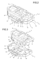
- the locking member 7 comprises an essentially plate-shaped body 8 which, on its periphery, has a plurality of resilient eyelet lugs 9 which are able to snap-engage with corresponding projections 10 of the body 2 of the door-locking device 1 (see in particular Figures 1 to 3 ).
- the body 8 of the locking member 7 also has a plurality of resilient retaining formations 11, the distal end of which has a laterally projecting tooth-like formation 11 a with an inclined end surface 11b.
- the plate-shaped body 2 of the door-locking device 1 has a corresponding plurality of openings 12 ( Figures 1 , 3 , 4b, 5b , 10 ). These openings have an outer part , namely the retaining formation or formations 12a ( Figures 4b, 5b , 6b, 7 , 8b ) with an inclined inner surface 12b.
- the arrangement is such that the locking member 7 is able to assume, relative to the body 2 of the door-locking device 1, a pre-engagement position, shown in Figures 1 , 2 and 4a to 7 .
- the resilient formations of the locking member 7 are engaged with the corresponding projections 10 of the door-locking device 1, as is shown in Figures 1 and 2
- the retaining formations 11 of the locking member have respective inclined end surfaces 11 b which rest against the corresponding inclined surfaces 12b of the openings 12 of the door-locking device, as can be seen in particular in Figures 1 , 4b , 5b , 6b , 7 and 8b .
- the retaining formations 11 are moreover disengaged from - or not engaged with - the reataining formation or formations 12a of the door-locking device.
- the door-locking device 1 is conveniently engaged with the opening 6 of the panel 5 of the machine while the associated locking member is mounted thereon and is situated in the pre-engagement position described above.
- Mounting of the door-locking device is performed in particular in the manner described below.
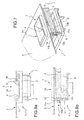
- the projecting formation 3 of the door-locking device is passed, in an inclined position, through the opening 6 of the panel 5.
- the door-locking device 1 is then rotated in the direction of the panel 5, as shown in Figures 5a and 5b , until the projecting formation 3 is positioned beyond this panel.
- the door-locking device 1, with the associated locking member 7 in the pre-engagement position is then displaced, towards the right when viewing Figures 5a and 5b , until the engaged position shown in Figures 6a, 6b and 7 is reached. In this condition, both the ends of the head portion 3a of the projecting formation 3 extend outside the opening 6 of the panel 5 ( Figure 6a ).
- a step indicated by 13 is formed (see in particular Figures 1 and, for example, 6a) able to be arranged so as to bear against a corresponding side of the opening 6 of the panel 5 ( Figure 6a ).
- the locking member 7 may be manually displaced from the pre-engagement position, into an engaged and locked position, by means of displacement thereof in the direction of the said door-locking device and therefore in the direction of the panel 5.
- the tooth-like ends 11 a of the retaining formations 11 of the locking member 7 pass over the associated retaining formation or formations 12a of the body 2 of the door-locking device, snap-engaging with a stable retaining engagement beyond said walls and coming into contact with the surface of the panel 5 situated on the opposite side to the projecting formation 3 ( Figures 8a, 8b and 9 ).
- the door-locking device and the associated locking member are firmly fastened to the panel 5 and displacement thereof relative to this panel is prevented.
- the body 2 of the door-locking device has a plurality of openings 14 inside which corresponding, essentially cylindrical, relief formations 15 of the body 8 of the locking member 7 are able to extend in a guided manner.
- the formations 15, as can be seen in Figure 10 may if necessary project beyond the body 2 of the door-locking device when the latter is fastened to the panel 5 following the arrangement of the locking member 7 in the engaged position described above.
- the ends of the formations 15 may then press against the inner surface of the panel 5 or if necessary engage inside corresponding openings provided in this panel.
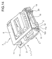
- Figures 11 to 19 show a variation of embodiment where the locking member 7 is able to pass from the pre-engagement position, shown in Figures 11 , 12 , 14b-16b as a result of a relative rotation thereof with respect to the body 2 of the door-locking device, about an axis essentially parallel to the panel 5.
- the body 2 of the door-locking device has two openings 16 which are aligned together in a direction B essentially perpendicular to the axis A-A of the projecting formation 3 and the corresponding opening 4.
- Respective cylindrical reliefs 17, aligned and facing each other in the direction B-B, extend inside the openings 16.
- two resilient engaging lugs 18 extend from the body 8 of the locking member 7, essentially in the form of elongated eyelets able to extend inside the openings 16, engaging around the reliefs 17 (see, for example, Figures 13 and 15a ).
- the aligned reliefs or pins 17 define therefore an axis of relative rotation of the locking member 7 with respect to the body 2 of the door-locking device 1.
- the body 2 of the door-locking device has a plurality of openings 19 (see, for example, Figures 11 , 13 , 14 , 15b , 16b and 18 ) through which corresponding opposition reliefs 20 extend and project from the body 8 of the locking member 7.
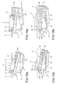
- the locking member 7 is able to assume, relative to the body 2 of the door-locking device 1, a pre-engagement position where the retaining formations 11 of the former rest against the inclined surfaces 12b of the corresponding retaining formations 12a of the latter (see, for example, Figures 15b ).
- the door-locking device may then be engaged with the opening 6 of the panel 5 in a manner similar to that described in relation to the first embodiment described previously.
- the head portion 3a of the projecting formation 3 of the door-locking device is passed through the opening 6 of the panel 5 in an inclined position and is then rotated ( Figures 16a, 16b ) until said projecting formation 3 is positioned completely beyond the panel 5.
- the opposition reliefs 20 of the locking member 7 are arranged against the surface or the side of the panel 5 opposite the projecting formation 3 ( Figures 16b ).
- the assembly formed by the door-locking device and the associated locking member 7 is then displaced, parallel to the panel 5, until the projecting formation 3 reaches the engaged position where its step 13 is arranged inside the opening 6 of the panel 5, along one side of this opening.
- the arrangement is such that, as a result of said displacement and reaching of the engaged position described above, following contact of the reliefs 20 against the panel 5, the locking member 7 automatically performs a rotation about the axis of the pins 17, passing into the condition shown in Figures 17a, 17b and 18 , where the end teeth 11 a of the retaining formations 11 have snap-engaged beyond the retaining formations 12a of the door-locking device and press against the panel 5, ensuring in fact stable fixing of the door-locking device to the panel. In this condition, owing to the engagement of the members 11 and 20 with the panel 5, any play between the device 1 and the panel is eliminated.
Landscapes
- Engineering & Computer Science (AREA)
- Textile Engineering (AREA)
- Connection Of Plates (AREA)
Applications Claiming Priority (1)
| Application Number | Priority Date | Filing Date | Title |
|---|---|---|---|
| IT000912A ITTO20060912A1 (it) | 2006-12-21 | 2006-12-21 | Sistema per il fissaggio senza viti di un corpo ad un pannello |
Publications (2)
| Publication Number | Publication Date |
|---|---|
| EP1936018A1 EP1936018A1 (en) | 2008-06-25 |
| EP1936018B1 true EP1936018B1 (en) | 2015-08-26 |
Family
ID=39256982
Family Applications (1)
| Application Number | Title | Priority Date | Filing Date |
|---|---|---|---|
| EP07122872.0A Not-in-force EP1936018B1 (en) | 2006-12-21 | 2007-12-11 | System for screwless fixing of a body to a panel |
Country Status (2)
| Country | Link |
|---|---|
| EP (1) | EP1936018B1 (it) |
| IT (1) | ITTO20060912A1 (it) |
Families Citing this family (11)
| Publication number | Priority date | Publication date | Assignee | Title |
|---|---|---|---|---|
| IT1398385B1 (it) * | 2009-02-11 | 2013-02-22 | Bitron Spa | Dispositivo blocca-porta, particolarmente per apparecchi elettrodomestici |
| SI23003A (sl) | 2009-03-06 | 2010-09-30 | ITW@METALFLEX@@d@o@o@@Tolmin | Priključna komponenta brezvijačne vtaknilne zveze |
| ITTO20120606A1 (it) * | 2012-07-09 | 2014-01-10 | Illinois Tool Works | Dispositivo fermaporta con una porzione di fissaggio senza viti |
| CN104075423B (zh) * | 2014-06-19 | 2017-10-13 | 珠海格力电器股份有限公司 | 手柄上盖、包含其的滑动手柄安装结构、手柄组件 |
| DE102016218812A1 (de) * | 2016-09-29 | 2018-03-29 | BSH Hausgeräte GmbH | Haushaltsgerät |
| CN121952397A (zh) * | 2017-07-04 | 2026-05-01 | 伊利诺斯工具制品有限公司 | 门锁和电气设备 |
| KR102889222B1 (ko) * | 2018-11-29 | 2025-11-20 | 일리노이즈 툴 워크스 인코포레이티드 | 도어록 및 전자 장치 |
| CN111236759B (zh) * | 2018-11-29 | 2023-01-24 | 伊利诺斯工具制品有限公司 | 门锁和电气设备 |
| DE102019007428B3 (de) * | 2019-10-24 | 2020-12-10 | Emz-Hanauer Gmbh & Co. Kgaa | Türverschluss für ein elektrisches Haushaltsgerät sowie Verfahren zur Montage eines solchen |
| IT202000002653A1 (it) * | 2020-02-11 | 2021-08-11 | Elettrotecnica Rold Srl | Dispositivo per la chiusura e apertura di sportelli, in particolare di sportelli di elettrodomestici quali lavatrici o simili |
| CN114059301B (zh) * | 2020-08-07 | 2025-03-25 | 孔繁婷 | 电器设备及其门锁 |
Family Cites Families (4)
| Publication number | Priority date | Publication date | Assignee | Title |
|---|---|---|---|---|
| DE2615512A1 (de) * | 1976-04-09 | 1977-10-20 | Licentia Gmbh | Elektrisches haushaltsgeraet mit einer schalterblende |
| ITMI20022369A1 (it) * | 2002-11-08 | 2004-05-09 | Elettrotecnica Rold Srl | Dispositivo di bloccaggio del portello di chiusura di una lavabiancheria |
| ITTO20030273A1 (it) | 2003-04-09 | 2004-10-10 | Bitron Spa | Dispositivo di bloccaggio e sbloccaggio del portello |
| ITTO20031021A1 (it) | 2003-12-18 | 2005-06-19 | Bitron Spa | Dispositivo blocca-porta a sicurezza incrementata, particolarmente per apparecchi elettrodomestici. |
-
2006
- 2006-12-21 IT IT000912A patent/ITTO20060912A1/it unknown
-
2007
- 2007-12-11 EP EP07122872.0A patent/EP1936018B1/en not_active Not-in-force
Also Published As
| Publication number | Publication date |
|---|---|
| EP1936018A1 (en) | 2008-06-25 |
| ITTO20060912A1 (it) | 2008-06-22 |
Similar Documents
| Publication | Publication Date | Title |
|---|---|---|
| EP1936018B1 (en) | System for screwless fixing of a body to a panel | |
| EP1418266B1 (en) | A device for locking the closure door of a washing machine | |
| TW201636517A (zh) | 安全鉤 | |
| US20150191932A1 (en) | Fixation of door locks without screws into home appliances | |
| WO2016088695A1 (ja) | 保持装置 | |
| RU2294995C2 (ru) | Запорный узел и сушильная машина с таким запорным узлом | |
| US20230118668A1 (en) | Fastening strap clamp assembly | |
| DE102004022978B4 (de) | Elektronikkomponente z.B. Herdschaltuhr | |
| US20070126259A1 (en) | Unit carrier comprising an integrated lock fixing system for a motor vehicle door | |
| US20090001735A1 (en) | Mechanism for Securing the Handle of a Door or Window | |
| JP5020726B2 (ja) | 二部材間の係止構造 | |
| KR20190051791A (ko) | 커넥터 어셈블리 및 그 제조 방법 | |
| KR200466962Y1 (ko) | 레버타입 커넥터 어셈블리 | |
| KR20070077665A (ko) | 클립 체결 구조 | |
| KR100761280B1 (ko) | 냉장고의 도어핸들결합체 | |
| JP2001349116A (ja) | ドアロック装置の操作ワイヤ保持装置 | |
| KR100559723B1 (ko) | 시프트 락 케이블 하우징 조립체 | |
| JP4167125B2 (ja) | 車両用ドアロック解除装置 | |
| HK1065830B (en) | A device for locking the closure door of a washing machine | |
| KR20100030416A (ko) | 레버타입 커넥터어셈블리 | |
| KR200147350Y1 (ko) | 냉장고용 핸들조립체 | |
| JP2008128391A (ja) | スタッド固定クリップ | |
| WO2020015912A1 (en) | Door fastened by micro switch pin | |
| EP3440254B1 (en) | A household appliance with improved safety | |
| KR20210051160A (ko) | 차량용 도어의 인사이드 핸들장치 |
Legal Events
| Date | Code | Title | Description |
|---|---|---|---|
| PUAI | Public reference made under article 153(3) epc to a published international application that has entered the european phase |
Free format text: ORIGINAL CODE: 0009012 |
|
| AK | Designated contracting states |
Kind code of ref document: A1 Designated state(s): AT BE BG CH CY CZ DE DK EE ES FI FR GB GR HU IE IS IT LI LT LU LV MC MT NL PL PT RO SE SI SK TR |
|
| AX | Request for extension of the european patent |
Extension state: AL BA HR MK RS |
|
| 17P | Request for examination filed |
Effective date: 20081217 |
|
| AKX | Designation fees paid |
Designated state(s): DE FR GB |
|
| 17Q | First examination report despatched |
Effective date: 20090218 |
|
| GRAP | Despatch of communication of intention to grant a patent |
Free format text: ORIGINAL CODE: EPIDOSNIGR1 |
|
| INTG | Intention to grant announced |
Effective date: 20150310 |
|
| RIN1 | Information on inventor provided before grant (corrected) |
Inventor name: PROMUTICO, FABRIZIO Inventor name: SACCOCCI, ANDREA |
|
| GRAS | Grant fee paid |
Free format text: ORIGINAL CODE: EPIDOSNIGR3 |
|
| GRAA | (expected) grant |
Free format text: ORIGINAL CODE: 0009210 |
|
| AK | Designated contracting states |
Kind code of ref document: B1 Designated state(s): DE FR GB |
|
| REG | Reference to a national code |
Ref country code: GB Ref legal event code: FG4D |
|
| REG | Reference to a national code |
Ref country code: DE Ref legal event code: R096 Ref document number: 602007042756 Country of ref document: DE |
|
| REG | Reference to a national code |
Ref country code: FR Ref legal event code: PLFP Year of fee payment: 9 |
|
| REG | Reference to a national code |
Ref country code: DE Ref legal event code: R097 Ref document number: 602007042756 Country of ref document: DE |
|
| PLBE | No opposition filed within time limit |
Free format text: ORIGINAL CODE: 0009261 |
|
| STAA | Information on the status of an ep patent application or granted ep patent |
Free format text: STATUS: NO OPPOSITION FILED WITHIN TIME LIMIT |
|
| 26N | No opposition filed |
Effective date: 20160530 |
|
| GBPC | Gb: european patent ceased through non-payment of renewal fee |
Effective date: 20151211 |
|
| PG25 | Lapsed in a contracting state [announced via postgrant information from national office to epo] |
Ref country code: GB Free format text: LAPSE BECAUSE OF NON-PAYMENT OF DUE FEES Effective date: 20151211 |
|
| REG | Reference to a national code |
Ref country code: FR Ref legal event code: PLFP Year of fee payment: 10 |
|
| PGFP | Annual fee paid to national office [announced via postgrant information from national office to epo] |
Ref country code: FR Payment date: 20161229 Year of fee payment: 10 |
|
| REG | Reference to a national code |
Ref country code: FR Ref legal event code: ST Effective date: 20180831 |
|
| PG25 | Lapsed in a contracting state [announced via postgrant information from national office to epo] |
Ref country code: FR Free format text: LAPSE BECAUSE OF NON-PAYMENT OF DUE FEES Effective date: 20180102 |
|
| PGFP | Annual fee paid to national office [announced via postgrant information from national office to epo] |
Ref country code: DE Payment date: 20191230 Year of fee payment: 13 |
|
| REG | Reference to a national code |
Ref country code: DE Ref legal event code: R119 Ref document number: 602007042756 Country of ref document: DE |
|
| PG25 | Lapsed in a contracting state [announced via postgrant information from national office to epo] |
Ref country code: DE Free format text: LAPSE BECAUSE OF NON-PAYMENT OF DUE FEES Effective date: 20210701 |