EP1936053A2 - Connecteur de trame de moment - Google Patents
Connecteur de trame de moment Download PDFInfo
- Publication number
- EP1936053A2 EP1936053A2 EP20070255025 EP07255025A EP1936053A2 EP 1936053 A2 EP1936053 A2 EP 1936053A2 EP 20070255025 EP20070255025 EP 20070255025 EP 07255025 A EP07255025 A EP 07255025A EP 1936053 A2 EP1936053 A2 EP 1936053A2
- Authority
- EP
- European Patent Office
- Prior art keywords
- column
- buckling restraint
- yield
- yield link
- affixed
- Prior art date
- Legal status (The legal status is an assumption and is not a legal conclusion. Google has not performed a legal analysis and makes no representation as to the accuracy of the status listed.)
- Granted
Links
Images



Classifications
-
- E—FIXED CONSTRUCTIONS
- E04—BUILDING
- E04B—GENERAL BUILDING CONSTRUCTIONS; WALLS, e.g. PARTITIONS; ROOFS; FLOORS; CEILINGS; INSULATION OR OTHER PROTECTION OF BUILDINGS
- E04B1/00—Constructions in general; Structures which are not restricted either to walls, e.g. partitions, or floors or ceilings or roofs
- E04B1/62—Insulation or other protection; Elements or use of specified material therefor
- E04B1/92—Protection against other undesired influences or dangers
- E04B1/98—Protection against other undesired influences or dangers against vibrations or shocks; against mechanical destruction, e.g. by air-raids
-
- E—FIXED CONSTRUCTIONS
- E04—BUILDING
- E04B—GENERAL BUILDING CONSTRUCTIONS; WALLS, e.g. PARTITIONS; ROOFS; FLOORS; CEILINGS; INSULATION OR OTHER PROTECTION OF BUILDINGS
- E04B1/00—Constructions in general; Structures which are not restricted either to walls, e.g. partitions, or floors or ceilings or roofs
- E04B1/18—Structures comprising elongated load-supporting parts, e.g. columns, girders, skeletons
- E04B1/24—Structures comprising elongated load-supporting parts, e.g. columns, girders, skeletons the supporting parts consisting of metal
- E04B1/2403—Connection details of the elongated load-supporting parts
-
- E—FIXED CONSTRUCTIONS
- E04—BUILDING
- E04B—GENERAL BUILDING CONSTRUCTIONS; WALLS, e.g. PARTITIONS; ROOFS; FLOORS; CEILINGS; INSULATION OR OTHER PROTECTION OF BUILDINGS
- E04B1/00—Constructions in general; Structures which are not restricted either to walls, e.g. partitions, or floors or ceilings or roofs
- E04B1/18—Structures comprising elongated load-supporting parts, e.g. columns, girders, skeletons
- E04B1/24—Structures comprising elongated load-supporting parts, e.g. columns, girders, skeletons the supporting parts consisting of metal
-
- E—FIXED CONSTRUCTIONS
- E04—BUILDING
- E04H—BUILDINGS OR LIKE STRUCTURES FOR PARTICULAR PURPOSES; SWIMMING OR SPLASH BATHS OR POOLS; MASTS; FENCING; TENTS OR CANOPIES, IN GENERAL
- E04H9/00—Buildings, groups of buildings or shelters adapted to withstand or provide protection against abnormal external influences, e.g. war-like action, earthquake or extreme climate
- E04H9/02—Buildings, groups of buildings or shelters adapted to withstand or provide protection against abnormal external influences, e.g. war-like action, earthquake or extreme climate withstanding earthquake or sinking of ground
- E04H9/021—Bearing, supporting or connecting constructions specially adapted for such buildings
- E04H9/0237—Structural braces with damping devices
-
- E—FIXED CONSTRUCTIONS
- E04—BUILDING
- E04H—BUILDINGS OR LIKE STRUCTURES FOR PARTICULAR PURPOSES; SWIMMING OR SPLASH BATHS OR POOLS; MASTS; FENCING; TENTS OR CANOPIES, IN GENERAL
- E04H9/00—Buildings, groups of buildings or shelters adapted to withstand or provide protection against abnormal external influences, e.g. war-like action, earthquake or extreme climate
- E04H9/02—Buildings, groups of buildings or shelters adapted to withstand or provide protection against abnormal external influences, e.g. war-like action, earthquake or extreme climate withstanding earthquake or sinking of ground
- E04H9/024—Structures with steel columns and beams
-
- E—FIXED CONSTRUCTIONS
- E04—BUILDING
- E04B—GENERAL BUILDING CONSTRUCTIONS; WALLS, e.g. PARTITIONS; ROOFS; FLOORS; CEILINGS; INSULATION OR OTHER PROTECTION OF BUILDINGS
- E04B1/00—Constructions in general; Structures which are not restricted either to walls, e.g. partitions, or floors or ceilings or roofs
- E04B1/18—Structures comprising elongated load-supporting parts, e.g. columns, girders, skeletons
- E04B1/24—Structures comprising elongated load-supporting parts, e.g. columns, girders, skeletons the supporting parts consisting of metal
- E04B1/2403—Connection details of the elongated load-supporting parts
- E04B2001/2415—Brackets, gussets, joining plates
-
- E—FIXED CONSTRUCTIONS
- E04—BUILDING
- E04B—GENERAL BUILDING CONSTRUCTIONS; WALLS, e.g. PARTITIONS; ROOFS; FLOORS; CEILINGS; INSULATION OR OTHER PROTECTION OF BUILDINGS
- E04B1/00—Constructions in general; Structures which are not restricted either to walls, e.g. partitions, or floors or ceilings or roofs
- E04B1/18—Structures comprising elongated load-supporting parts, e.g. columns, girders, skeletons
- E04B1/24—Structures comprising elongated load-supporting parts, e.g. columns, girders, skeletons the supporting parts consisting of metal
- E04B1/2403—Connection details of the elongated load-supporting parts
- E04B2001/2442—Connections with built-in weakness points
-
- E—FIXED CONSTRUCTIONS
- E04—BUILDING
- E04B—GENERAL BUILDING CONSTRUCTIONS; WALLS, e.g. PARTITIONS; ROOFS; FLOORS; CEILINGS; INSULATION OR OTHER PROTECTION OF BUILDINGS
- E04B1/00—Constructions in general; Structures which are not restricted either to walls, e.g. partitions, or floors or ceilings or roofs
- E04B1/18—Structures comprising elongated load-supporting parts, e.g. columns, girders, skeletons
- E04B1/24—Structures comprising elongated load-supporting parts, e.g. columns, girders, skeletons the supporting parts consisting of metal
- E04B1/2403—Connection details of the elongated load-supporting parts
- E04B2001/2445—Load-supporting elements with reinforcement at the connection point other than the connector
-
- E—FIXED CONSTRUCTIONS
- E04—BUILDING
- E04B—GENERAL BUILDING CONSTRUCTIONS; WALLS, e.g. PARTITIONS; ROOFS; FLOORS; CEILINGS; INSULATION OR OTHER PROTECTION OF BUILDINGS
- E04B1/00—Constructions in general; Structures which are not restricted either to walls, e.g. partitions, or floors or ceilings or roofs
- E04B1/18—Structures comprising elongated load-supporting parts, e.g. columns, girders, skeletons
- E04B1/24—Structures comprising elongated load-supporting parts, e.g. columns, girders, skeletons the supporting parts consisting of metal
- E04B1/2403—Connection details of the elongated load-supporting parts
- E04B2001/2448—Connections between open section profiles
-
- E—FIXED CONSTRUCTIONS
- E04—BUILDING
- E04H—BUILDINGS OR LIKE STRUCTURES FOR PARTICULAR PURPOSES; SWIMMING OR SPLASH BATHS OR POOLS; MASTS; FENCING; TENTS OR CANOPIES, IN GENERAL
- E04H9/00—Buildings, groups of buildings or shelters adapted to withstand or provide protection against abnormal external influences, e.g. war-like action, earthquake or extreme climate
- E04H9/02—Buildings, groups of buildings or shelters adapted to withstand or provide protection against abnormal external influences, e.g. war-like action, earthquake or extreme climate withstanding earthquake or sinking of ground
- E04H9/028—Earthquake withstanding shelters
-
- F—MECHANICAL ENGINEERING; LIGHTING; HEATING; WEAPONS; BLASTING
- F16—ENGINEERING ELEMENTS AND UNITS; GENERAL MEASURES FOR PRODUCING AND MAINTAINING EFFECTIVE FUNCTIONING OF MACHINES OR INSTALLATIONS; THERMAL INSULATION IN GENERAL
- F16B—DEVICES FOR FASTENING OR SECURING CONSTRUCTIONAL ELEMENTS OR MACHINE PARTS TOGETHER, e.g. NAILS, BOLTS, CIRCLIPS, CLAMPS, CLIPS OR WEDGES; JOINTS OR JOINTING
- F16B2200/00—Constructional details of connections not covered for in other groups of this subclass
- F16B2200/63—Frangible connections
Definitions
- the present invention relates to hysteretic damping for structures used in light-framed constructions, and in particular to a lateral bracing system constructed to provide a high degree of energy dissipation through hysteretic damping along with high initial stiffness so that energy is dissipated at low force thresholds within a light-framed construction.
- lateral bracing systems were developed to counteract the potentially devastating effects of shear stress on the structural integrity of light-framed constructions.
- one type of lateral bracing system includes vertical studs spaced from each other and horizontal beams affixed to and extending between the studs. The beams are affixed to the studs in a manner aimed at increasing structural performance of the connection under lateral loads.
- the lateral bracing system includes a pair of buckling restraint blocks, one each welded to a top and bottom flange of a beam.
- Each buckling restraint block includes one or more bores formed through a center of the block.
- the lateral bracing system further includes at least one yield link for each buckling restraint block.
- Each yield link includes a first end affixed to the column, and a second end fit through a bore in a buckling restraint block and affixed to an end of the buckling restraint block.
- the lateral bracing system has sufficient stiffness and rigidity to provide a high degree of resistance to deflection under applied lateral loads.
- the structure of the present invention provides for stable yielding of the yield links. In this way, the applied lateral loads are hysteretically dampened from the system, and a high degree of energy is dissipated, thereby preventing damage to the frame. Moreover, the energy dissipation and stable yielding of the yield links allow the frame to withstand repeated deflection under lateral loads without failure.
- a beam may be delivered to the worksite having the buckling restraint blocks welded, glued or otherwise affixed thereto.
- the yield links may be inserted into the bores in the buckling restraint blocks and affixed to the buckling restraint blocks and columns.
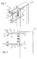
- FIGURE 1 is a perspective view of a beam connected to a column by a lateral bracing system according to an embodiment of the present invention.
- FIGURE 2 is a front view of the lateral bracing system according to Fig. 1 .
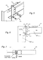
- FIGURES 3-5 are perspective views of a beam connected to a column by a lateral bracing system according to a further embodiment of the present invention.
- FIGURE 6 is a front view of the lateral bracing system shown in Figs. 3-5 .
- FIGURE 7 is a top view of the lateral bracing system shown in Figs. 3-5 .
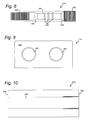
- FIGURE 8 is a side view of a yield link of the lateral bracing system shown in Figs. 3-5 .
- FIGURE 9 is an end view of a buckling restraint block of the lateral bracing system shown in Figs. 3-5 .
- FIGURE 10 is a side view of a buckling restraint block of the lateral bracing system shown in Figs. 3-5 .
- FIGURE 11 is a side view of a yield link according to an alternative embodiment of the present invention.
- FIGURE 12 is a side view of a buckling restraint block according to an alternative embodiment of the present invention.
- FIGURE 13 is a graph of lateral load vs. lateral displacement of the frame for embodiments of the present invention.
- Figs. 1 through 13 which in embodiments of the invention relate to a lateral bracing system having high initial stiffness and including yield links capable of effectively dissipating energy generated within the lateral bracing system under lateral loads.
- the present invention may be embodied in many different forms and should not be construed as being limited to the embodiments set forth herein. Rather these embodiments are provided so that this disclosure will be thorough and complete and will fully convey the invention to those skilled in the art. Indeed, the invention is intended to cover alternatives, modifications and equivalents of these embodiments, which are included within the scope and spirit of the invention as defined by the appended claims.
- numerous specific details are set forth in order to provide a thorough understanding of the present invention. However, it will be clear to those of ordinary skill in the art that the present invention may be practiced without such specific details.
- a frame 100 comprised in part of a horizontal beam 102 affixed to a vertical column 104.
- Each of the beam 102 and column 104 includes an opposed pair of flanges connected by a central diaphragm.
- the beam 102 is affixed to the column 104 by means of a beam stub 110 including a lateral bracing system.
- the lateral bracing system is comprised of a pair of buckling-restrained braced devices 112, one on each of the top and bottom flanges of beam stub 110.
- Each buckling-restrained braced device 112 includes a flat, "dog-bone” shaped yield link 114 welded or glued at its first end to a flange of the beam stub 110 and welded or glued at its second end to a flange of the column 104 ("dog bone” shaped in that it is narrower at a center portion than at its end portions).
- Covering the center portion of each yield link 114 is a buckling restraint block 116.
- Blocks 116 are welded or glued to the respective flanges of the beam stub 110.
- a shear tab 122 may further be provided between the beam stub 110 and column 104.
- the shear tab 122 may be affixed as by welding, gluing or bolting to a flange of column 104 and as by welding, gluing or bolting to the central diaphragm of beam stub 110.
- the beam stub 110 additionally includes an end plate 124 welded at an end of the beam stub opposite shear tab 122. End plate 124 may be bolted to a similar end plate 126 to affix the beam 102 to the beam stub 110 as explained hereinafter.
- the pair of buckling-restrained braced devices 112 operate in tandem to oppose rotation of the beam relative to the column (i.e. , rotation about the shear tab 122) under a lateral load. Attempted rotation in a first direction will place the first of the devices 112 in tension and the second of the devices in compression. Attempted rotation in the opposite direction will place the first of the devices in compression and the second in tension.
- the yield link 114 of the respective devices 112 provides high initial stiffness and tensile resistance to relative movement between the column 104 and the beam 102 under lateral loads, but provides stable yielding and energy dissipation under lateral loads above a predictable and controlled level.
- the bending strength of the column and beam could be designed to exceed the moment capacity of the yield links 114, and in particular, the thinner center portions of yield links 114.
- the yield links 114 yield under lateral loads before yielding or failure of the column or beam, and any damage is limited to the yield links which may be easily removed and replaced.
- the buckling restraint blocks 116 prevent buckling of the yield links under a compressive load.
- the shear tab 122 is provided to oppose vertical shear ( i.e. , along the length of column 104) under a vertical load.
- the lateral bracing system provided between beam 102 and column 104 as described with respect to the above and below embodiments allows the omission of the lateral-torsional buckling restraint system conventionally provided as part of the beam. That is, in prior art systems, a lateral-torsional buckling restraint system was provided as part of the beam to yield in the event of excessive lateral loads. These lateral-torsional buckling restraint systems include a yield link and lateral braces to prevent buckling of the beam. Through the use of the lateral bracing system according to the present invention, the lateral-torsional buckling restraint system found on the beam in the prior art may be omitted.
- the lateral bracing system of the present invention Having the ability to control, via a finite cap to the link moment capacity, the input demands on the beam through the lateral bracing system of the present invention, that is separate from the beam itself, allows the beam to be designed without bracing. It also allows the beams and columns to be designed to remain elastic at the level of ultimate yield-link connection moment capacity.
- continuity plates 130 may optionally be affixed to the affected flange of column 104 to oppose the forces exerted by the yield links.
- the assembly and connection of beam 102 and column 104 may be accomplished as follows.
- the first end of the yield links 114 and the buckling-restraint blocks 116 may be welded or glued to the beam stub 110.
- the end plate 124 may also be welded or glued to the stub 110.
- the beam stub 110 may then be welded or glued to column 104 by welding/gluing the second end of the yield links 114 to the flange of column 104, and welding/gluing the shear tab to the diaphragm of column 104.
- the shear tab may then be bolted to the diaphragm of the beam stub 110.
- the joined beam stub 110 and column 104 may then be delivered to the worksite.
- the inclusion of beam stub 110 allows all welding/gluing to take place before the column arrives at the worksite.
- the end plate 126 may be welded or glued to the beam 102 and the beam may then be delivered to the worksite. Once at the worksite, the beam 102 may be affixed to the beam stub 110 by bolting the end plates 124 and 126 together.
- a lateral bracing system is provided which allows the omission of the beam stub 110 and provides a simpler yet effective design.
- a frame 200 is comprised in part of a horizontal beam 102 affixed to a vertical column 104. Although referred to as a vertical column and a horizontal beam, it is understood that the column and beam may be affixed to each other at angles other than 90° in alternative embodiments.
- the beam 102 is affixed to the column 104 by means of a lateral bracing system.
- the lateral bracing system is comprised of a pair of buckling-restrained braced devices 212, one on each of the top and bottom flanges of beam 102.
- Each buckling-restrained braced device 212 includes one or more cylindrical yield links 214, each including threads at its ends as explained hereinafter.
- Each set of one or more yield links 214 may be provided within a buckling restraint block 216 which is welded, glued or otherwise affixed to the upper and lower flanges of beam 102.
- a shear tab 222 may further be provided between the beam 102 and column 104.
- the shear tab 122 may be affixed as by welding, gluing or bolting to a flange of column 104 and as by welding, gluing or bolting to the central diaphragm of beam 102.
- Column flange stiffeners 230 may optionally be affixed to the flange of column 104 to oppose the forces exerted by the yield links.
- Fig. 8 shows a side view of an embodiment of a cylindrical yield link 214 and Figs. 9 and 10 show end and side views, respectively, of an embodiment of a buckling restraint block 216.
- Cylindrical yield link 214 may be formed of steel and includes first and second threaded ends 240, 242, and a center portion 244 between ends 240 and 242. Center portion 244 preferably has a smaller diameter than ends 240, 242 so that, upon yielding as explained hereinafter, the yield link 214 yields at center portion 244.
- Tapered sections 246 and 248 may be provided to smoothly transition from the diameter of ends 240, 242 to center portion 244.
- ends 240 and 242 may be chamfered to allow easy insertion into the buckling restraint block 216.
- Center portion 244 may include ribs 250, the purpose of which is explained hereinafter. It may be possible to form center portion 244 of a different material than ends 240 and 242, where the center portion has a lower modulus of elasticity. In such an embodiment, the center portion may be provided with the same diameter as end 240, and still be the first portion to yield ,upon tensile stresses above the center portion yield point.
- end 242 may have a larger diameter than end 240.
- end 242 may have a diameter of 1.30 inches
- end 240 may have a diameter of 1.25 inches
- center portion 244 may have a diameter of 1.00 inch, except at ribs 250, which may have a diameter of 1.25 inches. It is understood that each of the above dimensions may vary above and below that set forth, either proportionately or disproportionately to each other, in alternative embodiments.
- Buckling restraint block 216 may be a block of metal such as aluminum or steel with one or more bores 260 formed therethrough for receiving the one or more yield links 214.
- Bores 260 may have a diameter which is approximately the same as the diameter of ribs 250 and/or end 240, with the end 264 being slightly larger to receive threaded end 242 of yield links 214.
- the length (along the length of beam 102) of block 216 may for example be 6.50 inches, the width (across the width of the flanges of beam 102) may be approximately equal to or slightly less than the width of the flanges of beam 102, such as for example 7.00 inches, and the block 216 may have a height of 2.50 inches.
- the bores may be spaced from each other 4.00 inches, centerline to centerline. It is understood that each of these dimensions may vary, either proportionately or disproportionately to each other, in alternative embodiments.
- the block 216 may include an end 262, through which end 240 of yield link 214 protrudes when the device 112 is assembled as explained below, and an end 264 opposite end 262. A portion of bores 260 may be threaded adjacent end 264, for receiving threaded end 242 of the yield link as explained below.
- Beam 102 may be delivered to the worksite having block 216 welded, glued or otherwise affixed thereto.
- Column may be delivered to the worksite having shear tab 222 welded, glued or otherwise affixed thereto.
- yield links 214 may be inserted into bores 260, with end 240 of yield link 214 inserted first into end 264 of block 216 ( i.e. , right to left from the perspective of Figs. 6 and 7 ).
- the smaller diameter portions 240, 244 and 250 of the yield link pass through the larger diameter bore 260 until threaded yield link end 242 engages the threaded end of the bore.
- end 242 may be threaded into block end 264 to affix the yield link 214 to the buckling restraint block 216.
- the end 242 of yield link 214 may include a head to drive the link into the block, but the head may be omitted in alternative embodiments.
- the link is screwed in until link end 240 protrudes from block end 262.
- a nut 270 is then threaded onto link end 240, the end 240 passes through a hole formed in the flange of column 104, and a second nut 272 is threaded onto end 240.
- nuts 270 and 272 are tightened down on opposed sides of the column flange, the buckling-restrained braced device 212 is fixed in position to oppose movement between beam 102 and column 104.
- the pair of buckling-restrained braced devices 212 operate in tandem to oppose rotation of the beam 102 relative to the column 104 under a lateral load.
- the yield link 214 of the respective devices 212 provides high initial stiffness and tensile resistance to relative movement between the column 104 and the beam 102 under lateral loads, but provides stable yielding at center portion 244 and energy dissipation under lateral loads above a predictable and controlled level.
- bending strength of the column and beam could be designed to exceed the moment capacity of portions 244 of yield links 214.
- the yield links 214 yield under lateral loads before yielding or failure of the column or beam, and any damage is limited to the yield links which may be easily removed and replaced.
- the buckling-restraint blocks 216 prevent buckling of the yield links under a compressive load.
- the relative diameter of bore 260 to the diameter of the center portion 244 of the yield links 214 limits the amount which the yield links may buckle.
- the center portion 244 may include ribs 250.
- the enlarged diameter of ribs 250 further limit the amount to which the yield links 214 may buckle within bore 260 of buckling restraint block 216.
- ribs 250 may be omitted altogether.
- the link end 242 has a greater diameter than link end 240, thereby allowing the yield link to pass freely through the buckling restraint block 216 until engagement of the threads in link end 242 and block end 264.
- the yield link 214 has ends 240 and 242 with equal diameters, for example 1.25 inches.
- the block 216 may have a bore 260 threaded along its entire length as shown in Fig. 12 .
- the embodiment of Figs. 11 and 12 may operate with or without ribs in the smaller diameter center portion.
- the lateral bracing system has sufficient stiffness and rigidity to provide a high degree of resistance to deflection under applied lateral loads.
- the structure of the present invention provides for stable yielding of the yield links. In this way, the applied lateral loads are hysteretically dampened from the system, and a high degree of energy is dissipated, thereby preventing damage to the frame. Moreover, the energy dissipation and stable yielding of the yield links allow the frame 100 to withstand repeated deflection under lateral loads without failure.
- the lateral bracing system may be restored to its virgin integrity and load bearing capabilities simply by removing and replacing the yield links.
- the structural frame remains intact and need not be replaced.
- Fig. 13 is a plot of the response of an embodiment of the buckling-restrained braced device 112 of Figs. 1 through 2 and an embodiment of the buckling-restrained braced device 212 of Figs. 3 through 10 for applied lateral loads. As seen, both embodiments perform elastically until their yield point at about 22,000 lbs. lateral load.
Landscapes
- Engineering & Computer Science (AREA)
- Architecture (AREA)
- Environmental & Geological Engineering (AREA)
- Civil Engineering (AREA)
- Structural Engineering (AREA)
- Business, Economics & Management (AREA)
- Emergency Management (AREA)
- Physics & Mathematics (AREA)
- Electromagnetism (AREA)
- Joining Of Building Structures In Genera (AREA)
- Buildings Adapted To Withstand Abnormal External Influences (AREA)
Applications Claiming Priority (2)
| Application Number | Priority Date | Filing Date | Title |
|---|---|---|---|
| US87158706P | 2006-12-22 | 2006-12-22 | |
| US11/959,696 US20080148681A1 (en) | 2006-12-22 | 2007-12-19 | Moment frame connector |
Publications (3)
| Publication Number | Publication Date |
|---|---|
| EP1936053A2 true EP1936053A2 (fr) | 2008-06-25 |
| EP1936053A3 EP1936053A3 (fr) | 2011-06-22 |
| EP1936053B1 EP1936053B1 (fr) | 2016-03-02 |
Family
ID=39203187
Family Applications (1)
| Application Number | Title | Priority Date | Filing Date |
|---|---|---|---|
| EP07255025.4A Active EP1936053B1 (fr) | 2006-12-22 | 2007-12-21 | Connecteur de trame de moment |
Country Status (7)
| Country | Link |
|---|---|
| US (2) | US20080148681A1 (fr) |
| EP (1) | EP1936053B1 (fr) |
| JP (1) | JP5398980B2 (fr) |
| KR (1) | KR101460258B1 (fr) |
| CN (1) | CN101343894B (fr) |
| AU (1) | AU2007254648B2 (fr) |
| CA (1) | CA2616474C (fr) |
Cited By (3)
| Publication number | Priority date | Publication date | Assignee | Title |
|---|---|---|---|---|
| ITRM20090013A1 (it) * | 2009-01-16 | 2010-07-17 | Tis Tech Idraulico Stradali | Sistema a portale per la realizzazione di dispositivi per la dissipazione di energia particolarmente adatto per la protezione sismica delle strutture |
| EP2468986A3 (fr) * | 2010-12-14 | 2015-07-15 | Simpson Strong-Tie Company, Inc. | Connecteur de trame de moment |
| US11299880B2 (en) | 2006-12-22 | 2022-04-12 | Simpson Strong-Tie Company Inc. | Moment frame connector |
Families Citing this family (29)
| Publication number | Priority date | Publication date | Assignee | Title |
|---|---|---|---|---|
| US8001734B2 (en) * | 2004-05-18 | 2011-08-23 | Simpson Strong-Tie Co., Inc. | Moment frame links wall |
| EP2447446A1 (fr) * | 2010-10-28 | 2012-05-02 | Sika Technology AG | Ancrage terminal d'éléments de traction sur des supports en béton armé |
| CN102251582B (zh) * | 2011-05-16 | 2013-08-21 | 北京国泰建设集团有限公司 | 高低连体建筑无障碍装修结构及其施工方法 |
| CN102758499B (zh) * | 2012-07-05 | 2015-01-07 | 北京工业大学 | 一种震后可恢复功能的预制预应力钢梁 |
| US9506239B2 (en) | 2012-11-30 | 2016-11-29 | Mitek Holdings, Inc. | Gusset plate connection in bearing of beam to column |
| CA2898340C (fr) * | 2012-11-30 | 2018-02-13 | Mitek Holdings, Inc. | Connexion de plaques gousset d'une poutre a une colonne |
| EP2886748A1 (fr) * | 2013-12-20 | 2015-06-24 | Siniat International SAS | Structure de protection pour partitions de panneaux |
| CN104234206A (zh) * | 2014-08-27 | 2014-12-24 | 浙江精工钢结构集团有限公司 | 一种钢结构钢梁免拆卸连接板装置 |
| US10450748B2 (en) | 2014-08-29 | 2019-10-22 | University Of Utah Research Foundation | Structural braces and related methods |
| SI3212861T1 (sl) | 2014-09-26 | 2019-05-31 | Universita' Degli Studi Di Padova | Disipativna povezava z optimizirano trdoto in trdnostjo za povezovanje gradbenih elementov |
| CN104452961A (zh) * | 2014-12-08 | 2015-03-25 | 上海应用技术学院 | 村镇低层装配式减震建筑结构体系 |
| US9464427B2 (en) * | 2015-01-23 | 2016-10-11 | Columbia Insurance Company | Light gauge steel beam-to-column joint with yielding panel zone |
| MX368074B (es) | 2015-01-23 | 2019-09-17 | Mitek Holdings Inc | Montaje de panel aislado. |
| CN104847019A (zh) * | 2015-01-26 | 2015-08-19 | 祝磊 | 采用法兰连接的钢框架结构 |
| CN104831813B (zh) * | 2015-05-12 | 2016-11-30 | 烟台金田科技有限公司 | 模块智能抗震保温一体组装结构房屋 |
| US20160356033A1 (en) | 2015-06-03 | 2016-12-08 | Mitek Holdings, Inc | Gusset plate connection of braced beam to column |
| AU2016200130B2 (en) * | 2016-01-08 | 2021-04-01 | Auvenco Pty Ltd | Composite structural member for a building structure |
| US20170314254A1 (en) | 2016-05-02 | 2017-11-02 | Mitek Holdings, Inc. | Moment resisting bi-axial beam-to-column joint connection |
| JP6823950B2 (ja) * | 2016-07-01 | 2021-02-03 | センクシア株式会社 | 柱と梁との接合構造および接合方法 |
| US10179991B2 (en) | 2016-10-03 | 2019-01-15 | Mitek Holdings, Inc. | Forming column assemblies for moment resisting bi-axial beam-to-column joint connections |
| US11236502B2 (en) | 2016-10-03 | 2022-02-01 | Mitek Holdings, Inc. | Gusset plate and column assembly for moment resisting bi-axial beam-to-column joint connections |
| US10982710B2 (en) | 2017-04-13 | 2021-04-20 | Hamilton Sundstrand Corporation | Shaft disconnects |
| US10533338B2 (en) | 2017-05-11 | 2020-01-14 | Katerra, Inc. | Connector for use in inter-panel connection between shear wall elements |
| BR112020006721A2 (pt) | 2017-10-03 | 2020-10-06 | Patco Llc | conector de cedência sísmica, painel de cedência sísmica, e, método para conectar um painel de cedência sísmica a uma coluna estrutural utilizando um conector de cedência sísmica. |
| US12270227B2 (en) | 2019-09-26 | 2025-04-08 | Christopher ABELA | Ductile anchor attachment (DAA) mechanism, fuse plate system, and modified jacket |
| US11499331B2 (en) | 2019-09-26 | 2022-11-15 | Christopher ABELA | Ductile anchor attachment (DAA) mechanism |
| CN111259549B (zh) * | 2020-01-16 | 2022-02-15 | 中南大学 | 一种任意边界条件下板组合结构屈曲分析的半解析方法 |
| CN116290440B (zh) * | 2023-03-13 | 2025-04-25 | 中国铁建大桥工程局集团有限公司 | 一种用于钢结构建筑的装配式连接件 |
| US12091879B1 (en) * | 2024-03-12 | 2024-09-17 | King Saud University | Beam-column moment connection structure |
Citations (1)
| Publication number | Priority date | Publication date | Assignee | Title |
|---|---|---|---|---|
| US20050257451A1 (en) | 2004-05-18 | 2005-11-24 | Pryor Steven E | Moment frame links wall |
Family Cites Families (55)
| Publication number | Priority date | Publication date | Assignee | Title |
|---|---|---|---|---|
| US1744600A (en) * | 1927-07-12 | 1930-01-21 | Albert J Wilcox | Beam and column connection |
| US3173522A (en) * | 1961-11-15 | 1965-03-16 | Zimmer Frantisek | Joints |
| US3674289A (en) * | 1969-05-20 | 1972-07-04 | Ger Bro Corp | Tri-hedral clip for steel construction |
| US3716959A (en) * | 1970-09-15 | 1973-02-20 | J Bernardi | Beam end construction for semi-rigid connection to a column |
| US3716957A (en) * | 1970-10-23 | 1973-02-20 | J Bernardi | Column flange and stiffener plate construction |
| US3828516A (en) * | 1971-11-24 | 1974-08-13 | Wieland Werke Ag | Press-fitted joint between a transom bar and a frame or sash bar for use on windows, doors or the like |
| NL7313992A (fr) * | 1972-10-12 | 1974-04-16 | ||
| SE379087B (fr) * | 1973-07-27 | 1975-09-22 | A G Offenbroich | |
| GB1565178A (en) * | 1977-02-24 | 1980-04-16 | Interfix Ltd | Bone screw |
| US4192621A (en) * | 1978-09-26 | 1980-03-11 | Ab Gothenburg Motor | Method for interconnecting two shaft-ends and a shaft coupling made in accordance with said method |
| US4326826A (en) * | 1979-06-04 | 1982-04-27 | Pilgrim Engineering Developments Limited | Bolts and methods of bolting |
| US4463753A (en) * | 1980-01-04 | 1984-08-07 | Gustilo Ramon B | Compression bone screw |
| US4447217A (en) * | 1980-05-16 | 1984-05-08 | Stephen Blandford | Coupling with overload protection |
| US5048243A (en) * | 1988-03-11 | 1991-09-17 | Ward John D | Earthquake restraint mechanism |
| US5019079A (en) * | 1989-11-20 | 1991-05-28 | Zimmer, Inc. | Bone screw |
| JPH048945A (ja) * | 1990-04-27 | 1992-01-13 | Nkk Corp | 振動防止装置 |
| JPH0754405Y2 (ja) * | 1991-03-11 | 1995-12-18 | 清司 細川 | 木造建築材用締結金具と木造建築物の締結構造 |
| US6030162A (en) * | 1998-12-18 | 2000-02-29 | Acumed, Inc. | Axial tension screw |
| US6220410B1 (en) * | 1993-06-02 | 2001-04-24 | Damping Systems Limited | Damper |
| JP3301568B2 (ja) * | 1993-08-25 | 2002-07-15 | 林建設工業株式会社 | 建造物の施工方法 |
| US5490356A (en) * | 1993-11-24 | 1996-02-13 | Mm Systems Of Arizona | Seismic isolation bearing |
| JP2726003B2 (ja) * | 1994-06-10 | 1998-03-11 | 戸田建設株式会社 | 鉄骨梁における制振装置 |
| US5595040A (en) * | 1994-07-20 | 1997-01-21 | National Science Council | Beam-to-column connection |
| IT1269140B (it) * | 1994-08-19 | 1997-03-21 | Gregorio Amore | Struttura portante metallica con nodi strutturali esenti da saldature e forature |
| US5536127A (en) * | 1994-10-13 | 1996-07-16 | Pennig; Dietmar | Headed screw construction for use in fixing the position of an intramedullary nail |
| US5660017A (en) * | 1994-12-13 | 1997-08-26 | Houghton; David L. | Steel moment resisting frame beam-to-column connections |
| US5813181A (en) * | 1995-08-21 | 1998-09-29 | Ashton; Roger Wall | Continuity tie |
| US6073405A (en) * | 1995-12-22 | 2000-06-13 | Icf Kaiser Engineers, Inc. | Fitting for effecting bolted connection between a beam and a column in a steel frame structure |
| US6059482A (en) * | 1997-01-22 | 2000-05-09 | Icf Kaiser Engineering, Inc. | Bolted connector for connecting beams to columns |
| US6474902B1 (en) * | 1997-01-22 | 2002-11-05 | Icf Kaiser Engineers, Inc. | Connector for connecting beams to columns |
| JPH10306498A (ja) | 1997-04-30 | 1998-11-17 | Sumitomo Metal Ind Ltd | 座屈拘束ブレース |
| JP3076539B2 (ja) * | 1997-08-25 | 2000-08-14 | 株式会社アルテス | 閉鎖形断面柱と梁の接合構造 |
| US5956916A (en) * | 1997-10-30 | 1999-09-28 | Steel Floors, Llc | Shear tab method and apparatus |
| JP2000027293A (ja) | 1998-07-14 | 2000-01-25 | Sumitomo Metal Ind Ltd | 座屈拘束ブレース |
| US6007267A (en) * | 1998-07-16 | 1999-12-28 | Kenneth Roberts | Mechanical load fuse assembly |
| US6138427A (en) * | 1998-08-28 | 2000-10-31 | Houghton; David L. | Moment resisting, beam-to-column connection |
| JP3858480B2 (ja) * | 1998-11-05 | 2006-12-13 | Jfeスチール株式会社 | スプライスプレート及び梁継ぎ手構造 |
| US6516583B1 (en) * | 1999-03-26 | 2003-02-11 | David L. Houghton | Gusset plate connections for structural braced systems |
| US7497054B2 (en) * | 2001-06-06 | 2009-03-03 | Nippon Steel Corporation | Column-and-beam join structure |
| US6739099B2 (en) * | 2001-06-06 | 2004-05-25 | Nippon Steel Corporation | Column-and-beam join structure |
| US6591573B2 (en) * | 2001-07-12 | 2003-07-15 | David L. Houghton | Gusset plates connection of beam to column |
| US20030230032A1 (en) * | 2002-06-13 | 2003-12-18 | George Shahnazarian | Take-up devices for use in building structure |
| US6739568B2 (en) * | 2002-10-25 | 2004-05-25 | Unisorb, Inc. | Apparatus for isolating and leveling a machine foundation |
| JP4376088B2 (ja) | 2003-02-28 | 2009-12-02 | 新日本製鐵株式会社 | 梁継手構造 |
| JP4116943B2 (ja) | 2003-07-28 | 2008-07-09 | 新日本製鐵株式会社 | 柱と梁の接合構造 |
| JP2005213964A (ja) | 2004-02-02 | 2005-08-11 | Nippon Steel Corp | 柱脚部と上部部材の制振接合構造 |
| TWI262229B (en) * | 2004-02-02 | 2006-09-21 | Chong-Shien Tsai | Multi-section earthquake protection device |
| US7178296B2 (en) * | 2004-03-19 | 2007-02-20 | Houghton David L | Structural joint connection providing blast resistance and a beam-to-beam connection resistant to moments, tension and torsion across a column |
| US20050257490A1 (en) * | 2004-05-18 | 2005-11-24 | Pryor Steven E | Buckling restrained braced frame |
| JP2005350906A (ja) | 2004-06-09 | 2005-12-22 | Nippon Steel Corp | 柱梁の接合構造 |
| JP4805619B2 (ja) * | 2005-07-06 | 2011-11-02 | 高周波熱錬株式会社 | ダンパーシステム |
| JP2007032802A (ja) * | 2005-07-29 | 2007-02-08 | Meidensha Corp | セラミックス螺子体とその製造方法 |
| JP4203533B1 (ja) * | 2008-03-05 | 2009-01-07 | 株式会社アイ.テック | 鉄骨柱及び鉄骨梁の接合構造 |
| US8146322B2 (en) * | 2008-08-21 | 2012-04-03 | Mitek Holdings, Inc. | Building structure, method of making, and components |
| US20110232221A1 (en) * | 2010-03-25 | 2011-09-29 | National Applied Research Laboratories | Buckling restrained brace |
-
2007
- 2007-12-19 US US11/959,696 patent/US20080148681A1/en not_active Abandoned
- 2007-12-21 CN CN200710301531.4A patent/CN101343894B/zh active Active
- 2007-12-21 CA CA2616474A patent/CA2616474C/fr active Active
- 2007-12-21 AU AU2007254648A patent/AU2007254648B2/en active Active
- 2007-12-21 EP EP07255025.4A patent/EP1936053B1/fr active Active
- 2007-12-24 KR KR1020070136829A patent/KR101460258B1/ko active Active
- 2007-12-25 JP JP2007341933A patent/JP5398980B2/ja active Active
-
2011
- 2011-04-06 US US13/081,410 patent/US8375652B2/en active Active
Patent Citations (1)
| Publication number | Priority date | Publication date | Assignee | Title |
|---|---|---|---|---|
| US20050257451A1 (en) | 2004-05-18 | 2005-11-24 | Pryor Steven E | Moment frame links wall |
Cited By (4)
| Publication number | Priority date | Publication date | Assignee | Title |
|---|---|---|---|---|
| US11299880B2 (en) | 2006-12-22 | 2022-04-12 | Simpson Strong-Tie Company Inc. | Moment frame connector |
| ITRM20090013A1 (it) * | 2009-01-16 | 2010-07-17 | Tis Tech Idraulico Stradali | Sistema a portale per la realizzazione di dispositivi per la dissipazione di energia particolarmente adatto per la protezione sismica delle strutture |
| EP2468986A3 (fr) * | 2010-12-14 | 2015-07-15 | Simpson Strong-Tie Company, Inc. | Connecteur de trame de moment |
| AU2021229119B2 (en) * | 2010-12-14 | 2023-11-09 | Simpson Strong-Tie Company | Moment frame connector |
Also Published As
| Publication number | Publication date |
|---|---|
| JP2008157020A (ja) | 2008-07-10 |
| US8375652B2 (en) | 2013-02-19 |
| US20080148681A1 (en) | 2008-06-26 |
| CA2616474C (fr) | 2016-02-23 |
| CN101343894A (zh) | 2009-01-14 |
| AU2007254648A1 (en) | 2008-07-10 |
| EP1936053A3 (fr) | 2011-06-22 |
| AU2007254648B2 (en) | 2014-09-11 |
| CN101343894B (zh) | 2014-01-15 |
| EP1936053B1 (fr) | 2016-03-02 |
| US20110179725A1 (en) | 2011-07-28 |
| JP5398980B2 (ja) | 2014-01-29 |
| KR101460258B1 (ko) | 2014-11-10 |
| CA2616474A1 (fr) | 2008-06-22 |
| KR20080059107A (ko) | 2008-06-26 |
Similar Documents
| Publication | Publication Date | Title |
|---|---|---|
| EP1936053B1 (fr) | Connecteur de trame de moment | |
| AU2021229119B2 (en) | Moment frame connector | |
| US11299880B2 (en) | Moment frame connector | |
| US11162260B2 (en) | Moment frame including lateral bracing system and coped beam | |
| US20050204684A1 (en) | Structural joint connection providing blast resistance and a beam-to-beam connection resistant to moments, tension and torsion across a column | |
| US20140259993A1 (en) | Structural connection mechanisms for providing discontinuous elastic behavior in structural framing systems | |
| US12359420B2 (en) | Structural fuses and connection systems including the same | |
| US20160265217A1 (en) | Structural connection mechanisms for providing discontinuous elastic behavior in structural framing systems | |
| KR101344813B1 (ko) | 기둥-보 접합구조물 및 접합방법 | |
| US11987972B2 (en) | Moment frame for a sloped roof construction | |
| AU2014274605B2 (en) | A construction and a method of assembling a frame having a beam, column and lateral bracing system therebetween | |
| NZ775314B2 (en) | Moment frame including lateral bracing system and coped beam | |
| WO2022178148A1 (fr) | Cadre de moment pour une construction de toiture inclinée |
Legal Events
| Date | Code | Title | Description |
|---|---|---|---|
| PUAI | Public reference made under article 153(3) epc to a published international application that has entered the european phase |
Free format text: ORIGINAL CODE: 0009012 |
|
| AK | Designated contracting states |
Kind code of ref document: A2 Designated state(s): AT BE BG CH CY CZ DE DK EE ES FI FR GB GR HU IE IS IT LI LT LU LV MC MT NL PL PT RO SE SI SK TR |
|
| AX | Request for extension of the european patent |
Extension state: AL BA HR MK RS |
|
| PUAL | Search report despatched |
Free format text: ORIGINAL CODE: 0009013 |
|
| AK | Designated contracting states |
Kind code of ref document: A3 Designated state(s): AT BE BG CH CY CZ DE DK EE ES FI FR GB GR HU IE IS IT LI LT LU LV MC MT NL PL PT RO SE SI SK TR |
|
| AX | Request for extension of the european patent |
Extension state: AL BA HR MK RS |
|
| RIC1 | Information provided on ipc code assigned before grant |
Ipc: E04B 1/28 20060101ALI20110517BHEP Ipc: E04H 9/02 20060101ALI20110517BHEP Ipc: E04B 1/24 20060101AFI20080331BHEP |
|
| 17P | Request for examination filed |
Effective date: 20111222 |
|
| AKX | Designation fees paid |
Designated state(s): AT BE BG CH CY CZ DE DK EE ES FI FR GB GR HU IE IS IT LI LT LU LV MC MT NL PL PT RO SE SI SK TR |
|
| GRAP | Despatch of communication of intention to grant a patent |
Free format text: ORIGINAL CODE: EPIDOSNIGR1 |
|
| RIC1 | Information provided on ipc code assigned before grant |
Ipc: E04B 1/24 20060101AFI20150317BHEP Ipc: E04H 9/02 20060101ALI20150317BHEP Ipc: E04B 1/28 20060101ALI20150317BHEP |
|
| INTG | Intention to grant announced |
Effective date: 20150408 |
|
| GRAS | Grant fee paid |
Free format text: ORIGINAL CODE: EPIDOSNIGR3 |
|
| GRAA | (expected) grant |
Free format text: ORIGINAL CODE: 0009210 |
|
| AK | Designated contracting states |
Kind code of ref document: B1 Designated state(s): AT BE BG CH CY CZ DE DK EE ES FI FR GB GR HU IE IS IT LI LT LU LV MC MT NL PL PT RO SE SI SK TR |
|
| REG | Reference to a national code |
Ref country code: GB Ref legal event code: FG4D |
|
| REG | Reference to a national code |
Ref country code: AT Ref legal event code: REF Ref document number: 778174 Country of ref document: AT Kind code of ref document: T Effective date: 20160315 Ref country code: CH Ref legal event code: EP |
|
| REG | Reference to a national code |
Ref country code: IE Ref legal event code: FG4D |
|
| REG | Reference to a national code |
Ref country code: DE Ref legal event code: R096 Ref document number: 602007045026 Country of ref document: DE |
|
| REG | Reference to a national code |
Ref country code: NL Ref legal event code: MP Effective date: 20160302 |
|
| REG | Reference to a national code |
Ref country code: LT Ref legal event code: MG4D |
|
| REG | Reference to a national code |
Ref country code: AT Ref legal event code: MK05 Ref document number: 778174 Country of ref document: AT Kind code of ref document: T Effective date: 20160302 |
|
| PG25 | Lapsed in a contracting state [announced via postgrant information from national office to epo] |
Ref country code: ES Free format text: LAPSE BECAUSE OF FAILURE TO SUBMIT A TRANSLATION OF THE DESCRIPTION OR TO PAY THE FEE WITHIN THE PRESCRIBED TIME-LIMIT Effective date: 20160302 Ref country code: GR Free format text: LAPSE BECAUSE OF FAILURE TO SUBMIT A TRANSLATION OF THE DESCRIPTION OR TO PAY THE FEE WITHIN THE PRESCRIBED TIME-LIMIT Effective date: 20160603 Ref country code: FI Free format text: LAPSE BECAUSE OF FAILURE TO SUBMIT A TRANSLATION OF THE DESCRIPTION OR TO PAY THE FEE WITHIN THE PRESCRIBED TIME-LIMIT Effective date: 20160302 |
|
| PG25 | Lapsed in a contracting state [announced via postgrant information from national office to epo] |
Ref country code: AT Free format text: LAPSE BECAUSE OF FAILURE TO SUBMIT A TRANSLATION OF THE DESCRIPTION OR TO PAY THE FEE WITHIN THE PRESCRIBED TIME-LIMIT Effective date: 20160302 Ref country code: LT Free format text: LAPSE BECAUSE OF FAILURE TO SUBMIT A TRANSLATION OF THE DESCRIPTION OR TO PAY THE FEE WITHIN THE PRESCRIBED TIME-LIMIT Effective date: 20160302 Ref country code: LV Free format text: LAPSE BECAUSE OF FAILURE TO SUBMIT A TRANSLATION OF THE DESCRIPTION OR TO PAY THE FEE WITHIN THE PRESCRIBED TIME-LIMIT Effective date: 20160302 Ref country code: SE Free format text: LAPSE BECAUSE OF FAILURE TO SUBMIT A TRANSLATION OF THE DESCRIPTION OR TO PAY THE FEE WITHIN THE PRESCRIBED TIME-LIMIT Effective date: 20160302 Ref country code: NL Free format text: LAPSE BECAUSE OF FAILURE TO SUBMIT A TRANSLATION OF THE DESCRIPTION OR TO PAY THE FEE WITHIN THE PRESCRIBED TIME-LIMIT Effective date: 20160302 Ref country code: PL Free format text: LAPSE BECAUSE OF FAILURE TO SUBMIT A TRANSLATION OF THE DESCRIPTION OR TO PAY THE FEE WITHIN THE PRESCRIBED TIME-LIMIT Effective date: 20160302 |
|
| PG25 | Lapsed in a contracting state [announced via postgrant information from national office to epo] |
Ref country code: EE Free format text: LAPSE BECAUSE OF FAILURE TO SUBMIT A TRANSLATION OF THE DESCRIPTION OR TO PAY THE FEE WITHIN THE PRESCRIBED TIME-LIMIT Effective date: 20160302 Ref country code: IS Free format text: LAPSE BECAUSE OF FAILURE TO SUBMIT A TRANSLATION OF THE DESCRIPTION OR TO PAY THE FEE WITHIN THE PRESCRIBED TIME-LIMIT Effective date: 20160702 |
|
| PG25 | Lapsed in a contracting state [announced via postgrant information from national office to epo] |
Ref country code: RO Free format text: LAPSE BECAUSE OF FAILURE TO SUBMIT A TRANSLATION OF THE DESCRIPTION OR TO PAY THE FEE WITHIN THE PRESCRIBED TIME-LIMIT Effective date: 20160302 Ref country code: PT Free format text: LAPSE BECAUSE OF FAILURE TO SUBMIT A TRANSLATION OF THE DESCRIPTION OR TO PAY THE FEE WITHIN THE PRESCRIBED TIME-LIMIT Effective date: 20160704 Ref country code: SK Free format text: LAPSE BECAUSE OF FAILURE TO SUBMIT A TRANSLATION OF THE DESCRIPTION OR TO PAY THE FEE WITHIN THE PRESCRIBED TIME-LIMIT Effective date: 20160302 Ref country code: CZ Free format text: LAPSE BECAUSE OF FAILURE TO SUBMIT A TRANSLATION OF THE DESCRIPTION OR TO PAY THE FEE WITHIN THE PRESCRIBED TIME-LIMIT Effective date: 20160302 |
|
| REG | Reference to a national code |
Ref country code: DE Ref legal event code: R097 Ref document number: 602007045026 Country of ref document: DE |
|
| PG25 | Lapsed in a contracting state [announced via postgrant information from national office to epo] |
Ref country code: IT Free format text: LAPSE BECAUSE OF FAILURE TO SUBMIT A TRANSLATION OF THE DESCRIPTION OR TO PAY THE FEE WITHIN THE PRESCRIBED TIME-LIMIT Effective date: 20160302 Ref country code: BE Free format text: LAPSE BECAUSE OF FAILURE TO SUBMIT A TRANSLATION OF THE DESCRIPTION OR TO PAY THE FEE WITHIN THE PRESCRIBED TIME-LIMIT Effective date: 20160302 |
|
| PLBE | No opposition filed within time limit |
Free format text: ORIGINAL CODE: 0009261 |
|
| STAA | Information on the status of an ep patent application or granted ep patent |
Free format text: STATUS: NO OPPOSITION FILED WITHIN TIME LIMIT |
|
| REG | Reference to a national code |
Ref country code: FR Ref legal event code: PLFP Year of fee payment: 10 |
|
| PG25 | Lapsed in a contracting state [announced via postgrant information from national office to epo] |
Ref country code: DK Free format text: LAPSE BECAUSE OF FAILURE TO SUBMIT A TRANSLATION OF THE DESCRIPTION OR TO PAY THE FEE WITHIN THE PRESCRIBED TIME-LIMIT Effective date: 20160302 |
|
| 26N | No opposition filed |
Effective date: 20161205 |
|
| PG25 | Lapsed in a contracting state [announced via postgrant information from national office to epo] |
Ref country code: BG Free format text: LAPSE BECAUSE OF FAILURE TO SUBMIT A TRANSLATION OF THE DESCRIPTION OR TO PAY THE FEE WITHIN THE PRESCRIBED TIME-LIMIT Effective date: 20160602 Ref country code: SI Free format text: LAPSE BECAUSE OF FAILURE TO SUBMIT A TRANSLATION OF THE DESCRIPTION OR TO PAY THE FEE WITHIN THE PRESCRIBED TIME-LIMIT Effective date: 20160302 |
|
| REG | Reference to a national code |
Ref country code: CH Ref legal event code: PL |
|
| PG25 | Lapsed in a contracting state [announced via postgrant information from national office to epo] |
Ref country code: MC Free format text: LAPSE BECAUSE OF FAILURE TO SUBMIT A TRANSLATION OF THE DESCRIPTION OR TO PAY THE FEE WITHIN THE PRESCRIBED TIME-LIMIT Effective date: 20160302 |
|
| REG | Reference to a national code |
Ref country code: IE Ref legal event code: MM4A |
|
| PG25 | Lapsed in a contracting state [announced via postgrant information from national office to epo] |
Ref country code: CH Free format text: LAPSE BECAUSE OF NON-PAYMENT OF DUE FEES Effective date: 20161231 Ref country code: LI Free format text: LAPSE BECAUSE OF NON-PAYMENT OF DUE FEES Effective date: 20161231 Ref country code: LU Free format text: LAPSE BECAUSE OF NON-PAYMENT OF DUE FEES Effective date: 20161221 |
|
| PG25 | Lapsed in a contracting state [announced via postgrant information from national office to epo] |
Ref country code: IE Free format text: LAPSE BECAUSE OF NON-PAYMENT OF DUE FEES Effective date: 20161221 |
|
| REG | Reference to a national code |
Ref country code: FR Ref legal event code: PLFP Year of fee payment: 11 |
|
| PG25 | Lapsed in a contracting state [announced via postgrant information from national office to epo] |
Ref country code: HU Free format text: LAPSE BECAUSE OF FAILURE TO SUBMIT A TRANSLATION OF THE DESCRIPTION OR TO PAY THE FEE WITHIN THE PRESCRIBED TIME-LIMIT; INVALID AB INITIO Effective date: 20071221 Ref country code: CY Free format text: LAPSE BECAUSE OF FAILURE TO SUBMIT A TRANSLATION OF THE DESCRIPTION OR TO PAY THE FEE WITHIN THE PRESCRIBED TIME-LIMIT Effective date: 20160302 |
|
| PG25 | Lapsed in a contracting state [announced via postgrant information from national office to epo] |
Ref country code: TR Free format text: LAPSE BECAUSE OF FAILURE TO SUBMIT A TRANSLATION OF THE DESCRIPTION OR TO PAY THE FEE WITHIN THE PRESCRIBED TIME-LIMIT Effective date: 20160302 |
|
| REG | Reference to a national code |
Ref country code: FR Ref legal event code: PLFP Year of fee payment: 12 |
|
| PG25 | Lapsed in a contracting state [announced via postgrant information from national office to epo] |
Ref country code: MT Free format text: LAPSE BECAUSE OF NON-PAYMENT OF DUE FEES Effective date: 20161221 |
|
| REG | Reference to a national code |
Ref country code: DE Ref legal event code: R082 Ref document number: 602007045026 Country of ref document: DE |
|
| PGFP | Annual fee paid to national office [announced via postgrant information from national office to epo] |
Ref country code: DE Payment date: 20251119 Year of fee payment: 19 |
|
| PGFP | Annual fee paid to national office [announced via postgrant information from national office to epo] |
Ref country code: GB Payment date: 20251119 Year of fee payment: 19 |
|
| PGFP | Annual fee paid to national office [announced via postgrant information from national office to epo] |
Ref country code: FR Payment date: 20251119 Year of fee payment: 19 |