EP1936110A2 - Systèmes et procédés pour contrôler l'actionnement d'un composant de puits - Google Patents
Systèmes et procédés pour contrôler l'actionnement d'un composant de puits Download PDFInfo
- Publication number
- EP1936110A2 EP1936110A2 EP07023630A EP07023630A EP1936110A2 EP 1936110 A2 EP1936110 A2 EP 1936110A2 EP 07023630 A EP07023630 A EP 07023630A EP 07023630 A EP07023630 A EP 07023630A EP 1936110 A2 EP1936110 A2 EP 1936110A2
- Authority
- EP
- European Patent Office
- Prior art keywords
- deformable body
- well tool
- deforming member
- well
- resistance
- Prior art date
- Legal status (The legal status is an assumption and is not a legal conclusion. Google has not performed a legal analysis and makes no representation as to the accuracy of the status listed.)
- Granted
Links
Images


Classifications
-
- E—FIXED CONSTRUCTIONS
- E21—EARTH OR ROCK DRILLING; MINING
- E21B—EARTH OR ROCK DRILLING; OBTAINING OIL, GAS, WATER, SOLUBLE OR MELTABLE MATERIALS OR A SLURRY OF MINERALS FROM WELLS
- E21B43/00—Methods or apparatus for obtaining oil, gas, water, soluble or meltable materials or a slurry of minerals from wells
- E21B43/02—Subsoil filtering
- E21B43/10—Setting of casings, screens, liners or the like in wells
- E21B43/103—Setting of casings, screens, liners or the like in wells of expandable casings, screens, liners, or the like
-
- E—FIXED CONSTRUCTIONS
- E21—EARTH OR ROCK DRILLING; MINING
- E21B—EARTH OR ROCK DRILLING; OBTAINING OIL, GAS, WATER, SOLUBLE OR MELTABLE MATERIALS OR A SLURRY OF MINERALS FROM WELLS
- E21B43/00—Methods or apparatus for obtaining oil, gas, water, soluble or meltable materials or a slurry of minerals from wells
- E21B43/02—Subsoil filtering
- E21B43/10—Setting of casings, screens, liners or the like in wells
- E21B43/103—Setting of casings, screens, liners or the like in wells of expandable casings, screens, liners, or the like
- E21B43/105—Expanding tools specially adapted therefor
Definitions
- This invention relates to systems and methods for controlling actuation of a well component.
- a variety of well devices are actuated at downhole locations.
- packers, release subs, shock absorbers, and many other types of well tools are actuated while positioned in the wellbore.
- the actuation is accomplished by generating a force that acts on the well tool in a predetermined manner to transition the well tool from one state to another.
- the actuation force can be generated mechanically, hydraulically, or by other suitable energy sources.
- insufficient control over the actuating force can cause the well tool to be transitioned at an undesirable rate or in an undesirable manner.
- the present invention provides a system and method for controlling actuation of well components. Control is achieved by providing a constant resistance during actuation of the well tool.
- a resistance device is deployed in a tool string and connected to the subject well tool.
- the resistance device comprises a deformable body coupled with a deforming member that moves relative to the deformable body during actuation of the well tool. Resultant deformation provides the constant resistance and the consequent control over component actuation.
- the present invention relates to a system and methodology for facilitating the controlled actuation of a well component.
- the system and methodology enable the use of a resistance during actuation of a well component to improve transition of the well component from one state to another.
- a resistance device is connected within a well tool string and coupled to at least one well component able to undergo an actuation.
- the energy for actuation can be supplied mechanically, hydraulically, or by other suitable methods able to create a sufficient force to move a component or components of the well tool over a required distance for actuation.
- the resistance device is engaged to provide resistance to the actuating movement, thus controlling and improving component actuation in many applications.
- the well tool string and resistance device are moved into a wellbore to a specific location as desired for carrying out the well operation.
- the resistance device comprises a deformable body that is deformed in a controllable sequential manner. This localized deformation requires application of a constant force over a distance, thus requiring constant continuous work.
- Resistance devices can be designed, for example, to provide a constant crush resistance, an axial load, or impact energy absorption over a certain deformation length of the deformable body. This controlled resistance can be used with a variety of downhole well tools to improve tool functionality.
- a well tool string 20 is illustrated as deployed in a wellbore 22 that extends into, for example, a desired formation 24.
- wellbore 22 is lined with an appropriate liner or well casing 26.
- a deployment system 28, such as coiled tubing, is used to move a well completion or other well tools 30 downhole.
- the type of well tools, the number of well tools, and the arrangement of well tools in well tool string 20 may vary.
- deployment system 28 extends downwardly from a wellhead 31 and is coupled to a connector 32 used to connect the deployment system to a variety of other components.
- well tool string 20 comprises an actuatable well tool 34 that may be selectively actuated while at a downhole position in wellbore 22.
- Well tool 34 is coupled to an actuation control device, i.e. a resistance device, 36 in a manner that provides controlled resistance to actuation of well tool 34.
- well tool string 20 may comprise various other well tools 30 selected as desired for a specific well operation, e.g. a production operation and/or a well servicing operation.
- resistance device 36 can be used with many types of actuatable well tools 34.
- well tool 34 may comprise an inflatable packer, a controlled release sub, an energy absorber, e.g. shock absorber, or other well tools designed for actuation from one state to another while downhole.
- resistance device 36 comprises a deformable body that cooperates with a deforming member. As well tool 34 is actuated, relative movement occurs between the deforming member and the deformable body to deform the deformable body and thereby provide resistance to the actuating movement. Also, resistance device 36 can be designed to provide a relatively constant resistance which can be achieved by pre-work hardening the deformable body.
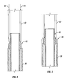
- pre-work hardening the deformable body is explained with reference to Figures 2 and 3 .
- a support fixture 38 is used to support a deforming member 40, and a deformable body 42 is brought into engagement with deforming member 40, as illustrated in Figure 2 .
- a force e.g. an axial force as indicated by arrows 44, is applied to deformable body 42 to pre-work harden deformable body 42 by sufficiently loading deformable body 42 to initiate deformation 46, as illustrated in Figure 3 .
- the load for pre-work hardening should be larger than the load required to expand the deformable body but smaller than the buckle load of the deformable body.
- Pre-work hardening of deformable body 42 creates a constant resistance as deformable body 42 is continually deformed by deforming member 40 during actuation of well tool 34.
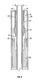
- resistance device 36 is created by the combination of deformable body 42 and deforming member 40, as illustrated in Figure 4 .
- the resistance device 36 is ready for installation into well tool string 20 in the preloaded state.
- deformable body 42 comprises a sleeve 48 that is generally tubular with a hollow interior 50.
- Deforming member 40 also is generally tubular and comprises an expander 52 combined with a mandrel 54 having a hollow interior 56.
- Hollow interiors 50, 56 provide a passageway that can be used for a variety of functions, including passage of fluids and/or routing of control lines, e.g. hydraulic lines, optical fibers, electrical wires and other conductors.
- control lines e.g. hydraulic lines, optical fibers, electrical wires and other conductors.
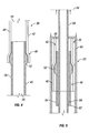
- the resistance device 36 can be connected into well tool string 20 under preload and coupled to actuatable well tool 34 by a suitable attachment member 58, as illustrated in Figure 5 .
- well tool 34 is coupled to deforming member 40 via attachment member 58 which is generally in the shape of a hollow tubular.
- attachment member 58 which is generally in the shape of a hollow tubular.
- expander 52 of deforming member 40 is pulled along the interior of deformable body 42.
- the movement of expander 52 deforms deformable body 42 and provides the desired resistance to actuation of well tool 34.
- deformable body 42 has been pre-work hardened which ensures a substantially constant resistance to the actuation force applied to well tool 34.
- the resistance remains substantially constant as expander 52 moves a stroke distance through deformable body 42 required for actuation.
- the deformable body 42 is held in place in well tool string 20 by an appropriate bracket or connector 60.
- attachment member 58 may comprise suitable attachment features 62 that cooperate with connector 60 to hold resistance device 36 under
- deformable body 42 is pulled along deforming member 40.
- deformable body 42 is formed as a sleeve, the sleeve is pulled across expander 52.
- connector 60 is attached to mandrel 54 by an appropriate attachment mechanism 64, and deformable body 42 is connected to a tensile member 66 by appropriate attachment mechanisms 68.
- tensile member 66 moves, it draws deformable body 42 across expander 52.
- tensile member 66 may be coupled to the actuatable well tool 34.
- resistance device 36 is designed to remain within the elastic limits of deformable body 42 during actuation of well tool 34. This allows resistance device 36 to be used repeatedly for multiple actuations of the well tool.
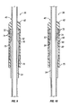
- One embodiment of a resistance device 36 that remains within the elastic limits of deformable body 42 is illustrated in Figures 7 and 8 .
- deformable body 42 comprises a sleeve 70 having a plurality of slots 72 separated by bars 74.
- the slots 72 and bars 74 facilitate or minimize the deformation of the sleeve. In other words, for the same amount of radial expansion, this design experiences less strain than one without slots 72.
- the design can be used in a manner that plastically deforms bars 74 during use, but the design is amenable to applications where it is desired to maintain deformable member 42 within its elastic limits.
- the embodiment of Figure 7 illustrates slots 72 and bars 74 arranged generally parallel and in an axial or longitudinal direction, however other arrangements of slots and bars can be used.
- the slots 72 are cut or otherwise formed in sleeve 70. Following insertion of deforming member 40 into the interior of sleeve 70, bars 74 are held in place by a cap 76.
- deforming member 40 can be moved back and forth along deformable body 42 to provide a desired resistance multiple times, as illustrated by the different positions of resistance device 36 in Figures 7 and 8 .
- deforming member 40 comprises expander 52 which expands bars 74 outwardly as it moves along sleeve 70, thus providing resistance.
- the outward expansion does not strain bars 74 and deformable member 42 beyond their elastic limits, thus enabling repeated and consistent resistance to movement as deforming member 40 and deformable body 42 are moved relative to each other.
- slots 72 can be made sufficiently longer than the stroke length, i.e. longer than the relative movement between deforming member 40 and deformable body 42.
- deformable body 42 is again formed as a sleeve 70 with slots 72 arranged in a generally axial direction and closed at both ends, as illustrated in Figure 9 .
- This type of deformable body 42 also can be designed to undergo elastic radial expansion without incurring plastic deformation.
- deforming member 40 is designed with expander 52 having a friction surface 78. Friction surface 78 may be formed as a roughened surface that creates additional resistive friction force to relative movement of deforming member 40 and deformable body 42. In one embodiment, friction surface 78 is created by a coating applied to the radially outer surface of expander 52 that slidingly engages the interior surface of bars 74.
- deforming member 40 comprises expander 52 constructed with more than one component.
- expander 52 may comprise a two-piece design having a center support region 80 and a ring 82 movably positioned on center support region 80.
- the ring 82 is movably mounted on a sloped surface or ramp 84 that slopes in a generally radially outward direction. Accordingly, as deforming member 40 moves in one direction relative to deformable body 42, ring 82 is forced radially outward to resist the force causing relative movement between deforming member 40 and deformable body 42. However, when relative movement between deforming member 40 and deformable body 42 occurs in the opposite direction, ring 82 slides down the ramp to reduce or eliminate the resistance to movement. Accordingly, this embodiment of resistance device 36 resists movement primarily in one direction.
- ring 82 may be formed as a split ring. Additionally, ring 82 may be provided with a friction coating 86 or other friction inducing surface to further resist movement along deformable body 42.
- resistance device 36 can again be designed such that deformable body 42 remains within its elastic limits as expander 52 moves along its interior. Additionally, deformable body 42 may again be designed with slots 72 separated by bars 74.
- deformable body 42 can be formed from metals, polymers, composite materials, fiber and/or particle reinforced composites, nano tube and/or nano fiber and/or nano particle reinforced composites, or other materials.
- deformable member 42 can be formed as a tubular or sleeve member, as a wall or parallel walls, or as a variety of other shapes designed to undergo deformation when moved relative to deforming member 40.
- deforming member 40 may have a variety of shapes and forms that are able to cooperate with and deform a particular embodiment of deformable body 42.
- deforming member 40 can be designed to move along an interior or an exterior of the deformable body.
- the material selection and/or the deformable body design can be used to establish a constant resistance.
- a deformable body 42 as illustrated in Figures 5 or 6 does not experience work hardening during deformation when constructed from certain materials, such as a fiber reinforced polymer composite material. This material selection effectively renders pre-work hardening of the deformable body 42 unnecessary while still providing a constant resistance over a distance.
Landscapes
- Geology (AREA)
- Life Sciences & Earth Sciences (AREA)
- Engineering & Computer Science (AREA)
- Mining & Mineral Resources (AREA)
- Environmental & Geological Engineering (AREA)
- Fluid Mechanics (AREA)
- Physics & Mathematics (AREA)
- General Life Sciences & Earth Sciences (AREA)
- Geochemistry & Mineralogy (AREA)
- Actuator (AREA)
- Earth Drilling (AREA)
- Preparation Of Compounds By Using Micro-Organisms (AREA)
- Vehicle Body Suspensions (AREA)
- Knitting Machines (AREA)
- Bending Of Plates, Rods, And Pipes (AREA)
Applications Claiming Priority (1)
| Application Number | Priority Date | Filing Date | Title |
|---|---|---|---|
| US11/610,777 US7921924B2 (en) | 2006-12-14 | 2006-12-14 | System and method for controlling actuation of a well component |
Publications (3)
| Publication Number | Publication Date |
|---|---|
| EP1936110A2 true EP1936110A2 (fr) | 2008-06-25 |
| EP1936110A3 EP1936110A3 (fr) | 2009-04-01 |
| EP1936110B1 EP1936110B1 (fr) | 2013-04-03 |
Family
ID=39101601
Family Applications (1)
| Application Number | Title | Priority Date | Filing Date |
|---|---|---|---|
| EP07023630A Not-in-force EP1936110B1 (fr) | 2006-12-14 | 2007-12-06 | Systèmes et procédés pour contrôler l'actionnement d'un composant de puits |
Country Status (5)
| Country | Link |
|---|---|
| US (1) | US7921924B2 (fr) |
| EP (1) | EP1936110B1 (fr) |
| CA (1) | CA2613020C (fr) |
| DK (1) | DK1936110T3 (fr) |
| NO (1) | NO337959B1 (fr) |
Families Citing this family (12)
| Publication number | Priority date | Publication date | Assignee | Title |
|---|---|---|---|---|
| US9488027B2 (en) | 2012-02-10 | 2016-11-08 | Baker Hughes Incorporated | Fiber reinforced polymer matrix nanocomposite downhole member |
| US10408012B2 (en) | 2015-07-24 | 2019-09-10 | Innovex Downhole Solutions, Inc. | Downhole tool with an expandable sleeve |
| CA2962071C (fr) | 2015-07-24 | 2023-12-12 | Team Oil Tools, Lp | Outil de fond de trou a manchon extensible |
| US10227842B2 (en) | 2016-12-14 | 2019-03-12 | Innovex Downhole Solutions, Inc. | Friction-lock frac plug |
| US20190390729A1 (en) * | 2018-06-21 | 2019-12-26 | GM Global Technology Operations LLC | Combined composite and metal energy absorber |
| US10989016B2 (en) | 2018-08-30 | 2021-04-27 | Innovex Downhole Solutions, Inc. | Downhole tool with an expandable sleeve, grit material, and button inserts |
| US11125039B2 (en) | 2018-11-09 | 2021-09-21 | Innovex Downhole Solutions, Inc. | Deformable downhole tool with dissolvable element and brittle protective layer |
| US11965391B2 (en) | 2018-11-30 | 2024-04-23 | Innovex Downhole Solutions, Inc. | Downhole tool with sealing ring |
| US11396787B2 (en) | 2019-02-11 | 2022-07-26 | Innovex Downhole Solutions, Inc. | Downhole tool with ball-in-place setting assembly and asymmetric sleeve |
| US11261683B2 (en) | 2019-03-01 | 2022-03-01 | Innovex Downhole Solutions, Inc. | Downhole tool with sleeve and slip |
| US11203913B2 (en) | 2019-03-15 | 2021-12-21 | Innovex Downhole Solutions, Inc. | Downhole tool and methods |
| US11572753B2 (en) | 2020-02-18 | 2023-02-07 | Innovex Downhole Solutions, Inc. | Downhole tool with an acid pill |
Family Cites Families (10)
| Publication number | Priority date | Publication date | Assignee | Title |
|---|---|---|---|---|
| US4796705A (en) * | 1987-08-26 | 1989-01-10 | Baker Oil Tools, Inc. | Subsurface well safety valve |
| US5351791A (en) * | 1990-05-18 | 1994-10-04 | Nachum Rosenzweig | Device and method for absorbing impact energy |
| FR2703102B1 (fr) * | 1993-03-25 | 1999-04-23 | Drillflex | Procédé de cimentation d'un tubage déformable à l'intérieur d'un puits de forage ou d'une canalisation. |
| WO2000061915A1 (fr) * | 1999-04-09 | 2000-10-19 | Shell Internationale Research Maatschappij B.V. | Procede permettant de creuser un puits de forage dans une formation souterraine |
| US6691777B2 (en) * | 2000-08-15 | 2004-02-17 | Baker Hughes Incorporated | Self-lubricating swage |
| US7100685B2 (en) * | 2000-10-02 | 2006-09-05 | Enventure Global Technology | Mono-diameter wellbore casing |
| GB0102021D0 (en) | 2001-01-26 | 2001-03-14 | E2 Tech Ltd | Apparatus |
| WO2002059452A1 (fr) * | 2001-01-26 | 2002-08-01 | E2 Tech Limited | Dispositif et procede permettant de creer un joint d'etancheite pour des trous de forage |
| GB2414496B (en) | 2001-06-19 | 2006-02-08 | Weatherford Lamb | Tubing expansion |
| US7665537B2 (en) * | 2004-03-12 | 2010-02-23 | Schlumbeger Technology Corporation | System and method to seal using a swellable material |
-
2006
- 2006-12-14 US US11/610,777 patent/US7921924B2/en not_active Expired - Fee Related
-
2007
- 2007-12-03 CA CA2613020A patent/CA2613020C/fr not_active Expired - Fee Related
- 2007-12-05 NO NO20076263A patent/NO337959B1/no not_active IP Right Cessation
- 2007-12-06 EP EP07023630A patent/EP1936110B1/fr not_active Not-in-force
- 2007-12-06 DK DK07023630.2T patent/DK1936110T3/da active
Non-Patent Citations (1)
| Title |
|---|
| None |
Also Published As
| Publication number | Publication date |
|---|---|
| EP1936110A3 (fr) | 2009-04-01 |
| CA2613020C (fr) | 2016-12-13 |
| CA2613020A1 (fr) | 2008-06-14 |
| DK1936110T3 (da) | 2013-07-08 |
| NO20076263L (no) | 2008-06-16 |
| US7921924B2 (en) | 2011-04-12 |
| EP1936110B1 (fr) | 2013-04-03 |
| NO337959B1 (no) | 2016-07-18 |
| US20080142223A1 (en) | 2008-06-19 |
Similar Documents
| Publication | Publication Date | Title |
|---|---|---|
| EP1936110B1 (fr) | Systèmes et procédés pour contrôler l'actionnement d'un composant de puits | |
| US8726985B2 (en) | Expanding a tubular element in a wellbore | |
| US7640976B2 (en) | Method and apparatus for downhole tubular expansion | |
| CN110023583B (zh) | 用于密封围绕井套管的固化水泥护层中或附近的空腔的方法 | |
| EP2655788B1 (fr) | Joint de libération de fond doté d'un élément radialement extensible | |
| US9222316B2 (en) | Extended reach well system | |
| US20040182582A1 (en) | Method of sealing an annulus | |
| US8100186B2 (en) | Expansion system for expandable tubulars and method of expanding thereof | |
| GB2346165A (en) | Flexible swage assembly | |
| EP1680573B1 (fr) | Ensemble expansible pour puits de forage | |
| EP1618280B1 (fr) | Systeme d'ecarteur pour l'elargissement progressif d'un element tubulaire | |
| WO2014077830A1 (fr) | Assistance à la récupération d'un outil de fond de trou | |
| US7389822B2 (en) | Expander system for incremental expansion of a tubular element | |
| US10774602B2 (en) | High radial expansion anchoring tool | |
| WO2009087068A2 (fr) | Procédé d'extension d'un élément tubulaire dans un puits de forage | |
| EP2202383A1 (fr) | Procédé d'expansion d'élément tubulaire dans un trou de forage | |
| US10435971B2 (en) | Anchor system and method for use in a wellbore | |
| EP4423362B1 (fr) | Système et procédé servant à augmenter la force sur un outil de fond | |
| WO2014025769A1 (fr) | Cône d'expansion hybride | |
| US10450845B2 (en) | Expanding a tubular element in a wellbore | |
| WO2011005104A2 (fr) | Outil de fond trou avec outil d'extension | |
| WO2017001421A1 (fr) | Procédé et système pour la commutation de fonctionnalité d'un outil d'élargissement de chemisage | |
| GB2464275A (en) | Apparatus for deforming the shape of tubular elements |
Legal Events
| Date | Code | Title | Description |
|---|---|---|---|
| PUAI | Public reference made under article 153(3) epc to a published international application that has entered the european phase |
Free format text: ORIGINAL CODE: 0009012 |
|
| AK | Designated contracting states |
Kind code of ref document: A2 Designated state(s): AT BE BG CH CY CZ DE DK EE ES FI FR GB GR HU IE IS IT LI LT LU LV MC MT NL PL PT RO SE SI SK TR |
|
| AX | Request for extension of the european patent |
Extension state: AL BA HR MK RS |
|
| PUAL | Search report despatched |
Free format text: ORIGINAL CODE: 0009013 |
|
| AK | Designated contracting states |
Kind code of ref document: A3 Designated state(s): AT BE BG CH CY CZ DE DK EE ES FI FR GB GR HU IE IS IT LI LT LU LV MC MT NL PL PT RO SE SI SK TR |
|
| AX | Request for extension of the european patent |
Extension state: AL BA HR MK RS |
|
| 17P | Request for examination filed |
Effective date: 20091001 |
|
| 17Q | First examination report despatched |
Effective date: 20091026 |
|
| AKX | Designation fees paid |
Designated state(s): AT BE BG CH CY CZ DE DK EE ES FI FR GB GR HU IE IS IT LI LT LU LV MC MT NL PL PT RO SE SI SK TR |
|
| RIN1 | Information on inventor provided before grant (corrected) |
Inventor name: XU, ZHENG R. Inventor name: EATWELL, WILLIAM D. |
|
| GRAP | Despatch of communication of intention to grant a patent |
Free format text: ORIGINAL CODE: EPIDOSNIGR1 |
|
| RAP1 | Party data changed (applicant data changed or rights of an application transferred) |
Owner name: SERVICES PETROLIERS SCHLUMBERGER Owner name: SCHLUMBERGER TECHNOLOGY B.V. Owner name: PRAD RESEARCH AND DEVELOPMENT LIMITED Owner name: SCHLUMBERGER HOLDINGS LIMITED |
|
| GRAS | Grant fee paid |
Free format text: ORIGINAL CODE: EPIDOSNIGR3 |
|
| GRAA | (expected) grant |
Free format text: ORIGINAL CODE: 0009210 |
|
| AK | Designated contracting states |
Kind code of ref document: B1 Designated state(s): AT BE BG CH CY CZ DE DK EE ES FI FR GB GR HU IE IS IT LI LT LU LV MC MT NL PL PT RO SE SI SK TR |
|
| REG | Reference to a national code |
Ref country code: GB Ref legal event code: FG4D |
|
| REG | Reference to a national code |
Ref country code: CH Ref legal event code: EP Ref country code: AT Ref legal event code: REF Ref document number: 604863 Country of ref document: AT Kind code of ref document: T Effective date: 20130415 |
|
| REG | Reference to a national code |
Ref country code: IE Ref legal event code: FG4D |
|
| REG | Reference to a national code |
Ref country code: DE Ref legal event code: R096 Ref document number: 602007029439 Country of ref document: DE Effective date: 20130529 |
|
| REG | Reference to a national code |
Ref country code: DK Ref legal event code: T3 |
|
| REG | Reference to a national code |
Ref country code: NL Ref legal event code: T3 |
|
| REG | Reference to a national code |
Ref country code: AT Ref legal event code: MK05 Ref document number: 604863 Country of ref document: AT Kind code of ref document: T Effective date: 20130403 |
|
| PG25 | Lapsed in a contracting state [announced via postgrant information from national office to epo] |
Ref country code: SI Free format text: LAPSE BECAUSE OF FAILURE TO SUBMIT A TRANSLATION OF THE DESCRIPTION OR TO PAY THE FEE WITHIN THE PRESCRIBED TIME-LIMIT Effective date: 20130403 |
|
| REG | Reference to a national code |
Ref country code: LT Ref legal event code: MG4D |
|
| PG25 | Lapsed in a contracting state [announced via postgrant information from national office to epo] |
Ref country code: LT Free format text: LAPSE BECAUSE OF FAILURE TO SUBMIT A TRANSLATION OF THE DESCRIPTION OR TO PAY THE FEE WITHIN THE PRESCRIBED TIME-LIMIT Effective date: 20130403 Ref country code: GR Free format text: LAPSE BECAUSE OF FAILURE TO SUBMIT A TRANSLATION OF THE DESCRIPTION OR TO PAY THE FEE WITHIN THE PRESCRIBED TIME-LIMIT Effective date: 20130704 Ref country code: BE Free format text: LAPSE BECAUSE OF FAILURE TO SUBMIT A TRANSLATION OF THE DESCRIPTION OR TO PAY THE FEE WITHIN THE PRESCRIBED TIME-LIMIT Effective date: 20130403 Ref country code: FI Free format text: LAPSE BECAUSE OF FAILURE TO SUBMIT A TRANSLATION OF THE DESCRIPTION OR TO PAY THE FEE WITHIN THE PRESCRIBED TIME-LIMIT Effective date: 20130403 Ref country code: ES Free format text: LAPSE BECAUSE OF FAILURE TO SUBMIT A TRANSLATION OF THE DESCRIPTION OR TO PAY THE FEE WITHIN THE PRESCRIBED TIME-LIMIT Effective date: 20130714 Ref country code: PT Free format text: LAPSE BECAUSE OF FAILURE TO SUBMIT A TRANSLATION OF THE DESCRIPTION OR TO PAY THE FEE WITHIN THE PRESCRIBED TIME-LIMIT Effective date: 20130805 Ref country code: IS Free format text: LAPSE BECAUSE OF FAILURE TO SUBMIT A TRANSLATION OF THE DESCRIPTION OR TO PAY THE FEE WITHIN THE PRESCRIBED TIME-LIMIT Effective date: 20130803 Ref country code: AT Free format text: LAPSE BECAUSE OF FAILURE TO SUBMIT A TRANSLATION OF THE DESCRIPTION OR TO PAY THE FEE WITHIN THE PRESCRIBED TIME-LIMIT Effective date: 20130403 Ref country code: SE Free format text: LAPSE BECAUSE OF FAILURE TO SUBMIT A TRANSLATION OF THE DESCRIPTION OR TO PAY THE FEE WITHIN THE PRESCRIBED TIME-LIMIT Effective date: 20130403 |
|
| PG25 | Lapsed in a contracting state [announced via postgrant information from national office to epo] |
Ref country code: BG Free format text: LAPSE BECAUSE OF FAILURE TO SUBMIT A TRANSLATION OF THE DESCRIPTION OR TO PAY THE FEE WITHIN THE PRESCRIBED TIME-LIMIT Effective date: 20130703 Ref country code: PL Free format text: LAPSE BECAUSE OF FAILURE TO SUBMIT A TRANSLATION OF THE DESCRIPTION OR TO PAY THE FEE WITHIN THE PRESCRIBED TIME-LIMIT Effective date: 20130403 Ref country code: CY Free format text: LAPSE BECAUSE OF FAILURE TO SUBMIT A TRANSLATION OF THE DESCRIPTION OR TO PAY THE FEE WITHIN THE PRESCRIBED TIME-LIMIT Effective date: 20130403 Ref country code: LV Free format text: LAPSE BECAUSE OF FAILURE TO SUBMIT A TRANSLATION OF THE DESCRIPTION OR TO PAY THE FEE WITHIN THE PRESCRIBED TIME-LIMIT Effective date: 20130403 |
|
| PG25 | Lapsed in a contracting state [announced via postgrant information from national office to epo] |
Ref country code: SK Free format text: LAPSE BECAUSE OF FAILURE TO SUBMIT A TRANSLATION OF THE DESCRIPTION OR TO PAY THE FEE WITHIN THE PRESCRIBED TIME-LIMIT Effective date: 20130403 Ref country code: EE Free format text: LAPSE BECAUSE OF FAILURE TO SUBMIT A TRANSLATION OF THE DESCRIPTION OR TO PAY THE FEE WITHIN THE PRESCRIBED TIME-LIMIT Effective date: 20130403 Ref country code: CZ Free format text: LAPSE BECAUSE OF FAILURE TO SUBMIT A TRANSLATION OF THE DESCRIPTION OR TO PAY THE FEE WITHIN THE PRESCRIBED TIME-LIMIT Effective date: 20130403 |
|
| PLBE | No opposition filed within time limit |
Free format text: ORIGINAL CODE: 0009261 |
|
| STAA | Information on the status of an ep patent application or granted ep patent |
Free format text: STATUS: NO OPPOSITION FILED WITHIN TIME LIMIT |
|
| PG25 | Lapsed in a contracting state [announced via postgrant information from national office to epo] |
Ref country code: RO Free format text: LAPSE BECAUSE OF FAILURE TO SUBMIT A TRANSLATION OF THE DESCRIPTION OR TO PAY THE FEE WITHIN THE PRESCRIBED TIME-LIMIT Effective date: 20130403 Ref country code: IT Free format text: LAPSE BECAUSE OF FAILURE TO SUBMIT A TRANSLATION OF THE DESCRIPTION OR TO PAY THE FEE WITHIN THE PRESCRIBED TIME-LIMIT Effective date: 20130403 |
|
| 26N | No opposition filed |
Effective date: 20140106 |
|
| REG | Reference to a national code |
Ref country code: DE Ref legal event code: R097 Ref document number: 602007029439 Country of ref document: DE Effective date: 20140106 |
|
| REG | Reference to a national code |
Ref country code: DE Ref legal event code: R119 Ref document number: 602007029439 Country of ref document: DE |
|
| REG | Reference to a national code |
Ref country code: CH Ref legal event code: PL |
|
| PG25 | Lapsed in a contracting state [announced via postgrant information from national office to epo] |
Ref country code: LU Free format text: LAPSE BECAUSE OF FAILURE TO SUBMIT A TRANSLATION OF THE DESCRIPTION OR TO PAY THE FEE WITHIN THE PRESCRIBED TIME-LIMIT Effective date: 20131206 Ref country code: MC Free format text: LAPSE BECAUSE OF FAILURE TO SUBMIT A TRANSLATION OF THE DESCRIPTION OR TO PAY THE FEE WITHIN THE PRESCRIBED TIME-LIMIT Effective date: 20130403 |
|
| REG | Reference to a national code |
Ref country code: IE Ref legal event code: MM4A |
|
| REG | Reference to a national code |
Ref country code: FR Ref legal event code: ST Effective date: 20140829 |
|
| REG | Reference to a national code |
Ref country code: DE Ref legal event code: R119 Ref document number: 602007029439 Country of ref document: DE Effective date: 20140701 |
|
| PG25 | Lapsed in a contracting state [announced via postgrant information from national office to epo] |
Ref country code: IE Free format text: LAPSE BECAUSE OF NON-PAYMENT OF DUE FEES Effective date: 20131206 Ref country code: DE Free format text: LAPSE BECAUSE OF NON-PAYMENT OF DUE FEES Effective date: 20140701 Ref country code: LI Free format text: LAPSE BECAUSE OF NON-PAYMENT OF DUE FEES Effective date: 20131231 Ref country code: CH Free format text: LAPSE BECAUSE OF NON-PAYMENT OF DUE FEES Effective date: 20131231 |
|
| PG25 | Lapsed in a contracting state [announced via postgrant information from national office to epo] |
Ref country code: FR Free format text: LAPSE BECAUSE OF NON-PAYMENT OF DUE FEES Effective date: 20131231 |
|
| PGFP | Annual fee paid to national office [announced via postgrant information from national office to epo] |
Ref country code: GB Payment date: 20141203 Year of fee payment: 8 |
|
| PG25 | Lapsed in a contracting state [announced via postgrant information from national office to epo] |
Ref country code: TR Free format text: LAPSE BECAUSE OF FAILURE TO SUBMIT A TRANSLATION OF THE DESCRIPTION OR TO PAY THE FEE WITHIN THE PRESCRIBED TIME-LIMIT Effective date: 20130403 |
|
| PG25 | Lapsed in a contracting state [announced via postgrant information from national office to epo] |
Ref country code: HU Free format text: LAPSE BECAUSE OF FAILURE TO SUBMIT A TRANSLATION OF THE DESCRIPTION OR TO PAY THE FEE WITHIN THE PRESCRIBED TIME-LIMIT; INVALID AB INITIO Effective date: 20071206 |
|
| PG25 | Lapsed in a contracting state [announced via postgrant information from national office to epo] |
Ref country code: MT Free format text: LAPSE BECAUSE OF FAILURE TO SUBMIT A TRANSLATION OF THE DESCRIPTION OR TO PAY THE FEE WITHIN THE PRESCRIBED TIME-LIMIT Effective date: 20130403 |
|
| GBPC | Gb: european patent ceased through non-payment of renewal fee |
Effective date: 20151206 |
|
| PG25 | Lapsed in a contracting state [announced via postgrant information from national office to epo] |
Ref country code: GB Free format text: LAPSE BECAUSE OF NON-PAYMENT OF DUE FEES Effective date: 20151206 |
|
| PGFP | Annual fee paid to national office [announced via postgrant information from national office to epo] |
Ref country code: DK Payment date: 20161212 Year of fee payment: 10 Ref country code: NL Payment date: 20161212 Year of fee payment: 10 |
|
| REG | Reference to a national code |
Ref country code: DK Ref legal event code: EBP Effective date: 20171231 |
|
| REG | Reference to a national code |
Ref country code: NL Ref legal event code: MM Effective date: 20180101 |
|
| PG25 | Lapsed in a contracting state [announced via postgrant information from national office to epo] |
Ref country code: NL Free format text: LAPSE BECAUSE OF NON-PAYMENT OF DUE FEES Effective date: 20180101 |
|
| PG25 | Lapsed in a contracting state [announced via postgrant information from national office to epo] |
Ref country code: DK Free format text: LAPSE BECAUSE OF NON-PAYMENT OF DUE FEES Effective date: 20171231 |