EP1936122B1 - Absperrventil für den Ölkreislauf in einem Flugzeugmotor - Google Patents
Absperrventil für den Ölkreislauf in einem Flugzeugmotor Download PDFInfo
- Publication number
- EP1936122B1 EP1936122B1 EP06447130A EP06447130A EP1936122B1 EP 1936122 B1 EP1936122 B1 EP 1936122B1 EP 06447130 A EP06447130 A EP 06447130A EP 06447130 A EP06447130 A EP 06447130A EP 1936122 B1 EP1936122 B1 EP 1936122B1
- Authority
- EP
- European Patent Office
- Prior art keywords
- valve
- turbomachine
- engine
- isolation valve
- shut
- Prior art date
- Legal status (The legal status is an assumption and is not a legal conclusion. Google has not performed a legal analysis and makes no representation as to the accuracy of the status listed.)
- Active
Links
Images
Classifications
-
- F—MECHANICAL ENGINEERING; LIGHTING; HEATING; WEAPONS; BLASTING
- F01—MACHINES OR ENGINES IN GENERAL; ENGINE PLANTS IN GENERAL; STEAM ENGINES
- F01D—NON-POSITIVE DISPLACEMENT MACHINES OR ENGINES, e.g. STEAM TURBINES
- F01D25/00—Component parts, details, or accessories, not provided for in, or of interest apart from, other groups
- F01D25/18—Lubricating arrangements
- F01D25/20—Lubricating arrangements using lubrication pumps
Definitions
- the present invention relates to a closure and isolation valve located at the outlet of the oil tank of an aircraft engine and to its pneumatic control system.
- turbomachines in general, and in particular those, like turboprop engines, which are likely to have a total stop, or a very low residual speed of the rotation shaft. , after shutdown of the engine in flight and with the exception of those equipped with an electric starter.
- oil systems may have valves for different purposes.
- Valves regulating the supply of oil into the equipment to be lubricated are known in the event of failure of one of the components of the lubrication circuit, thus avoiding irreparable damage to the engine.
- the oil circuit comprises in parallel an emergency lubrication system with an oil tank whose inputs and outputs are regulated by valves.
- the Inlet and outlet valves are open and the oil in the tank is continuously renewed and supplies, in addition to the circuit, the equipment to be lubricated.
- the pressure drop in the circuit causes the closing of the inlet valve, and the tank empties, via the outlet valve, thus allowing the equipment to be powered anyway.
- the tank is empty at a reduced speed compared to the normal operating mode so as to feed the equipment for as long as possible until the tank has been completely emptied.
- the solenoid type outlet valve cycles with an open position and a closed position or is only partially open.
- Valves are also known to close the oil circuit at the engine stop, to prevent leakage through the pump (anti-siphon function). Valves are also known to close the oil circuit during an accidental shutdown of the engine in flight, to protect the equipment in case of fire in the engine.
- shut-off valve having a function of closing and isolating the oil circuit, being in the form of an electrically controlled valve.
- a shut-off valve having a function of closing and isolating the oil circuit, being in the form of an electrically controlled valve.
- such a valve has only a fire function, but not anti-leakage, the latter function being provided by other organs.
- the presence of an oil circuit interruption valve, type anti-siphon valve is indeed also necessary during the normal shutdown of the engine, the closure thereof to prevent the tank from closing. oil will empty through the circuit to the low points of the engine.
- a valve of the aforementioned type requires not only a source of electrical power, but also control logic at the engine or the aircraft.
- the control computer is saturated in some aircraft or nonexistent when the regulation is servo-mechanical.
- the present invention aims to provide a solution that makes it possible to overcome the disadvantages of the state of the art.
- the object of the invention is to provide a single isolation valve ensuring the dual anti-fire and anti-siphon function, operated at each stop and starting of the engine, following a normal stopping or stopping of the engine in flight.
- the present invention relates to a turbomachine comprising an air compressor and a lubrication circuit comprising an oil reservoir, said oil reservoir being able to be isolated from the rest of the lubrication circuit by means of an isolation valve comprising a pneumatic control for maintaining the valve in the open and closed position when the turbine engine is in operation respectively and kept at a standstill, and for respectively closing and opening the valve during the stopping and starting of the turbomachine, said valve of insulation being characterized in that it is provided with a device for automatically selecting as command, among two sources of pressurized air, the one which is higher pressure.
- the first source of pressure is the air pressure coming from the compressor.
- the second pressure source is the pneumatic control corresponding to a start signal of the turbomachine, in particular the control air pressure of a pneumatic motor starter.
- the isolation valve is controlled by one or the other of the two pressurized air sources, via a shuttle valve, whose two inlet doors are respectively connected to said two sources of pressure. pressurized air and the outlet door is connected to the isolation valve.
- the isolation valve is a flapper valve provided with a bellows jack.
- the invention finds a particularly suitable application when the turbomachine is a turboprop.
- the isolation valve makes it particularly advantageous to isolate the oil reservoir on the one hand from the rest of the turboprop lubrication circuit and on the other hand from the rest of the lubrication circuit.
- a turboprop reduction gearbox a turboprop reduction gearbox.
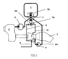
- the figure 1 is a schematic view of the control system of a pneumatic valve closing the oil tank outlet in an aircraft engine, according to the present invention.
- the system proposed according to the invention and represented on the figure 1 uses the pneumatic energy, for example that generated by the compressor 3 or that supplying the starter 8, to open an isolation valve 7 of the oil tank 1, closed at rest, ensuring both the protection of the circuit of oil in case of fire and an anti-siphon function.
- the isolation valve 7 is advantageously a valve valve connected to a jack bellows, which ensures its tightness while minimizing friction.
- the valve 7 is actuated either by the air pressure supplying the starter 9 or by that of the compressor 10, according to the position of a "shuttle" valve or incorporated 7A shuttle valve , which automatically selects the source of the highest pressure.
- This shuttle valve has two input gates connected in this case respectively to the air pressure supplying the starter and that of the compressor and an output port connected to the isolation valve 7. A ball shuttle between the two seats corresponding to the two entrance doors, the seat corresponding to the highest pressure being free.
- isolation valve 7 is open either when the engine is running or at the start. It is closed at rest or during a failure of the engine pressure in flight.
- the shuttle valve 7A can be advantageously adjusted without bias or with a bias to pass the starting transients of the engine.
- the isolation valve 7 closes as soon as there is no more air pressure, under the action of a return spring 7B.
- the oil tank is put in communication with the equipment of the lubrication circuit of the engine 2, via the pipe 4A and the pump 4 and, via the pipe 6A and the pump 6, with the reduction box ( power gear box ) 5, which has in this case exposed its own lubrication circuit.
Landscapes
- Engineering & Computer Science (AREA)
- Mechanical Engineering (AREA)
- General Engineering & Computer Science (AREA)
- Lubrication Of Internal Combustion Engines (AREA)
- Lubrication Details And Ventilation Of Internal Combustion Engines (AREA)
- General Details Of Gearings (AREA)
Claims (7)
- Turbinentriebwerk, bestehend aus einem Luftkompressor (3) sowie einem Schmierkreislauf, der wiederum einen Öl-Vorratsbehälter (1) umfasst; der besagte Ölvorratsbehälter (1) kann vom Rest des Schmierkreislaufs (4, 4A; 6, 6A) mithilfe eines Absperrventils (7) getrennt werden, das eine pneumatische Steuerung umfasst, um das Ventil in geöffneter und geschlossener Position zu halten, wenn das Turbinentriebwerk sich jeweils in Betrieb befindet bzw. im Stand gehalten wird, sowie um jeweils das Ventil beim Anhalten und wieder Anlaufen des Turbinentriebwerks zu öffnen bzw. zu schließen, wobei das besagte Absperrventil (7) dadurch gekennzeichnet ist, dass es mit einer Vorrichtung (7A) ausgestattet ist, die es ermöglicht, automatisch als Steuerung zwischen zwei Luftdruckquellen (9, 10) diejenige zu wählen, die über den höchsten Druck verfügt.
- Turbinentriebwerk gemäß Anspruch 1,
dadurch gekennzeichnet, dass es sich bei der ersten Druckquelle (10) um den aus dem Kompressor (3) austretenden Luftdruck handelt. - Turbinentriebwerk gemäß Anspruch 1,
dadurch gekennzeichnet, dass es sich bei der zweiten Druckquelle (9) um die pneumatische Steuerung handelt, die einem Signal zum Anlaufen des Turbinentriebwerks(8) entspricht, hierbei handelt es sich insbesondere um den Steuerluftdruck eines Luftdruckanlassers. - Turbinentriebwerk gemäß einem der vorherigen Ansprüche, dadurch gekennzeichnet, dass das Absperrventil (7) über die eine oder andere Druckluftquelle (9, 10), über ein Ventil-Schütz (7A), gesteuert wird, dessen Eingangstüren jeweils mit denen der Druckluftquellen (9, 10) und dessen Ausgangstür mit dem Absperrventil (7) verbunden sind.
- Turbinentriebwerk gemäß einem der vorherigen Ansprüche, dadurch gekennzeichnet, dass es sich bei dem Absperrventil (7) um ein mit einer Spindel mit Blasebalg ausgestattetes Rückstauventil handelt.
- Turbinentriebwerk gemäß einem der vorherigen Ansprüche, dadurch gekennzeichnet, dass es sich bei dem Turbinentriebwerk um ein Propeller-Turbinen-Luftstrahltriebwerk handelt.
- Turbinentriebwerk gemäß Anspruch 6,
dadurch gekennzeichnet, dass das Absperrventil (7) es ermöglicht, den Öl-Vorratsbehälter (1) einerseits vom Rest des Schmierkreislaufes (4, 4A) des Propeller-Turbinen-Luftstrahltriebwerks und andererseits den Rest des Schmierkreislaufs (6, 6A) vom Getriebe (5) des Propeller-Turbinen-Luftstrahltriebwerks zu trennen.
Priority Applications (5)
| Application Number | Priority Date | Filing Date | Title |
|---|---|---|---|
| DE602006013168T DE602006013168D1 (de) | 2006-12-21 | 2006-12-21 | Absperrventil für den Ölkreislauf in einem Flugzeugmotor |
| ES06447130T ES2342317T3 (es) | 2006-12-21 | 2006-12-21 | Valvula de aislamiento del circuito de aceite en un motor de avion. |
| AT06447130T ATE462063T1 (de) | 2006-12-21 | 2006-12-21 | Absperrventil für den ölkreislauf in einem flugzeugmotor |
| EP06447130A EP1936122B1 (de) | 2006-12-21 | 2006-12-21 | Absperrventil für den Ölkreislauf in einem Flugzeugmotor |
| US11/958,021 US8020664B2 (en) | 2006-12-21 | 2007-12-17 | Isolation valve for the oil circuit of an airplane engine |
Applications Claiming Priority (1)
| Application Number | Priority Date | Filing Date | Title |
|---|---|---|---|
| EP06447130A EP1936122B1 (de) | 2006-12-21 | 2006-12-21 | Absperrventil für den Ölkreislauf in einem Flugzeugmotor |
Publications (2)
| Publication Number | Publication Date |
|---|---|
| EP1936122A1 EP1936122A1 (de) | 2008-06-25 |
| EP1936122B1 true EP1936122B1 (de) | 2010-03-24 |
Family
ID=37909850
Family Applications (1)
| Application Number | Title | Priority Date | Filing Date |
|---|---|---|---|
| EP06447130A Active EP1936122B1 (de) | 2006-12-21 | 2006-12-21 | Absperrventil für den Ölkreislauf in einem Flugzeugmotor |
Country Status (5)
| Country | Link |
|---|---|
| US (1) | US8020664B2 (de) |
| EP (1) | EP1936122B1 (de) |
| AT (1) | ATE462063T1 (de) |
| DE (1) | DE602006013168D1 (de) |
| ES (1) | ES2342317T3 (de) |
Cited By (1)
| Publication number | Priority date | Publication date | Assignee | Title |
|---|---|---|---|---|
| US8602165B2 (en) | 2008-09-18 | 2013-12-10 | United Technologies Corporation | Continuous supply fluid reservoir |
Families Citing this family (9)
| Publication number | Priority date | Publication date | Assignee | Title |
|---|---|---|---|---|
| US8356694B2 (en) * | 2007-08-28 | 2013-01-22 | Pratt & Whitney | Recirculating lubrication system with sealed lubrication oil storage |
| EP2202387B1 (de) * | 2008-12-23 | 2012-08-22 | Techspace Aero S.A. | Absperrventil für steuerlosen Ölkreislauf in einem Flugzeugmotor |
| DE102011012863A1 (de) * | 2011-03-03 | 2012-09-06 | Rolls-Royce Deutschland Ltd & Co Kg | Ölversorgungssystem für ein Flugtriebwerk |
| EP2801707B1 (de) * | 2013-05-10 | 2017-07-05 | Safran Aero Boosters SA | Schmierkreislauf eines Turbotriebwerks mit Überlaufventil für Windmilling |
| EP3044438B1 (de) | 2013-09-13 | 2018-07-04 | United Technologies Corporation | Überwachungssystem für schmierölhilfspumpe eines lüfterantriebssystems |
| FR3019583B1 (fr) * | 2014-04-08 | 2019-09-13 | Safran Aircraft Engines | Isolation d'un reservoir de fluide combustible relativement a une partie aval de systeme d'alimentation pour turbomachine en cas d'incendie |
| DE102015212030A1 (de) * | 2015-06-29 | 2016-12-29 | Skf Lubrication Systems Germany Gmbh | Vorrichtung zur automatischen Bereitstellung von Schmiermittel |
| FR3039591B1 (fr) | 2015-07-31 | 2017-08-25 | Snecma | Isolation d'un reservoir de turbomachine d'aeronef en cas d'incendie par fermeture d'une vanne sensible a la liberation d'un agent extincteur |
| FR3059718B1 (fr) * | 2016-12-02 | 2019-06-21 | Safran Aircraft Engines | Dispositif hydromecanique de coupure a hysteresis pour systeme de lubrification de turbomachine |
Family Cites Families (8)
| Publication number | Priority date | Publication date | Assignee | Title |
|---|---|---|---|---|
| US2688229A (en) * | 1948-07-30 | 1954-09-07 | Niles Bement Pond Co | Fuel and speed control for internalcombustion engines |
| US2666490A (en) * | 1950-05-03 | 1954-01-19 | United Aircraft Corp | Auxiliary drive for propeller pitch control |
| US4170873A (en) * | 1977-07-20 | 1979-10-16 | Avco Corporation | Lubrication system |
| US4452037A (en) * | 1982-04-16 | 1984-06-05 | Avco Corporation | Air purge system for gas turbine engine |
| US4531694A (en) * | 1982-10-18 | 1985-07-30 | Soloy Conversions, Ltd. | Turbine engine drive and mounting assembly for fixed wing aircraft |
| DE3714990A1 (de) * | 1987-05-06 | 1988-12-01 | Mtu Muenchen Gmbh | Propfan-turbotriebwerk |
| US7387189B2 (en) | 2003-08-14 | 2008-06-17 | United Technologies Corp. | Emergency lubrication system |
| GB0422241D0 (en) * | 2004-10-07 | 2004-11-10 | Rolls Royce Plc | Aeroengine oil tank fire protection system |
-
2006
- 2006-12-21 EP EP06447130A patent/EP1936122B1/de active Active
- 2006-12-21 ES ES06447130T patent/ES2342317T3/es active Active
- 2006-12-21 AT AT06447130T patent/ATE462063T1/de not_active IP Right Cessation
- 2006-12-21 DE DE602006013168T patent/DE602006013168D1/de active Active
-
2007
- 2007-12-17 US US11/958,021 patent/US8020664B2/en active Active
Cited By (2)
| Publication number | Priority date | Publication date | Assignee | Title |
|---|---|---|---|---|
| US8602165B2 (en) | 2008-09-18 | 2013-12-10 | United Technologies Corporation | Continuous supply fluid reservoir |
| US8997935B2 (en) | 2008-09-18 | 2015-04-07 | United Technologies Corporation | Continuous supply fluid reservoir |
Also Published As
| Publication number | Publication date |
|---|---|
| US20080264726A1 (en) | 2008-10-30 |
| ATE462063T1 (de) | 2010-04-15 |
| US8020664B2 (en) | 2011-09-20 |
| ES2342317T3 (es) | 2010-07-05 |
| EP1936122A1 (de) | 2008-06-25 |
| DE602006013168D1 (de) | 2010-05-06 |
Similar Documents
| Publication | Publication Date | Title |
|---|---|---|
| US8020664B2 (en) | Isolation valve for the oil circuit of an airplane engine | |
| EP2801707B1 (de) | Schmierkreislauf eines Turbotriebwerks mit Überlaufventil für Windmilling | |
| CA2894226C (fr) | Dispositif et procede d'augmentation temporaire de puissance | |
| US8291715B2 (en) | Bi-modal turbine assembly and starter / drive turbine system employing the same | |
| US10626802B2 (en) | Ducted gas turbine engine stability bleed valve with passive and active shutoff | |
| WO2015114266A1 (fr) | Alimentation en air d'un circuit de conditionnement d'air d'une cabine d'un aéronef a partir de son turbopropulseur | |
| FR2970303A1 (fr) | Circuit de carburant de turbomachine aeronautique a vanne de regulation de pression de carburant | |
| FR2742805A1 (fr) | Systeme d'aide au redemarrage des moteurs apres perte totale de motorisation | |
| FR3019221A1 (fr) | Dispositif hydraulique de demarrage d'urgence d'un turbomoteur, architecture d'un systeme propulsif d'un helicoptere multi-moteur equipe d'un tel dispositif et helicoptere correspondant | |
| FR2955896A1 (fr) | Procede et circuit de ventilation d'equipements d'un turboreacteur | |
| FR2972233A1 (fr) | Procede de suppression du decollement tournant dans une turbomachine | |
| US10808628B2 (en) | Hydromechanical cutoff device with hysteresis for a turbomachine lubrification system | |
| US10865715B2 (en) | Passive stability bleed valve with adjustable reference pressure regulator and remote override capability | |
| CA2799673C (fr) | Dispositif et procede de regulation d`un turbomoteur, et aeronef | |
| EP3942169B1 (de) | Leistungsabnahme von einem nd-körper und system zum entfernen von rückständen | |
| CA2962202C (fr) | Dispositif et procede de test d'integrite d'un systeme de reactivation rapide d'un turbomoteur d'un helicoptere | |
| EP3601765B1 (de) | Verbesserte vorrichtung zur temporären erhöhung der turbomaschinenleistung | |
| US20120036866A1 (en) | Auxiliary power unit with multiple fuel sources | |
| FR3099806A1 (fr) | Régulation anti-pompage d’un compresseur de charge équipant un groupe auxiliaire de puissance | |
| US10267326B2 (en) | Variable vane scheduling | |
| EP4296491B1 (de) | Öltank für eine turbomaschine mit unterem fach mit einem negativ-g-kompatiblen ölauslasskanal | |
| FR3143001A1 (fr) | Module de turbomachine equipe d’un accumulateur hydraulique et turbomachine le comportant | |
| FR2956380A1 (fr) | Procede et dispositif de protection contre des anomalies de commande de poussee de moteur d'avion | |
| FR3127526A1 (fr) | Turbomachine comprenant un systeme d’alimentation en huile | |
| FR3109966A1 (fr) | Procédé de commande et unité de commande pour éviter le pompage d’un compresseur de charge dans un groupe auxiliaire de puissance |
Legal Events
| Date | Code | Title | Description |
|---|---|---|---|
| PUAI | Public reference made under article 153(3) epc to a published international application that has entered the european phase |
Free format text: ORIGINAL CODE: 0009012 |
|
| AK | Designated contracting states |
Kind code of ref document: A1 Designated state(s): AT BE BG CH CY CZ DE DK EE ES FI FR GB GR HU IE IS IT LI LT LU LV MC NL PL PT RO SE SI SK TR |
|
| AX | Request for extension of the european patent |
Extension state: AL BA HR MK RS |
|
| 17P | Request for examination filed |
Effective date: 20081127 |
|
| 17Q | First examination report despatched |
Effective date: 20090114 |
|
| AKX | Designation fees paid |
Designated state(s): AT BE BG CH CY CZ DE DK EE ES FI FR GB GR HU IE IS IT LI LT LU LV MC NL PL PT RO SE SI SK TR |
|
| GRAP | Despatch of communication of intention to grant a patent |
Free format text: ORIGINAL CODE: EPIDOSNIGR1 |
|
| RAP1 | Party data changed (applicant data changed or rights of an application transferred) |
Owner name: TECHSPACE AERO S.A. |
|
| GRAS | Grant fee paid |
Free format text: ORIGINAL CODE: EPIDOSNIGR3 |
|
| GRAA | (expected) grant |
Free format text: ORIGINAL CODE: 0009210 |
|
| AK | Designated contracting states |
Kind code of ref document: B1 Designated state(s): AT BE BG CH CY CZ DE DK EE ES FI FR GB GR HU IE IS IT LI LT LU LV MC NL PL PT RO SE SI SK TR |
|
| REG | Reference to a national code |
Ref country code: GB Ref legal event code: FG4D Free format text: NOT ENGLISH |
|
| REG | Reference to a national code |
Ref country code: CH Ref legal event code: EP |
|
| REG | Reference to a national code |
Ref country code: IE Ref legal event code: FG4D |
|
| REF | Corresponds to: |
Ref document number: 602006013168 Country of ref document: DE Date of ref document: 20100506 Kind code of ref document: P |
|
| REG | Reference to a national code |
Ref country code: ES Ref legal event code: FG2A Ref document number: 2342317 Country of ref document: ES Kind code of ref document: T3 |
|
| REG | Reference to a national code |
Ref country code: NL Ref legal event code: VDEP Effective date: 20100324 |
|
| PG25 | Lapsed in a contracting state [announced via postgrant information from national office to epo] |
Ref country code: LT Free format text: LAPSE BECAUSE OF FAILURE TO SUBMIT A TRANSLATION OF THE DESCRIPTION OR TO PAY THE FEE WITHIN THE PRESCRIBED TIME-LIMIT Effective date: 20100324 |
|
| LTIE | Lt: invalidation of european patent or patent extension |
Effective date: 20100324 |
|
| PG25 | Lapsed in a contracting state [announced via postgrant information from national office to epo] |
Ref country code: AT Free format text: LAPSE BECAUSE OF FAILURE TO SUBMIT A TRANSLATION OF THE DESCRIPTION OR TO PAY THE FEE WITHIN THE PRESCRIBED TIME-LIMIT Effective date: 20100324 Ref country code: FI Free format text: LAPSE BECAUSE OF FAILURE TO SUBMIT A TRANSLATION OF THE DESCRIPTION OR TO PAY THE FEE WITHIN THE PRESCRIBED TIME-LIMIT Effective date: 20100324 Ref country code: LV Free format text: LAPSE BECAUSE OF FAILURE TO SUBMIT A TRANSLATION OF THE DESCRIPTION OR TO PAY THE FEE WITHIN THE PRESCRIBED TIME-LIMIT Effective date: 20100324 Ref country code: PL Free format text: LAPSE BECAUSE OF FAILURE TO SUBMIT A TRANSLATION OF THE DESCRIPTION OR TO PAY THE FEE WITHIN THE PRESCRIBED TIME-LIMIT Effective date: 20100324 Ref country code: SI Free format text: LAPSE BECAUSE OF FAILURE TO SUBMIT A TRANSLATION OF THE DESCRIPTION OR TO PAY THE FEE WITHIN THE PRESCRIBED TIME-LIMIT Effective date: 20100324 |
|
| REG | Reference to a national code |
Ref country code: IE Ref legal event code: FD4D |
|
| PG25 | Lapsed in a contracting state [announced via postgrant information from national office to epo] |
Ref country code: EE Free format text: LAPSE BECAUSE OF FAILURE TO SUBMIT A TRANSLATION OF THE DESCRIPTION OR TO PAY THE FEE WITHIN THE PRESCRIBED TIME-LIMIT Effective date: 20100324 Ref country code: GR Free format text: LAPSE BECAUSE OF FAILURE TO SUBMIT A TRANSLATION OF THE DESCRIPTION OR TO PAY THE FEE WITHIN THE PRESCRIBED TIME-LIMIT Effective date: 20100625 Ref country code: RO Free format text: LAPSE BECAUSE OF FAILURE TO SUBMIT A TRANSLATION OF THE DESCRIPTION OR TO PAY THE FEE WITHIN THE PRESCRIBED TIME-LIMIT Effective date: 20100324 Ref country code: SE Free format text: LAPSE BECAUSE OF FAILURE TO SUBMIT A TRANSLATION OF THE DESCRIPTION OR TO PAY THE FEE WITHIN THE PRESCRIBED TIME-LIMIT Effective date: 20100324 Ref country code: NL Free format text: LAPSE BECAUSE OF FAILURE TO SUBMIT A TRANSLATION OF THE DESCRIPTION OR TO PAY THE FEE WITHIN THE PRESCRIBED TIME-LIMIT Effective date: 20100324 |
|
| PG25 | Lapsed in a contracting state [announced via postgrant information from national office to epo] |
Ref country code: BG Free format text: LAPSE BECAUSE OF FAILURE TO SUBMIT A TRANSLATION OF THE DESCRIPTION OR TO PAY THE FEE WITHIN THE PRESCRIBED TIME-LIMIT Effective date: 20100624 Ref country code: SK Free format text: LAPSE BECAUSE OF FAILURE TO SUBMIT A TRANSLATION OF THE DESCRIPTION OR TO PAY THE FEE WITHIN THE PRESCRIBED TIME-LIMIT Effective date: 20100324 Ref country code: IS Free format text: LAPSE BECAUSE OF FAILURE TO SUBMIT A TRANSLATION OF THE DESCRIPTION OR TO PAY THE FEE WITHIN THE PRESCRIBED TIME-LIMIT Effective date: 20100724 Ref country code: CZ Free format text: LAPSE BECAUSE OF FAILURE TO SUBMIT A TRANSLATION OF THE DESCRIPTION OR TO PAY THE FEE WITHIN THE PRESCRIBED TIME-LIMIT Effective date: 20100324 |
|
| PLBE | No opposition filed within time limit |
Free format text: ORIGINAL CODE: 0009261 |
|
| STAA | Information on the status of an ep patent application or granted ep patent |
Free format text: STATUS: NO OPPOSITION FILED WITHIN TIME LIMIT |
|
| PG25 | Lapsed in a contracting state [announced via postgrant information from national office to epo] |
Ref country code: IE Free format text: LAPSE BECAUSE OF FAILURE TO SUBMIT A TRANSLATION OF THE DESCRIPTION OR TO PAY THE FEE WITHIN THE PRESCRIBED TIME-LIMIT Effective date: 20100324 Ref country code: PT Free format text: LAPSE BECAUSE OF FAILURE TO SUBMIT A TRANSLATION OF THE DESCRIPTION OR TO PAY THE FEE WITHIN THE PRESCRIBED TIME-LIMIT Effective date: 20100726 Ref country code: DK Free format text: LAPSE BECAUSE OF FAILURE TO SUBMIT A TRANSLATION OF THE DESCRIPTION OR TO PAY THE FEE WITHIN THE PRESCRIBED TIME-LIMIT Effective date: 20100324 |
|
| 26N | No opposition filed |
Effective date: 20101228 |
|
| PG25 | Lapsed in a contracting state [announced via postgrant information from national office to epo] |
Ref country code: MC Free format text: LAPSE BECAUSE OF NON-PAYMENT OF DUE FEES Effective date: 20101231 |
|
| REG | Reference to a national code |
Ref country code: CH Ref legal event code: PL |
|
| PG25 | Lapsed in a contracting state [announced via postgrant information from national office to epo] |
Ref country code: CH Free format text: LAPSE BECAUSE OF NON-PAYMENT OF DUE FEES Effective date: 20101231 Ref country code: LI Free format text: LAPSE BECAUSE OF NON-PAYMENT OF DUE FEES Effective date: 20101231 |
|
| REG | Reference to a national code |
Ref country code: ES Ref legal event code: FD2A Effective date: 20120206 |
|
| PG25 | Lapsed in a contracting state [announced via postgrant information from national office to epo] |
Ref country code: ES Free format text: LAPSE BECAUSE OF NON-PAYMENT OF DUE FEES Effective date: 20101222 |
|
| PG25 | Lapsed in a contracting state [announced via postgrant information from national office to epo] |
Ref country code: CY Free format text: LAPSE BECAUSE OF FAILURE TO SUBMIT A TRANSLATION OF THE DESCRIPTION OR TO PAY THE FEE WITHIN THE PRESCRIBED TIME-LIMIT Effective date: 20100324 |
|
| PG25 | Lapsed in a contracting state [announced via postgrant information from national office to epo] |
Ref country code: LU Free format text: LAPSE BECAUSE OF NON-PAYMENT OF DUE FEES Effective date: 20101221 Ref country code: HU Free format text: LAPSE BECAUSE OF FAILURE TO SUBMIT A TRANSLATION OF THE DESCRIPTION OR TO PAY THE FEE WITHIN THE PRESCRIBED TIME-LIMIT Effective date: 20100925 |
|
| PG25 | Lapsed in a contracting state [announced via postgrant information from national office to epo] |
Ref country code: TR Free format text: LAPSE BECAUSE OF FAILURE TO SUBMIT A TRANSLATION OF THE DESCRIPTION OR TO PAY THE FEE WITHIN THE PRESCRIBED TIME-LIMIT Effective date: 20100324 |
|
| REG | Reference to a national code |
Ref country code: FR Ref legal event code: PLFP Year of fee payment: 10 |
|
| REG | Reference to a national code |
Ref country code: FR Ref legal event code: PLFP Year of fee payment: 11 |
|
| PGFP | Annual fee paid to national office [announced via postgrant information from national office to epo] |
Ref country code: IT Payment date: 20161125 Year of fee payment: 11 |
|
| REG | Reference to a national code |
Ref country code: FR Ref legal event code: PLFP Year of fee payment: 12 |
|
| PGFP | Annual fee paid to national office [announced via postgrant information from national office to epo] |
Ref country code: DE Payment date: 20171120 Year of fee payment: 12 |
|
| PGFP | Annual fee paid to national office [announced via postgrant information from national office to epo] |
Ref country code: GB Payment date: 20171121 Year of fee payment: 12 |
|
| PG25 | Lapsed in a contracting state [announced via postgrant information from national office to epo] |
Ref country code: IT Free format text: LAPSE BECAUSE OF NON-PAYMENT OF DUE FEES Effective date: 20171221 |
|
| REG | Reference to a national code |
Ref country code: DE Ref legal event code: R119 Ref document number: 602006013168 Country of ref document: DE |
|
| GBPC | Gb: european patent ceased through non-payment of renewal fee |
Effective date: 20181221 |
|
| PG25 | Lapsed in a contracting state [announced via postgrant information from national office to epo] |
Ref country code: DE Free format text: LAPSE BECAUSE OF NON-PAYMENT OF DUE FEES Effective date: 20190702 |
|
| PG25 | Lapsed in a contracting state [announced via postgrant information from national office to epo] |
Ref country code: GB Free format text: LAPSE BECAUSE OF NON-PAYMENT OF DUE FEES Effective date: 20181221 |
|
| PGFP | Annual fee paid to national office [announced via postgrant information from national office to epo] |
Ref country code: FR Payment date: 20251222 Year of fee payment: 20 |
|
| PGFP | Annual fee paid to national office [announced via postgrant information from national office to epo] |
Ref country code: BE Payment date: 20251224 Year of fee payment: 20 |