EP1936141A2 - Soupape de réglage d'un milieu s'écoulant - Google Patents
Soupape de réglage d'un milieu s'écoulant Download PDFInfo
- Publication number
- EP1936141A2 EP1936141A2 EP07019591A EP07019591A EP1936141A2 EP 1936141 A2 EP1936141 A2 EP 1936141A2 EP 07019591 A EP07019591 A EP 07019591A EP 07019591 A EP07019591 A EP 07019591A EP 1936141 A2 EP1936141 A2 EP 1936141A2
- Authority
- EP
- European Patent Office
- Prior art keywords
- valve
- housing
- housing part
- web
- welding
- Prior art date
- Legal status (The legal status is an assumption and is not a legal conclusion. Google has not performed a legal analysis and makes no representation as to the accuracy of the status listed.)
- Withdrawn
Links
Images

Classifications
-
- F—MECHANICAL ENGINEERING; LIGHTING; HEATING; WEAPONS; BLASTING
- F01—MACHINES OR ENGINES IN GENERAL; ENGINE PLANTS IN GENERAL; STEAM ENGINES
- F01P—COOLING OF MACHINES OR ENGINES IN GENERAL; COOLING OF INTERNAL-COMBUSTION ENGINES
- F01P7/00—Controlling of coolant flow
- F01P7/14—Controlling of coolant flow the coolant being liquid
- F01P7/16—Controlling of coolant flow the coolant being liquid by thermostatic control
-
- B—PERFORMING OPERATIONS; TRANSPORTING
- B29—WORKING OF PLASTICS; WORKING OF SUBSTANCES IN A PLASTIC STATE IN GENERAL
- B29C—SHAPING OR JOINING OF PLASTICS; SHAPING OF MATERIAL IN A PLASTIC STATE, NOT OTHERWISE PROVIDED FOR; AFTER-TREATMENT OF THE SHAPED PRODUCTS, e.g. REPAIRING
- B29C65/00—Joining or sealing of preformed parts, e.g. welding of plastics materials; Apparatus therefor
- B29C65/48—Joining or sealing of preformed parts, e.g. welding of plastics materials; Apparatus therefor using adhesives, i.e. using supplementary joining material; solvent bonding
-
- B—PERFORMING OPERATIONS; TRANSPORTING
- B29—WORKING OF PLASTICS; WORKING OF SUBSTANCES IN A PLASTIC STATE IN GENERAL
- B29C—SHAPING OR JOINING OF PLASTICS; SHAPING OF MATERIAL IN A PLASTIC STATE, NOT OTHERWISE PROVIDED FOR; AFTER-TREATMENT OF THE SHAPED PRODUCTS, e.g. REPAIRING
- B29C66/00—General aspects of processes or apparatus for joining preformed parts
- B29C66/01—General aspects dealing with the joint area or with the area to be joined
- B29C66/05—Particular design of joint configurations
- B29C66/10—Particular design of joint configurations particular design of the joint cross-sections
- B29C66/13—Single flanged joints; Fin-type joints; Single hem joints; Edge joints; Interpenetrating fingered joints; Other specific particular designs of joint cross-sections not provided for in groups B29C66/11 - B29C66/12
- B29C66/131—Single flanged joints, i.e. one of the parts to be joined being rigid and flanged in the joint area
- B29C66/1312—Single flange to flange joints, the parts to be joined being rigid
-
- B—PERFORMING OPERATIONS; TRANSPORTING
- B29—WORKING OF PLASTICS; WORKING OF SUBSTANCES IN A PLASTIC STATE IN GENERAL
- B29C—SHAPING OR JOINING OF PLASTICS; SHAPING OF MATERIAL IN A PLASTIC STATE, NOT OTHERWISE PROVIDED FOR; AFTER-TREATMENT OF THE SHAPED PRODUCTS, e.g. REPAIRING
- B29C66/00—General aspects of processes or apparatus for joining preformed parts
- B29C66/01—General aspects dealing with the joint area or with the area to be joined
- B29C66/32—Measures for keeping the burr form under control; Avoiding burr formation; Shaping the burr
- B29C66/322—Providing cavities in the joined article to collect the burr
-
- G—PHYSICS
- G05—CONTROLLING; REGULATING
- G05D—SYSTEMS FOR CONTROLLING OR REGULATING NON-ELECTRIC VARIABLES
- G05D23/00—Control of temperature
- G05D23/01—Control of temperature without auxiliary power
- G05D23/02—Control of temperature without auxiliary power with sensing element expanding and contracting in response to changes of temperature
- G05D23/021—Control of temperature without auxiliary power with sensing element expanding and contracting in response to changes of temperature the sensing element being a non-metallic solid, e.g. elastomer, paste
- G05D23/022—Control of temperature without auxiliary power with sensing element expanding and contracting in response to changes of temperature the sensing element being a non-metallic solid, e.g. elastomer, paste the sensing element being placed within a regulating fluid flow
-
- B—PERFORMING OPERATIONS; TRANSPORTING
- B29—WORKING OF PLASTICS; WORKING OF SUBSTANCES IN A PLASTIC STATE IN GENERAL
- B29C—SHAPING OR JOINING OF PLASTICS; SHAPING OF MATERIAL IN A PLASTIC STATE, NOT OTHERWISE PROVIDED FOR; AFTER-TREATMENT OF THE SHAPED PRODUCTS, e.g. REPAIRING
- B29C65/00—Joining or sealing of preformed parts, e.g. welding of plastics materials; Apparatus therefor
- B29C65/02—Joining or sealing of preformed parts, e.g. welding of plastics materials; Apparatus therefor by heating, with or without pressure
- B29C65/06—Joining or sealing of preformed parts, e.g. welding of plastics materials; Apparatus therefor by heating, with or without pressure using friction, e.g. spin welding
-
- B—PERFORMING OPERATIONS; TRANSPORTING
- B29—WORKING OF PLASTICS; WORKING OF SUBSTANCES IN A PLASTIC STATE IN GENERAL
- B29C—SHAPING OR JOINING OF PLASTICS; SHAPING OF MATERIAL IN A PLASTIC STATE, NOT OTHERWISE PROVIDED FOR; AFTER-TREATMENT OF THE SHAPED PRODUCTS, e.g. REPAIRING
- B29C65/00—Joining or sealing of preformed parts, e.g. welding of plastics materials; Apparatus therefor
- B29C65/02—Joining or sealing of preformed parts, e.g. welding of plastics materials; Apparatus therefor by heating, with or without pressure
- B29C65/08—Joining or sealing of preformed parts, e.g. welding of plastics materials; Apparatus therefor by heating, with or without pressure using ultrasonic vibrations
-
- B—PERFORMING OPERATIONS; TRANSPORTING
- B29—WORKING OF PLASTICS; WORKING OF SUBSTANCES IN A PLASTIC STATE IN GENERAL
- B29C—SHAPING OR JOINING OF PLASTICS; SHAPING OF MATERIAL IN A PLASTIC STATE, NOT OTHERWISE PROVIDED FOR; AFTER-TREATMENT OF THE SHAPED PRODUCTS, e.g. REPAIRING
- B29C65/00—Joining or sealing of preformed parts, e.g. welding of plastics materials; Apparatus therefor
- B29C65/02—Joining or sealing of preformed parts, e.g. welding of plastics materials; Apparatus therefor by heating, with or without pressure
- B29C65/14—Joining or sealing of preformed parts, e.g. welding of plastics materials; Apparatus therefor by heating, with or without pressure using wave energy, i.e. electromagnetic radiation, or particle radiation
- B29C65/16—Laser beams
-
- B—PERFORMING OPERATIONS; TRANSPORTING
- B29—WORKING OF PLASTICS; WORKING OF SUBSTANCES IN A PLASTIC STATE IN GENERAL
- B29C—SHAPING OR JOINING OF PLASTICS; SHAPING OF MATERIAL IN A PLASTIC STATE, NOT OTHERWISE PROVIDED FOR; AFTER-TREATMENT OF THE SHAPED PRODUCTS, e.g. REPAIRING
- B29C66/00—General aspects of processes or apparatus for joining preformed parts
- B29C66/50—General aspects of joining tubular articles; General aspects of joining long products, i.e. bars or profiled elements; General aspects of joining single elements to tubular articles, hollow articles or bars; General aspects of joining several hollow-preforms to form hollow or tubular articles
- B29C66/51—Joining tubular articles, profiled elements or bars; Joining single elements to tubular articles, hollow articles or bars; Joining several hollow-preforms to form hollow or tubular articles
- B29C66/54—Joining several hollow-preforms, e.g. half-shells, to form hollow articles, e.g. for making balls, containers; Joining several hollow-preforms, e.g. half-cylinders, to form tubular articles
-
- B—PERFORMING OPERATIONS; TRANSPORTING
- B29—WORKING OF PLASTICS; WORKING OF SUBSTANCES IN A PLASTIC STATE IN GENERAL
- B29L—INDEXING SCHEME ASSOCIATED WITH SUBCLASS B29C, RELATING TO PARTICULAR ARTICLES
- B29L2031/00—Other particular articles
- B29L2031/748—Machines or parts thereof not otherwise provided for
- B29L2031/7506—Valves
Definitions
- the invention relates to a valve for controlling a flowing medium, in particular thermostatic valve for the cooling circuit of an internal combustion engine, with the other features in the preamble of claim 1.
- Valves of this type are known whose valve body is e.g. consists of two housing parts, which are fixedly connected to each other along a parting plane by screws or clips, wherein for sealing a sealing element is interposed therebetween. Individual components of this valve or valve housing are each integral therewith, e.g. Applicable to any inlet nozzle and outlet nozzle. Also the attachment of the valve to holders or the like. serving fasteners are integral with the valve body. Such a design is complex and not very adaptable.
- the invention has for its object to provide a valve of the type mentioned, which allows a modular design with all the resulting advantages in terms of the housing parts and / or individual valve components.
- valve of the type mentioned according to the invention by the features in claim 1.
- the at least two interconnected housing parts and / or individual, with a housing part and / or mutually firmly connectable valve components are fixed by gluing or preferably by welding, with respect to these elements of the valve, a modular design is possible and at the same time a simple, inexpensive and Reliable solid and pressure-tight connection.
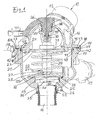
- a valve 10 is shown schematically, which generally serves to control a flowing medium.
- this valve 10 is designed as a thermostatic valve 11, which is used for the cooling circuit of an internal combustion engine.
- the valve or the like as other control valve, exhaust gas recirculation valve or the like. serve.
- the valve 10 has a valve housing 12, which has at least one inlet connection 13 and at least one outlet connection, in the embodiment shown, two outlet connection pieces 14, 15.
- the valve housing 12 is composed of at least two housing parts 16 and 17, which are tightly and firmly connected to each other.
- the housing parts 16 and 17 are here juxtaposed within a parting plane 18 which extends substantially perpendicular to the longitudinal central axis 19 of the valve housing 12.
- the valve housing 12 is composed of more than two housing parts, wherein the parting planes, within which the individual housing parts are juxtaposed, can be aligned differently than the parting plane 18.
- the valve 10, in particular thermostatic valve 11, further includes at least one valve element 20, which more or less releases or closes a valve opening 21 depending on the valve position.
- the valve opening 21 has an approximately frusto-conical valve seat 23, for example, on which the valve element 20, which is designed here as a valve plate, in the in FIG Fig. 1 shown closed position is seated and held by a spring 24 in the closed position.
- the valve element 20 forms a main valve together with the valve seat 23.
- the thermostatic valve 11 also has a short-circuit valve, which has a valve disk 25, by means of which a valve opening 26, which communicates with the discharge nozzle 14, is controllable.
- the valve element 20 is actuated by an actuator 27.
- the actuator 27 consists for example of a thermostatic working element 28, which inside a Housing 29 contains an expanding at an increase in temperature expansion.
- a housing 29 contains an expanding at an increase in temperature expansion.
- the expansion material immersed, for example, provided with an internal electric heater piston 30, which is supported and fixed to a housing part 16.
- the valve element 20 is seated, for example, in such a way that between the two axial relative movement in an axial direction is possible.
- the housing 29 has an annular stopper 31, on the expanding expansive material in the housing 29 and housing displacement in Fig. 1 down the valve member 20 positively entrained and moved downwards in the open position against the action of the spring 24 which rests from below on the valve member 20 and is supported at its other end to the bottom of the other housing part 17.
- the lower valve disk 25 is displaceable relative to a housing shoulder 32 and is pressed by means of a spring 33 axially downwards against an end stop 34.
- the spring 33 is supported at its other end on a ring stop 35 of the housing 29.
- the inlet pipe 13 may, for example, communicate with the internal combustion engine, while the outlet pipe 15 may be connected to the branch leading to the radiator.
- the other outlet connection 14 may be in the form of a bypass connection with the return to the internal combustion engine.
- the at least two housing parts such as the housing parts 16 and 17, and / or individual, with one of the housing parts 16, 17 and / or mutually firmly connectable valve components, which are explained in more detail below, by gluing or instead also by welding.
- adhesive bonding a variety of adhesive materials and adhesive methods are suitable, all of which are within the scope of the invention.
- welding attachment comes with preference an ultrasonic welding, laser welding, friction welding od.
- the valve housing 12 and / or the individual valve components are made of plastic. Based on Fig. 1 and 2 the welding attachment is primarily explained below.
- the actuator 27, in particular in the form of the thermostatic working element 28, has a particular electrical heating element contained within a housing 36 and therefore in Fig. 1 not visible.
- This heating element is accommodated with its housing 36 in a housing receptacle 37 of the valve housing 12, namely at least substantially accurate fit.
- the housing receptacle 37 is designed, for example, as a cylindrical opening 38, which merges via a stepped shoulder into a larger diameter section.
- the housing 36 is provided with a plug-like projection 39 adapted to the opening 38, which fits into the opening 38.
- the heating element is fastened with its housing 36 by welding or instead by gluing.
- the adhesive area or the welding area is located where the projection 39 engages in the opening 38 substantially accurately.
- a sealing ring 40 such as O-ring, held for sealing the weld or splice and further for sealing the electrical connections of the heating element with housing 36 against the interior 22 and the guided therein flowing medium of the valve housing 12 serves.
- This attachment of the electric heating element with housing 36 described type in the valve housing 12 by gluing or welding has many advantages. This results in a space-saving design and thus a compact valve 10. Furthermore, the manufacturing costs can be reduced, for example, by the fact that the attachment process by welding or gluing during non-productive times, for example, the injection molding process happens. Also advantageous is a high degree of flexibility due to modular design for other variants, for example, different connector positions and plug versions of the present at the end of the housing 36 connector 41. Another cost savings is due to the possibility of multiple use of the components.
- valve 10 Another special feature of the valve 10 is that at least two housing parts, for example, the housing parts 16 and 17, which are juxtaposed within the parting plane 18, by welding or gluing together firmly and tightly are connected.
- a housing part eg the in Fig. 1 Upper housing part 16, has in the region of the parting plane 18 facing the other housing part 17, protruding from the housing part 16 web 43, in particular ring land on which abuts when assembling the housing parts 16,17 for a welding attachment the end face on a ring land 50 of the housing part 17, wherein connect the materials of the web 43 and annular web 50 together in the welded joint.
- the housing part 17 instead has an only indicated groove 42, in particular in the form of a circumferential annular groove, which is open to the other housing part 16, wherein the web 43 is received and glued positively in the groove 42.
- This is the main attachment point, which provides the proper strength of the connection of the housing parts 16 and 17, can withstand high tensile loads and is used to optimize strength and weld release in this area.
- lateral, in particular radial, distance from the web 43 is at least one in the same direction, that is in Fig. 1 also down, projecting, in particular circumferential, edge web provided, which is supported with its end face on a facing surface of the other housing part 17 and is seated.
- an outer edge web 44 and an inner edge web 45 are each provided at a distance from the web 43.
- the outer edge web 44 extends on the outside and the inner edge web 45 on the inside of the housing part 16, wherein both edge webs 44, 45 are directed to the facing end face 46 of the other housing part 17 out. It can be seen that the edge web 44 extending on the outside of the housing part 16 extends obliquely with its end face 47.
- the area of the end face 46 of the housing part 17 assigned to this end face 47 also runs obliquely.
- the oblique course is such that these two surfaces slop off obliquely in the illustrated embodiment outwards and downwards. Because of this oblique course of the surfaces in contact with each other, a spewing radially outward is avoided during manufacture by welding.
- any expelled material is instead forced inwardly and toward the junction between lands 43 and 50.
- the other, the inside of the housing part 16 extending edge web 45 is tapered approximately wedge-shaped in cross-section on its end face 46 facing the end face, which is illustrated by the tip 48.
- the facing end face 46 of the housing part 17 includes an adapted, approximately V-shaped recessed groove 49, in particular annular groove. This configuration results when, in the area of the surfaces in contact with each other, welding is effected analogously to that in the region of the web 43 and the annular web 50. In the region of the web 43 and the annular web 50 and in the two edge webs 44 and 45, a welding attachment takes place Sch patbefest Trent the described, respectively facing Aufsitzdon with which the web 43 and the edge webs 44 and 45 in the region of the annular web 50 and the end face 46 of the other housing part 17 sit.
- the weld fastening in the region of the inner edge web 45 results in that a welding projection in the drawing is prevented radially inward, which in view of the inside 22 guided flowing medium would be disadvantageous. Instead, a welding expulsion is forced radially outward in the direction of the web 43 during attachment.
- the attachment by means of the inner edge web 45 has the further advantage that thereby the location of the main connection, namely the web 43 and the annular web 50, protected and sealed in the interior against exposure of the flowing medium 22 in the interior, for example, as cooling water in the form of a Water-glycol mixture is aggressive. This can not reach the main office.
- this radially inner fixed connection by means of the edge web 45 causes additional support of the main fastening point 43,50 under the pressure in the interior 22.
- the main attachment in the region of the webs 43 and 50 is particularly protected by the inner attachment point by means of the edge web 45 with respect to the stress.
- the pressure prevailing in the interior 22 could cause a peel load on the attachment between the webs 43 and 50, on the inside, e.g. would be critical for a welded joint. Due to the support by means of the outer edge web 44, such a peel load is avoided with respect to the main attachment point 43, 50.
- the main attachment point is protected by the inner edge web 45 from the attack of the guided inside the medium 22, an increased strength and increased life is achieved for this attachment point 43,50.
- valve 10 Another particularity of the valve 10 is that at least one inlet nozzle, e.g. the inlet nozzle 13, and / or a drain neck, e.g. the drain pipe 14 and / or 15, is attached to one of the housing parts 16,17 by welding or gluing. This will be clarified below with reference to the drain neck 14, wherein the same fastening method can also be provided for the inlet nozzle 13 and / or outlet nozzle 15.
- the discharge nozzle 14 has a fastening end 51 with a pipe edge 52 and a laterally, in particular radially, projecting flange 53.
- the receiving housing part 17 has a pipe edge 52 receiving insertion opening 54 which is surrounded by a support surface 55 against which the flange 53 abuts.
- fastening by welding or gluing is provided in the region of the insertion opening 54 with the pipe edge 52 engaging therein and / or the support surface 55 with adjacent flange 53.
- fastening by welding or gluing is provided in the region of the insertion opening 54 with the pipe edge 52 engaging therein and / or the support surface 55 with adjacent flange 53.
- fastening by welding or gluing is provided in the region of the insertion opening 54 with the pipe edge 52 engaging therein and / or the support surface 55 with adjacent flange 53.
- high flexibility is achieved by modular design for different variants.
- there is a cost savings through the possibility of multiple use of the components. It is understood that instead of the drain pipe
- FIG. 2 illustrates that on a housing part, for example, the housing part 16, corresponding threaded holes 57 are inserted into corresponding blind holes 56 and secured therein by welding or gluing.
- a threaded bushes 57 are held in a component 58, which can be connected in this way with the housing part 16.
- valve 10 it is provided in the valve 10 that on one of the housing parts 16,17 a not further shown mounting module similar e.g. the component 58 is fixed by welding or gluing, this mounting module can be used to attach the valve 10 to a holder. Again, there is the advantage of cost savings through the possibility of multiple use of individual components.
Landscapes
- Engineering & Computer Science (AREA)
- Mechanical Engineering (AREA)
- Physics & Mathematics (AREA)
- Chemical & Material Sciences (AREA)
- Combustion & Propulsion (AREA)
- General Engineering & Computer Science (AREA)
- Fluid Mechanics (AREA)
- General Physics & Mathematics (AREA)
- Automation & Control Theory (AREA)
- Valve Housings (AREA)
- Temperature-Responsive Valves (AREA)
Applications Claiming Priority (1)
| Application Number | Priority Date | Filing Date | Title |
|---|---|---|---|
| DE102006061441A DE102006061441A1 (de) | 2006-12-23 | 2006-12-23 | Ventil zur Regelung eines strömenden Mediums |
Publications (2)
| Publication Number | Publication Date |
|---|---|
| EP1936141A2 true EP1936141A2 (fr) | 2008-06-25 |
| EP1936141A3 EP1936141A3 (fr) | 2011-11-30 |
Family
ID=39315117
Family Applications (1)
| Application Number | Title | Priority Date | Filing Date |
|---|---|---|---|
| EP07019591A Withdrawn EP1936141A3 (fr) | 2006-12-23 | 2007-10-06 | Soupape de réglage d'un milieu s'écoulant |
Country Status (2)
| Country | Link |
|---|---|
| EP (1) | EP1936141A3 (fr) |
| DE (1) | DE102006061441A1 (fr) |
Cited By (2)
| Publication number | Priority date | Publication date | Assignee | Title |
|---|---|---|---|---|
| WO2016046340A2 (fr) | 2014-09-25 | 2016-03-31 | Vernet | Dispositif thermostatique de régulation de la circulation d'un fluide, ainsi que vanne thermostatique comprenant un tel dispositif |
| EP4001718B1 (fr) * | 2019-07-18 | 2026-01-21 | Fujikoki Corporation | Soupape de commutation de trajet d'écoulement |
Families Citing this family (2)
| Publication number | Priority date | Publication date | Assignee | Title |
|---|---|---|---|---|
| DE102008051267A1 (de) * | 2008-10-10 | 2010-04-15 | Mahle International Gmbh | Thermostatventil |
| DE102013111048A1 (de) * | 2013-10-07 | 2015-04-09 | Gustav Wahler Gmbh U. Co. Kg | Thermostatventil und Verfahren zum Herstellen eines solchen |
Family Cites Families (8)
| Publication number | Priority date | Publication date | Assignee | Title |
|---|---|---|---|---|
| US4281686A (en) * | 1979-11-23 | 1981-08-04 | Gerlitz Gordon R | Three way butterfly valve |
| GB9411617D0 (en) * | 1994-06-09 | 1994-08-03 | Rover Group | A thermostat assembly |
| JPH08132529A (ja) * | 1994-11-04 | 1996-05-28 | Toyota Motor Corp | 樹脂製品、樹脂製品の製造方法及び樹脂部材 |
| DE19501140A1 (de) * | 1995-01-17 | 1996-07-18 | Behr Thomson Dehnstoffregler | Thermostatisches Arbeitselement mit einem elektrischen Heizelement und Verfahren zum Einbringen des elektrischen Heizelementes in ein Gehäuse |
| JP2001193863A (ja) * | 2000-01-07 | 2001-07-17 | Nok Corp | サーモスタットハウジング |
| JP2002283455A (ja) * | 2001-03-26 | 2002-10-03 | Kyosan Denki Co Ltd | 樹脂部品の接合構造 |
| FR2840953B1 (fr) * | 2002-06-12 | 2004-09-03 | Mark Iv Systemes Moteurs Sa | Boitier de sortie d'eau muni d'un thermostat et procede de fabrication |
| CN1673583A (zh) * | 2004-03-26 | 2005-09-28 | 罗荣森 | 塑料截止阀的制作方法 |
-
2006
- 2006-12-23 DE DE102006061441A patent/DE102006061441A1/de not_active Withdrawn
-
2007
- 2007-10-06 EP EP07019591A patent/EP1936141A3/fr not_active Withdrawn
Non-Patent Citations (1)
| Title |
|---|
| None |
Cited By (5)
| Publication number | Priority date | Publication date | Assignee | Title |
|---|---|---|---|---|
| WO2016046340A2 (fr) | 2014-09-25 | 2016-03-31 | Vernet | Dispositif thermostatique de régulation de la circulation d'un fluide, ainsi que vanne thermostatique comprenant un tel dispositif |
| FR3026458A1 (fr) * | 2014-09-25 | 2016-04-01 | Vernet | Dispositif thermostatique de regulation de la circulation d'un fluide, ainsi que vanne thermostatique comprenant un tel dispositif |
| WO2016046340A3 (fr) * | 2014-09-25 | 2016-05-19 | Vernet | Dispositif thermostatique de régulation de la circulation d'un fluide, ainsi que vanne thermostatique comprenant un tel dispositif |
| US10386870B2 (en) | 2014-09-25 | 2019-08-20 | Vernet | Thermostatic device for controlling the flow of a fluid, and thermostatic valve comprising such a device |
| EP4001718B1 (fr) * | 2019-07-18 | 2026-01-21 | Fujikoki Corporation | Soupape de commutation de trajet d'écoulement |
Also Published As
| Publication number | Publication date |
|---|---|
| DE102006061441A1 (de) | 2008-06-26 |
| EP1936141A3 (fr) | 2011-11-30 |
Similar Documents
| Publication | Publication Date | Title |
|---|---|---|
| EP2051892B1 (fr) | Dispositif d'alimentation en air comprimé pour un véhicule utilitaire et cartouche de dessiccateur | |
| EP2092186B1 (fr) | Soupape d'injection de carburant pour moteurs à combustion interne | |
| DE202018106323U1 (de) | Wasserventilführungsrohr mit integriertem Schweissring und Wasserventil mit diesem Rohr | |
| EP2205922A1 (fr) | Échangeur thermique, notamment refroidisseur à huile | |
| EP2527944B1 (fr) | Vanne de régulation de pression à commande électromagnétique | |
| EP1960653B1 (fr) | Piston en deux pieces pour moteur a combustion interne | |
| DE102013200533B4 (de) | Ventilpatrone | |
| DE102008056245A1 (de) | Thermostatventil | |
| EP2530365B2 (fr) | Garniture de soupape pour une armature sanitaire | |
| EP1634003B1 (fr) | Unite de raccordement rapide pourvue d'une soupape de non-retour integree | |
| DE102005018904B3 (de) | Thermostatventil für das Kühlsystem einer Verbrennungskraftmaschine | |
| EP2235355B1 (fr) | Injecteur de carburant | |
| EP1936141A2 (fr) | Soupape de réglage d'un milieu s'écoulant | |
| DE102017106474A1 (de) | Temperaturempfindliche Ventileinrichtung | |
| EP3353455B1 (fr) | Soupape antiretour | |
| DE102019108382B4 (de) | Gehäuseoberteil für Hochdruckfilter und Hochdruckfilter | |
| DE3801410A1 (de) | Kraftstoffaufbereitungsvorrichtung | |
| EP1355057B1 (fr) | Dispositif pour la recirculation des gaz d'échappement d'un moteur à combustion interne | |
| EP3359851B1 (fr) | Électrovanne de commande | |
| DE4412683C2 (de) | Verbundwasserzähler | |
| EP0681098A1 (fr) | Vanne thermostatique | |
| CH688743A5 (de) | Tauchanker-Magnetventil. | |
| EP1619568B2 (fr) | clapet thermostatique | |
| DE29915384U1 (de) | Kombination aus einer Haupteinheit und wenigstens einer Anbau-Funktionseinheit | |
| DE10259107B4 (de) | Ventil |
Legal Events
| Date | Code | Title | Description |
|---|---|---|---|
| PUAI | Public reference made under article 153(3) epc to a published international application that has entered the european phase |
Free format text: ORIGINAL CODE: 0009012 |
|
| AK | Designated contracting states |
Kind code of ref document: A2 Designated state(s): AT BE BG CH CY CZ DE DK EE ES FI FR GB GR HU IE IS IT LI LT LU LV MC MT NL PL PT RO SE SI SK TR |
|
| AX | Request for extension of the european patent |
Extension state: AL BA HR MK RS |
|
| PUAL | Search report despatched |
Free format text: ORIGINAL CODE: 0009013 |
|
| AK | Designated contracting states |
Kind code of ref document: A3 Designated state(s): AT BE BG CH CY CZ DE DK EE ES FI FR GB GR HU IE IS IT LI LT LU LV MC MT NL PL PT RO SE SI SK TR |
|
| AX | Request for extension of the european patent |
Extension state: AL BA HR MK RS |
|
| RIC1 | Information provided on ipc code assigned before grant |
Ipc: F01P 7/16 20060101AFI20111025BHEP |
|
| AKY | No designation fees paid | ||
| REG | Reference to a national code |
Ref country code: DE Ref legal event code: R108 |
|
| REG | Reference to a national code |
Ref country code: DE Ref legal event code: R108 Effective date: 20120808 |
|
| STAA | Information on the status of an ep patent application or granted ep patent |
Free format text: STATUS: THE APPLICATION IS DEEMED TO BE WITHDRAWN |
|
| 18D | Application deemed to be withdrawn |
Effective date: 20120531 |