EP1936220A2 - Dispositif de transmission de couple - Google Patents
Dispositif de transmission de couple Download PDFInfo
- Publication number
- EP1936220A2 EP1936220A2 EP07022377A EP07022377A EP1936220A2 EP 1936220 A2 EP1936220 A2 EP 1936220A2 EP 07022377 A EP07022377 A EP 07022377A EP 07022377 A EP07022377 A EP 07022377A EP 1936220 A2 EP1936220 A2 EP 1936220A2
- Authority
- EP
- European Patent Office
- Prior art keywords
- torque transmission
- transmission device
- disk carrier
- connecting part
- windows
- Prior art date
- Legal status (The legal status is an assumption and is not a legal conclusion. Google has not performed a legal analysis and makes no representation as to the accuracy of the status listed.)
- Granted
Links
- 230000005540 biological transmission Effects 0.000 title claims abstract description 143
- 238000007789 sealing Methods 0.000 claims abstract description 146
- 230000008878 coupling Effects 0.000 claims description 7
- 238000010168 coupling process Methods 0.000 claims description 7
- 238000005859 coupling reaction Methods 0.000 claims description 7
- 241000446313 Lamella Species 0.000 claims description 5
- 238000002485 combustion reaction Methods 0.000 claims description 5
- 239000002184 metal Substances 0.000 claims description 5
- 238000009434 installation Methods 0.000 claims description 4
- 230000035515 penetration Effects 0.000 claims description 4
- 238000004080 punching Methods 0.000 claims description 3
- 239000002826 coolant Substances 0.000 description 12
- 210000001331 nose Anatomy 0.000 description 12
- 238000001816 cooling Methods 0.000 description 7
- 210000003128 head Anatomy 0.000 description 6
- 238000004519 manufacturing process Methods 0.000 description 4
- 238000010276 construction Methods 0.000 description 3
- 230000009977 dual effect Effects 0.000 description 3
- 229910000831 Steel Inorganic materials 0.000 description 2
- 239000000463 material Substances 0.000 description 2
- 230000008092 positive effect Effects 0.000 description 2
- 239000010959 steel Substances 0.000 description 2
- 208000032750 Device leakage Diseases 0.000 description 1
- 239000000969 carrier Substances 0.000 description 1
- 230000007423 decrease Effects 0.000 description 1
- 238000006073 displacement reaction Methods 0.000 description 1
- 239000000446 fuel Substances 0.000 description 1
- 238000002347 injection Methods 0.000 description 1
- 239000007924 injection Substances 0.000 description 1
- 238000001746 injection moulding Methods 0.000 description 1
- 230000003993 interaction Effects 0.000 description 1
Images


Classifications
-
- F—MECHANICAL ENGINEERING; LIGHTING; HEATING; WEAPONS; BLASTING
- F16—ENGINEERING ELEMENTS AND UNITS; GENERAL MEASURES FOR PRODUCING AND MAINTAINING EFFECTIVE FUNCTIONING OF MACHINES OR INSTALLATIONS; THERMAL INSULATION IN GENERAL
- F16D—COUPLINGS FOR TRANSMITTING ROTATION; CLUTCHES; BRAKES
- F16D13/00—Friction clutches
- F16D13/22—Friction clutches with axially-movable clutching members
- F16D13/38—Friction clutches with axially-movable clutching members with flat clutching surfaces, e.g. discs
- F16D13/52—Clutches with multiple lamellae ; Clutches in which three or more axially moveable members are fixed alternately to the shafts to be coupled and are pressed from one side towards an axially-located member
-
- F—MECHANICAL ENGINEERING; LIGHTING; HEATING; WEAPONS; BLASTING
- F16—ENGINEERING ELEMENTS AND UNITS; GENERAL MEASURES FOR PRODUCING AND MAINTAINING EFFECTIVE FUNCTIONING OF MACHINES OR INSTALLATIONS; THERMAL INSULATION IN GENERAL
- F16D—COUPLINGS FOR TRANSMITTING ROTATION; CLUTCHES; BRAKES
- F16D13/00—Friction clutches
- F16D13/58—Details
- F16D13/72—Features relating to cooling
-
- F—MECHANICAL ENGINEERING; LIGHTING; HEATING; WEAPONS; BLASTING
- F16—ENGINEERING ELEMENTS AND UNITS; GENERAL MEASURES FOR PRODUCING AND MAINTAINING EFFECTIVE FUNCTIONING OF MACHINES OR INSTALLATIONS; THERMAL INSULATION IN GENERAL
- F16D—COUPLINGS FOR TRANSMITTING ROTATION; CLUTCHES; BRAKES
- F16D2300/00—Special features for couplings or clutches
- F16D2300/02—Overheat protection, i.e. means for protection against overheating
- F16D2300/021—Cooling features not provided for in group F16D13/72 or F16D25/123, e.g. heat transfer details
- F16D2300/0214—Oil or fluid cooling
-
- F—MECHANICAL ENGINEERING; LIGHTING; HEATING; WEAPONS; BLASTING
- F16—ENGINEERING ELEMENTS AND UNITS; GENERAL MEASURES FOR PRODUCING AND MAINTAINING EFFECTIVE FUNCTIONING OF MACHINES OR INSTALLATIONS; THERMAL INSULATION IN GENERAL
- F16D—COUPLINGS FOR TRANSMITTING ROTATION; CLUTCHES; BRAKES
- F16D2300/00—Special features for couplings or clutches
- F16D2300/08—Details or arrangements of sealings not provided for in group F16D3/84
Definitions
- the invention relates to a torque transmission device, in particular in the drive train of a motor vehicle for torque transmission between a drive unit, in particular an internal combustion engine, and a transmission, with at least one multi-plate clutch, in particular a double blade clutch comprising at least one disk set, the outer disk, which are rotatably connected to an outer disk carrier , and inner disks which are non-rotatably connected to an inner disk carrier, and at least one actuating lever means for actuating the multi-plate clutch, wherein a pressure transmission means between the disk set and the actuating lever means extends through at least one through hole which is recessed in a support means.
- a multi-plate clutch in particular a double blade clutch comprising at least one disk set, the outer disk, which are rotatably connected to an outer disk carrier , and inner disks which are non-rotatably connected to an inner disk carrier
- at least one actuating lever means for actuating the multi-plate clutch
- the object of the invention is to provide a torque transmission device according to the preamble of claim 1 or 24, which is simple in construction and inexpensive to produce.
- the cooling of the disk pack should be improved.
- the object is achieved in a torque transmission device according to the preamble of claim 1, characterized in that a sealing device is arranged between the inner disk carrier and the through hole.
- a sealing device is arranged between the inner disk carrier and the through hole.
- a preferred embodiment of the torque transmission device is characterized in that the sealing device comprises a sealing ring which overlaps an interface between the inner disk carrier and the disk set in the radial direction. Thereby, an undesired leakage of cooling medium in the axial direction through the through holes in the support device is prevented.
- a further preferred embodiment of the torque transmission device is characterized in that the sealing ring, at least partially, a substantially L-shaped, U-shaped or C-shaped cross-section.
- the C-shaped, U-shaped or L-shaped cross-section is opened to the disk pack.
- a further preferred embodiment of the torque transmission device is characterized in that the sealing ring, viewed in cross-section, has a leg which is arranged in the radial direction between the pressure ring and one or the outer disk carrier one or the second multi-plate clutch, which is arranged radially within the first multi-plate clutch , As a result, the sealing ring is positioned in the radial direction.
- a further preferred embodiment of the torque transmission device is characterized in that the sealing ring, viewed in cross-section, has a leg which is arranged offset in the axial direction and radially outside of the inner disk carrier. As a result, the cooling medium is passed between the outer disk carrier and the associated disk pack.
- Another preferred exemplary embodiment of the torque transmission device is characterized in that the end of the leg is arranged between the inner disk carrier and an associated disk.
- the lamella is preferably an end lamella.
- a further preferred embodiment of the torque transmission device is characterized in that the sealing ring, viewed in cross-section, has a further leg, which is arranged offset in the axial direction and radially inwardly of the inner disk carrier. As a result, leakage of cooling medium in the axial direction is reliably prevented.
- a further preferred embodiment of the torque transmission device is characterized in that the sealing device is designed as a transport safety device.
- the sealing device prevents lamellae of the lamella packet from coming off the associated lamella carrier.
- a further preferred embodiment of the torque transmission device is characterized in that the sealing device comprises a built-in fuse.
- the sealing device is designed, for example prestressed, that an undesired release of the sealing device after its installation is prevented.
- a further preferred embodiment of the torque transmission device is characterized in that the built-in safety device comprises a latching device, which causes a latching of the sealing device during its installation.
- the built-in safety device comprises a latching device, which causes a latching of the sealing device during its installation.
- a further preferred embodiment of the torque transmission device is characterized in that the built-in safety is designed as a bayonet lock.
- the sealing device is first inserted in the axial direction and then rotated in order to fix or position the sealing device and other parts in a secure manner.
- a further preferred exemplary embodiment of the torque transmission device is characterized in that the sealing device, in particular the sealing ring, has at least one lug, one hook and / or one limb which, at least partially, extends radially inwards and into a depression, a through-hole or engages a groove which is provided in one or the outer disk carrier one or the second multi-plate clutch, which is arranged radially within the first multi-plate clutch.
- the sealing device in particular the sealing ring, has at least one lug, one hook and / or one limb which, at least partially, extends radially inwards and into a depression, a through-hole or engages a groove which is provided in one or the outer disk carrier one or the second multi-plate clutch, which is arranged radially within the first multi-plate clutch.
- Another preferred embodiment of the torque transmission device is characterized in that the nose, the hook or leg is resiliently biased. This can prevent unwanted play that could cause rattling noises.
- Another preferred embodiment of the torque transmission device is characterized in that the sealing ring is resiliently biased. Due to the bias of the sealing ring can be centered.
- a further preferred embodiment of the torque transmission device is characterized in that the sealing device is designed so that the opening movement of the multi-plate clutch is supported by the sealing device. According to another Aspect of the invention is used for this purpose, the bias of the sealing device or parts of the sealing device.
- a further preferred embodiment of the torque transmission device is characterized in that the sealing device is designed so that the sealing device exerts its sealing function only when the multi-plate clutch is closed. When the multi-plate clutch is opened, a gap between the sealing device and another part may occur.
- a further preferred embodiment of the torque transmission device is characterized in that the sealing device is stamped and / or formed from sheet metal. As a result, the production costs can be reduced.
- a further preferred embodiment of the torque transmission device is characterized in that the sealing device is formed from plastic.
- the sealing device is designed as an injection molded part.
- a further preferred embodiment of the torque transmission device is characterized in that the sealing device has at least one snap hook, which engages in an opening of the support means.
- the sealing device has at least one snap hook, which engages in an opening of the support means.
- a fixation of the sealing device on the support device is made possible in a simple manner.
- a plurality of snap hooks are formed on the sealing device.
- a further preferred exemplary embodiment of the torque transmission device is characterized in that the pressure ring comprises centering means. As a result, the centering of the pressure ring during installation is simplified.
- a further preferred exemplary embodiment of the torque transmission device is characterized in that the pressure ring, in particular radially inward, has lugs with side surfaces which serve to center the pressure ring.
- the side surfaces preferably interact with a toothing.
- a further preferred embodiment of the torque transmission device is characterized in that the pressure ring, in particular radially outward, teeth with flanks has, which serve to center the pressure ring.
- the teeth with the flanks interact with another toothing.
- a further preferred embodiment of the torque transmission device is characterized in that the pressure ring, preferably radially outside, has a bent edge region.
- the bent edge area serves, for example, to increase the rigidity.
- the bent-over edge region can also serve for centering.
- the outer disk carrier of the inner multi-plate clutch is in two parts from a toothed body, which is rotatably connected via a toothing with the outer disk of the inner multi-plate clutch, and a connecting part is composed by the Outer plate carrier of the inner multi-plate clutch rotatably connected to the outer disc carrier of the outer multi-plate clutch.
- An embodiment of the torque transmission device is characterized in that the toothing body is formed from a sheet metal part by roll forming. As a result, the production of the toothing is considerably simplified.
- a further preferred embodiment of the torque transmission device is characterized in that the outer disk carrier of the outer multi-plate clutch is connected by a plug connection with the connecting part. Through the connector assembly is simplified.
- a further preferred embodiment of the torque transmission device is characterized in that the outer disk carrier of the outer multi-plate clutch has recesses into which engage webs, which are provided on the connecting part. This is created in a simple manner via a positive connection between the toothing body of the outer disk carrier and the connecting part.
- a further preferred embodiment of the torque transmission device is characterized in that the width of the webs is selected such that a punching of the webs from radially outside to inside or vice versa in the region of tooth tips of the toothing is possible.
- the width is the extension of the webs in the circumferential direction.
- a further preferred embodiment of the torque transmission device is characterized in that the toothed body is conically formed at its tip circle to the open ends. As a result, a tension between the two parts is made possible when pushing or attaching the connecting part to the toothing body. This can reduce or eliminate unwanted radial play.
- a further preferred embodiment of the torque transmission device is characterized in that the webs extend in the radial direction.
- a plurality of webs are spokes-like distributed over the circumference of the connecting part.
- a further preferred embodiment of the torque transmission device is characterized in that the webs extend in the circumferential direction in each case between two web windows, which are provided in the connecting part.
- the bridge windows are essentially rectangular.
- a further preferred embodiment of the torque transmission device is characterized in that the connecting part has finger windows, which allow the penetration of fingers, which emanate from a or the pressure ring.
- the disk set of the associated multi-plate clutch is coupled to the operating lever device.
- Another preferred embodiment of the torque transmission device is characterized in that the connecting part has half as many finger windows as teeth. This division has proven to be particularly advantageous in the context of the present invention.
- a further preferred embodiment of the torque transmission device is characterized in that the connecting part has the same number of finger windows as web window. Preferably, each finger window is associated with a web window.
- a further preferred exemplary embodiment of the torque transmission device is characterized in that the finger windows are arranged radially inside and in the circumferential direction overlapping the web windows. As a result, a uniform weight distribution is achieved.
- a further preferred embodiment of the torque transmission device is characterized in that the finger windows and / or the web window are arranged distributed uniformly in the circumferential direction. This simplifies assembly.
- a further preferred embodiment of the torque transmission device is characterized in that the connecting part surrounds the outer disk carrier of the outer multi-plate clutch and / or supports outer tooth heads of the outer disk carrier of the outer multi-plate clutch in the radial direction. This increases the speed stability.
- a further preferred embodiment of the torque transmission device is characterized in that the connecting part has an internal toothing, which is in engagement with an external toothing of the toothed body of the outer disk carrier of the inner multi-plate clutch.
- the rear side of the lamellar toothing is used for producing the rotationally fixed connection or plug connection.
- a further preferred embodiment of the torque transmission device is characterized in that the toothed body has issued grooves which constitute an axial stop for the connecting part.
- the grooves are areas that are punched out or pushed out between the teeth of the material of the toothing body.
- a further preferred embodiment of the torque transmission device is characterized in that the issued grooves, with respect to the center of the webs of the connecting part, are arranged symmetrically. As a result, the strength of the connector is increased.
- a further preferred embodiment of the torque transmission device is characterized in that every second tooth of the toothed body of the outer disk carrier the inner multi-plate clutch has a flared groove. This allows a high stability of the connector.
- a further preferred embodiment of the torque transmission device is characterized in that the outer disk carrier of the outer multi-plate clutch has a toothing with the same number of teeth as the toothing body of the outer disk carrier of the inner multi-plate clutch. This has proved to be particularly advantageous in the context of the present invention.
- the above-stated object is achieved in that the outer disk carrier of the outer multi-plate clutch comprises a toothed body, which is connected by a spline with the connecting part. This simplifies assembly.
- a preferred embodiment of the torque transmission device is characterized in that toothed windows are provided in the connecting part.
- the toothed windows are through-holes which extend in the axial direction through the connecting part.
- the toothed windows each have at least one radially inwardly extending external tooth.
- the external tooth is arranged centrally in the tooth window.
- a further preferred exemplary embodiment of the torque transmission device is characterized in that the toothed windows each have at least one inner tooth extending radially outwards.
- an external tooth is arranged between two internal teeth.
- a further preferred embodiment of the torque transmission device is characterized in that the arrangement of the inner teeth and / or the outer teeth is selected so that a punch has a sufficient cross-section. As a result, the production is simplified by punching.
- a further preferred exemplary embodiment of the torque transmission device is characterized in that the outer disk carrier of the outer multi-disk clutch is supported in the radial direction on the outer teeth, in particular on the flanks of the outer teeth, of the connecting part. This increases the speed stability.
- the rear side of the multi-plate toothing is used for producing the rotationally fixed connection or the plug connection.
- a further preferred embodiment of the torque transmission device is characterized in that the toothing body of the outer disk carrier of the outer multi-plate clutch has issued grooves which constitute an axial stop for the connecting part.
- the grooves are preferably areas that are pressed out between the teeth of the material of the toothing body.
- a further preferred embodiment of the torque transmission device is characterized in that the issued grooves, with respect to the center of the tooth window of the connecting part, are arranged symmetrically. As a result, the strength of the plug-in tooth connection is increased.
- a further preferred exemplary embodiment of the torque transmission device is characterized in that every second tooth of the toothed body of the outer disk carrier of the outer multi-disk clutch has an issued groove. This creates a stable axial stop for the connecting part.
- a further preferred exemplary embodiment of the torque transmission device is characterized in that the toothing body of the outer disk carrier of the outer multi-disk clutch has the same number of teeth as the toothing body of the outer disk carrier of the inner multi-disk clutch. Both toothed bodies have, for example, each 36 teeth.
- a further preferred embodiment of the torque transmission device is characterized in that the connecting part has finger windows, which allow the penetration of fingers, which emanate from a or the pressure ring.
- the pressure ring serves to couple a disk set with an actuating lever device.
- Another preferred exemplary embodiment of the torque transmission device is characterized in that the connecting part has half as many finger windows and / or tooth windows as teeth. This distribution has proved to be particularly advantageous in the context of the present invention.
- a further preferred exemplary embodiment of the torque transmission device is characterized in that the finger windows are arranged radially inside the toothed windows. Through each finger window extends a finger of the pressure ring.
- a further preferred embodiment of the torque transmission device is characterized in that the finger windows and / or the toothed windows are arranged uniformly distributed in the circumferential direction. This prevents the occurrence of an imbalance.
- a further preferred exemplary embodiment of the torque transmission device is characterized in that the finger windows and / or the tooth windows are arranged centrally between the issued grooves. This arrangement has proved to be particularly advantageous in the context of the present invention.
- a further preferred exemplary embodiment of the torque transmission device is characterized in that the finger windows and / or the toothed windows, in particular in the circumferential direction, extend over three teeth.
- Each toothed window preferably has two external teeth and one internal tooth.
- a further preferred embodiment of the torque transmission device is characterized in that the number of teeth of the lamellae toothing is divisible by two and by three.
- the invention further relates to a drive train of a motor vehicle with a torque transmission device described above.
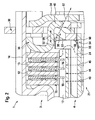
- FIGS. 1 . 2 . 3 . 4 . 11, 12 . 13 . 14 . 27, 28 In each case, a part of a drive train of a motor vehicle is shown in different views. Between a drive unit, in particular an internal combustion engine, from which a crankshaft originates, and a transmission, a wet-running dual clutch 1 is arranged in lamellar construction.
- the dual clutch 1 comprises a radially outer multi-disc clutch 3 and a radially inner multi-disc clutch 4, which is arranged in the axial direction overlapping the radially outer multi-disc clutch 3.
- the radially outer multi-plate clutch 3 comprises a disk set 11 with outer disks 12, 13, which are non-rotatably connected to an outer disk carrier 14.
- the disk set further comprises inner disks 15, 16 which are non-rotatably connected to an inner disk carrier 17.
- the radially inner multi-plate clutch 4 comprises a disk set 21, which, as can be seen in the in FIG. 3 illustrated embodiment, outer plates 22, 23 includes, which are rotatably connected to an outer disk carrier 24.
- the disk set 21 further comprises inner disks 25, 26 which are non-rotatably connected to an inner disk carrier 27.
- the outer disk carrier 14, which is also referred to as outer disk carrier, the radially outer multi-plate clutch 3 is rotatably connected by a connecting member 30 with the outer disk carrier 24, which is also referred to as outer disk carrier, the radially inner multi-plate clutch 4.
- the connecting part 30, which is also referred to as a carrying device, is formed substantially annular and is therefore also referred to as a support ring.
- the multi-plate clutch 3 is actuated by an actuating lever device 34.
- the actuating device 34 is coupled to the disk pack 11 with the interposition of a pressure transmission device 36.
- the pressure transmission device 36 is formed substantially annular and is therefore also referred to as a pressure ring 36.
- the pressure ring 36 is clamped in the axial direction between the disk set 11 and the actuating lever device 34.
- the pressure ring 36 has a plurality of at least partially extending in the axial direction finger 40, which, as indicated by an arrow 41, through through holes 38 which are recessed in the connecting part 30.
- the through-holes 38 are also referred to as finger windows.
- arrows 43 to 45 it is indicated that a cooling medium in the radial direction is passed through the plate packs 11, 21 in order to cool the slats.
- a wet clutch uses a special cooling medium, such as cooling oil, to dissipate the heat generated at the fins during operation.
- the medium must be led from a cooling circuit to the slats.
- friction plates friction linings are attached.
- the cooling oil flows between steel plates and friction plates, whereby a temperature exchange can take place. Grooves in the linings guide the oil from the radially inner multi-plate clutch 4 radially outward to the radially outer multi-plate clutch 3.
- the cooling medium mixes with the oil in the transmission sump. From here it is pumped to the radiator and from there back into the clutch.
- FIG. 1 is indicated by an arrow 48 that a part of the cooling medium escapes through the through holes or finger window 38 in the axial direction to the outside. This leads to poor pump efficiency and oil distribution.
- the through holes 38 or finger windows are sealed by a sealing device or sealing member.
- the sealing part or the sealing device preferably interacts with the pressure ring.
- any existing leakage gap can be minimized and the cooling can be optimized.
- the through holes or finger windows 38 are at least partially closed by the sealing means. As a result, the leakage can be significantly reduced. This in turn means that a weaker or smaller pump can be used, which has a positive effect on fuel consumption.
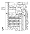
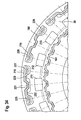
- a sealing device 50 is disposed in the region of the through holes 38.
- the sealing device 50 comprises a sealing ring 51, which essentially has the shape of a circular disk. Radially outward, the sealing ring 51 has an angled leg 52. Radially inside, the sealing ring 51 has noses or fingers 54, which engages or engage in a groove or grooves 55 which is recessed in the outer disk carrier 24 or are.
- An arrow 56 indicates that the main part of the cooling medium passes from the radially inner plate pack 21 to the radially outer plate pack 11.
- By a further arrow 57 is indicated that only a small leakage through the finger window 38 escapes.
- By a double arrow 58 it is indicated that the pressure ring 36 moves in an axial direction when the multi-disc clutch 3 is actuated.
- FIG. 3 it can be seen that the radially inner multi-plate clutch 4 is actuated by means of an actuating lever device 64. Between the actuating lever device 64 and the disk set 21, a pressure transmission device 66 is clamped. The pressure transmission device 66 is a closed pressure ring. By a crossed arrow 67 is indicated that no cooling medium can escape through the closed pressure ring 66.
- the outer disk carrier 24 is provided with an outer toothing 70, which would allow escape of oil in the axial direction. By a crossed arrow 72 it is indicated that the sealing device 50 reliably prevents escape of cooling medium in the axial direction through the through-holes 38.
- a transport safety function is integrated into the sealing device 50, which is also referred to as a sealing part.
- the sealing device 50 By engaging in the grooves 55 of the disk carrier 24 noses or fingers 54 of the sealing device 50 of the outer disk carrier 24 is securely held in position.
- the grooves issued hooks or holes can be provided.
- the transport lock according to the invention an unwanted axial displacement of the parts is reliably prevented.
- the sealing device 50 is stamped and formed from a sheet metal part.
- a sealing device 80 is installed, which is similar to the sealing device 50 of the preceding embodiment. However, that is at the in FIG. 4 illustrated embodiment, the end of the leg 52 in the radial direction between the inner disk carrier 17 and an end plate 81 is arranged. As a result, a sealing point 82 is created in a simple manner.
- sealing device 50 is shown in perspective. In FIG. 5 it can be seen that the sealing device 50 has a plurality of noses or fingers 54, 84, 85, 86.
- the angled leg 52 constitutes a sealing surface 52.
- FIG. 6 is an enlarged section of FIG. 5 shown.
- the pressure ring 36 comprises an annular body 90, which has a bent edge region 91.
- the pressure ring 36 may be formed of steel.
- the bent edge region 91 creates a centering surface.
- a sealing surface 93 is provided by a further bent edge region, so that the pressure ring 36 has a C-shaped or U-shaped cross-section.
- the pressure ring 36 has a plurality of curved fingers 95, 96.
- the fingers 95, 96 may have centering surfaces 98 or centering flanks that can be used for flank centering. By the deformed edge regions, the rigidity of the pressure ring 36 is increased.
- FIGS. 9 and 10 a further variant of the pressure ring 36 is shown.
- the in the FIGS. 9 and 10 shown pressure ring 36 comprises an annular body 100 with a bent or reshaped edge portion 101. Radially outside 101 teeth 102 are formed on the edge region, the flanks converge to the outside. The teeth 102 serve to center the pressure ring 36. 103, the sealing surface of the pressure ring 36 is designated. Furthermore, the pressure ring 36 has a plurality of curved fingers 105, 106.
- the sealing device is designed as a spring.
- the sealing part or the sealing device from a sheet, in particular a spring plate are punched and formed.
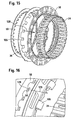
- FIGS. 11 and 12 a wet-running double clutch with a sealing device 110 is shown.
- the sealing device 110 comprises, viewed in cross-section, a U-shaped positioning portion 112 which extends around the radially inner edge region of the support ring 30 around.
- a circle 116 is highlighted that in the in FIG. 11 illustrated open state of the clutch, a gap between the free end 114 of the sealing device 110 and the pressure ring 36 is present.
- FIG. 12 the closed state of the coupling is shown.
- the gap is closed with the clutch closed at a point 118. That is, by the spring action of the sealing device 110, this is braced during the movement of the pressure ring 36 to close the clutch.
- the spring action of the sealing device 110 helps to open the coupling.
- the gap shown in the circle 116 also has a positive effect on the drag torque when the clutch is open because the cooling medium or cooling oil can escape through the gap.
- the in the FIGS. 11 and 12 illustrated sealing device 110 may, as in the previous embodiments, be equipped with noses, fingers or hooks.
- FIG. 13 a dual clutch with a sealing device 120 is shown, which has an L-shaped cross section with a contact portion 122.
- the contact portion 122 is arranged in the radial direction between the outer disk carrier 24 and the support ring 30. Between the free end 124 of the sealing device 120 and the pressure ring 36, a small gap is present.
- the sealing device 120 is designed as a spring. By a suitable spring bias, the gap between the free end 124 and the sealing device 120 and the pressure ring 36 is closed.
- FIGS. 15 to 20 is the assembly of the connecting part 30 with the outer disk carrier 24 of the radially inner multi-plate clutch 4 (see Figures 2 and 3 ) and the pressure ring 36 and the sealing device 50 shown in various views and assembly steps.
- a bayonet lock or a bayonet mount the connecting part 30, the pressure ring 36 and the outer disk carrier 24 are fixed by means of the sealing device 50 in the assembled state in the axial direction.
- FIG. 15 is indicated by an arrow 128 that the fingers 105 of the pressure ring 36 are passed through the finger window in the connecting part 30 during assembly.
- FIG. 16 it can be seen that the finger 105 is inserted through the finger window in the connecting part 30.
- an arrow 129 is in FIG. 16 indicated that the bent end 126 of the sealing device 50 is passed in the region of a tooth root on the internal toothing of the connecting part 30 in the axial direction.
- FIG. 17 it can be seen that the sealing device with the bent end 126, as indicated by an arrow 130, is rotated in the circumferential direction to engage with a tooth of the internal toothing of the connecting part 30.
- a bayonet-type connection is created.
- FIG. 18 is indicated by an arrow 132 that after generating the bayonet lock the outer disk carrier 24 is brought with an external toothing in engagement with the internal toothing of the connecting part 30.
- FIG. 19 it can be seen that the bent end 126 of the sealing device 50 is arranged between two teeth of the external toothing of the outer disk carrier 24.
- FIG. 20 it can be seen that a groove 135 issued between two teeth of the external toothing or of the toothing of the outer disk carrier 24 abuts against the bent end 126 of the sealing device 50 such that the bent end 126 is clamped between the connecting part 30 and the fluted groove 135 in the axial direction becomes.
- FIG. 21 the sealing device 50 is shown in perspective.
- FIG. 22 is a section of FIG. 21 shown enlarged.
- the sealing ring 51 a plurality of fingers or lugs 54 are angled radially inwardly. The ends of the noses or fingers 54 are bent at their end 126.
- FIG. 23 is the same section as in FIG. 22 illustrated according to another embodiment.
- the lugs 54 of the sealing device 50 can also be designed without a bent end.
- FIG. 24 the pressure ring 36 is shown in perspective.
- FIG. 25 is a section of FIG. 24 enlarged shown in section.
- the sealing surface or sealing surface 103 in the installed state of the pressure ring 36 faces the adjacent plate pack or the associated inner plate carrier.
- the ends of the fingers 105, 106 are curved radially inwardly. At the curved ends of the fingers 105, 106 comes in the installed state, the operating lever device to the plant.
- FIG. 26 is the same section as in FIG. 25 illustrated according to another embodiment. The same embodiment is also in the FIGS. 7 and 8 shown.
- the bent edge region 91 serves according to a first option for centering the pressure ring.
- the side surface 98 of the finger 96 may be used for centering. Therefore, the side surface is also referred to as centering surface 98.
- the sealing surface is designated 93.
- the pressure ring 36 for the spring design of the sealing device with a special shaped sealing surface 93; 103 equipped.
- the special deformation allows in a simple way that the spring-designed sealing device is braced only when the clutch is closed. In the open state of the clutch, a gap is released between the resiliently executed sealing device and the pressure ring, as in the Figures 11 and 13 is shown.
- a gap is released between the resiliently executed sealing device and the pressure ring, as in the Figures 11 and 13 is shown.
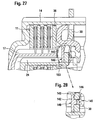
- a sealing device 140 according to another embodiment is shown both in the installed state and separately in different views.
- the sealing device 140 is designed according to a further aspect of the invention as a plastic part.
- the sealing device 140 is preferably designed so that it can be produced by injection molding.
- the sealing device 140 comprises a sealing ring or sealing ring 142 which essentially has the shape of a circular ring disk. Radially outwardly, the sealing ring 142 is integrally connected to a collar 143, which is preferably angled at right angles from the sealing ring 142.
- the collar 43 faces the disk set 11 of the radially outer multi-plate clutch and is arranged radially inside the pressure ring 36. At the same time, the collar 143 is arranged radially outside of the inner disk carrier 17 of the radially outer multi-plate clutch.
- snap hooks 145 extend from the sealing ring 142.
- the snap hook 145 can, as in FIG. 30 sees, from several, in particular four, Schnapphakensegmenten be formed.
- the snap hook 145 extends as shown in FIG. 28 sees through a through hole 146 which is recessed in the connecting part 30.
- the through hole 146 and the snap hook 145 are dimensioned and designed so that the snap hook 145 can be passed through the through hole 146 during assembly without damage.
- the prestressed ends of the snap hook 145 spread radially outwardly so that they engage behind the edge region of the through hole 146 on the side facing away from the sealing ring 142, that the sealing ring 142 in abutment the connecting part 30 is held.
- FIG. 29 it can be seen that three snap hooks 145, 147, 148 are evenly distributed over the circumference of the sealing device 140.
- the sealing surface of the sealing device 140 is designated.
- Radially inside, the sealing ring 142 has lugs or teeth 151, 152 which come to rest on elevations 153 of the outer disk carrier 24. The elevations 153 form an axial stop for the sealing ring 142.
- the outer disk carrier 14 of the radially outer multi-plate clutch is shown together with the connecting part 30 and the outer disk carrier 24 of the radially inner clutch in various views and representations.
- the outer disk carrier 14 comprises a toothed body 160 produced by roll forming.
- the toothing body 160 is deformed such that it has an inner toothing radially inward and an outer toothing radially outward.
- the outer disk carrier 24 of the radially inner disk clutch comprises a similar gear body 161, which, however, has a smaller diameter than the gear body 160.
- the toothing of the outer disk carrier 24 is denoted by 164.
- the toothing 164 comprises an external toothing with teeth 165, 166, which are distributed uniformly over the circumference of the outer disk carrier 24.
- the external toothing of the outer disk carrier 24 engages with an internal toothing 168 which is formed radially inward on the connecting part 30.
- the internal teeth 168 include teeth 169, 170 which engage in the interdental spaces of the external teeth of the outer disk carrier 24.
- the connecting part 30 comprises a plurality of finger windows 171 to 173 which are arranged uniformly over a circumference or pitch circle of the connecting part 30.
- the finger windows 171 to 173 allow the passage of the finger formed on the pressure ring.
- web windows 181 to 183 are recessed in the connecting part 30.
- Each web window 181 to 183 is assigned a finger window 171 to 173.
- Each web window 181 to 183 is bounded in the circumferential direction by two webs 185, 186 each, which extend in the radial direction of the connecting part 30.
- the web windows 181 to 183 serve to create a non-rotatable, positive connection between the connecting part 30 and the outer disk carrier 14.
- the outer disk carrier 14 has a plurality of recesses 188, 190, between each of which an engagement element 189 is formed.
- Each web window 181 to 183 is assigned an engagement element 189 in each case.
- the recess 190 is bounded circumferentially by two opposing side surfaces 191, 192 of adjacent engagement elements 189.
- On the side surfaces 191, 192 of the recess 190 come in the assembled state with the connecting part 30 side surfaces 193, 194 in Appendix, which limit the associated web window 181, 182 in the connecting part 30. In the assembled state engages in each case an engagement element 189 in the associated web window 182.
- the recesses 188, 190 are dimensioned so that a part of the associated tooth heads 196, 197 of the teeth 164 stops.
- FIGS. 31 to 33 It is shown how the outer disk carrier 24 of the inner clutch is suspended in the outer disk carrier 14 of the outer clutch.
- the separate connecting part 30 provides the advantage that the toothed bodies 160, 161 of the two outer disk carriers can each be manufactured by roll forming.
- connection part 30 has, inter alia, the function of directing the torque from the outer disk carrier 14, which is preferably non-rotatably connected to a crankshaft of an internal combustion engine, to the gear body 161 of the outer disk carrier 24 of the inner clutch.
- the connecting part 30 is connected by a plug connection with the outer disk carrier 14.
- the transmission of the torque from the connecting part 30 to the toothing body 161 takes place on the flanks of the teeth 169, 170 of the internal toothing of the connecting part 30 on the flanks of the teeth 165, 166 of the external toothing of the toothed body 161.
- the connecting part 30 has the task or function to support the actuating force of the radially inner multi-plate clutch on the outer disk carrier 14 of the outer shaft coupling.
- grooves 201, 202 issued from the toothing body 161 serve as an axial stop of the connecting part 30 on the toothed body 161.
- the actuating force of the inner multi-disc clutch is introduced into the connecting part 30 via the issued grooves 201, 202.
- the webs 185, 186 of the connecting part 30 are in the axial direction of stop surfaces 203, 204 of the recesses 188, 190 in order to forward the actuating force.
- it is advantageous that the issued grooves 201, 202 are arranged symmetrically to the center of the webs 185, 186. This ensures that the actuating force is not passed over a narrow residual cross section 205 between the internal teeth 168 and the finger windows 171, 172, 173 for the fingers of the pressure ring.
- the teeth of the outer disk carrier 14 of the outer multi-plate clutch and the teeth on the toothing body 161 of the outer disk carrier 24 of the inner multi-plate clutch have the same number of teeth.
- the number of bridge windows and the number of finger windows correspond to exactly half of the number of teeth.
- the connecting part 30 engages around the outer disk carrier 14 and radially supports the outer tooth heads 196, 197.
- FIG. 34 is a further embodiment of the connecting part 30 with finger windows 211 to 213 and toothed windows 215, 216 shown.
- the toothed windows 215, 216 each have an outer tooth 221 extending radially inwardly at the connecting portion 30 and two inner teeth 222, 223 extending radially outward at the connecting portion 30.
- the inner teeth 222, 223 engage in the internal toothing of the toothing body 160.
- the external tooth 221 engages in the external toothing of the toothing body 160.
- the torque transmission takes place both via the outer teeth 221 and via the inner teeth 222, 223.
- the inner teeth 222, 223 take on their flanks at the same time the centrifugal force.
- FIG. 34 is a further embodiment of the connecting part 30 with finger windows 211 to 213 and toothed windows 215, 216 shown.
- the toothed windows 215, 216 each have an outer tooth 221 extending radially inwardly at the connecting portion 30 and two inner teeth 222, 223
- tooth windows 215, 216 are each two flared grooves 225, 227 and 226, 228 visible, which are exposed from the gear body 160.
Landscapes
- Engineering & Computer Science (AREA)
- General Engineering & Computer Science (AREA)
- Mechanical Engineering (AREA)
- Mechanical Operated Clutches (AREA)
Applications Claiming Priority (1)
| Application Number | Priority Date | Filing Date | Title |
|---|---|---|---|
| DE102006059669 | 2006-12-18 |
Publications (3)
| Publication Number | Publication Date |
|---|---|
| EP1936220A2 true EP1936220A2 (fr) | 2008-06-25 |
| EP1936220A3 EP1936220A3 (fr) | 2010-10-13 |
| EP1936220B1 EP1936220B1 (fr) | 2012-07-11 |
Family
ID=39361345
Family Applications (1)
| Application Number | Title | Priority Date | Filing Date |
|---|---|---|---|
| EP07022377A Not-in-force EP1936220B1 (fr) | 2006-12-18 | 2007-11-19 | Dispositif de transmission de couple |
Country Status (2)
| Country | Link |
|---|---|
| US (1) | US7874415B2 (fr) |
| EP (1) | EP1936220B1 (fr) |
Cited By (4)
| Publication number | Priority date | Publication date | Assignee | Title |
|---|---|---|---|---|
| CN105317867A (zh) * | 2014-07-25 | 2016-02-10 | 大众汽车有限公司 | 离合器 |
| CN106870589A (zh) * | 2015-12-14 | 2017-06-20 | 舍弗勒技术股份两合公司 | 离合器片支架连接结构 |
| WO2018104548A1 (fr) * | 2016-12-09 | 2018-06-14 | Fischer & Kaufmann Gmbh & Co. Kg | Support de lamelles |
| FR3081951A1 (fr) * | 2018-05-30 | 2019-12-06 | Valeo Embrayages | Dispositif comportant une pluralite d'embrayages |
Families Citing this family (6)
| Publication number | Priority date | Publication date | Assignee | Title |
|---|---|---|---|---|
| DE102009006647B4 (de) * | 2008-02-04 | 2019-01-31 | Schaeffler Technologies AG & Co. KG | Doppelkupplungsanordnung |
| US8387729B2 (en) | 2011-03-10 | 2013-03-05 | Caterpillar Inc. | Machine having electrical power system and centered drive coupling for same |
| DE102013111877B4 (de) | 2013-10-28 | 2017-09-07 | Gkn Automotive Ltd. | Lamellenträger mit mehreren radialen Durchbrüchen zur Kühlung eines Lamellenpakets, Lamellenkupplung und Verfahren zur Herstellung eines Lamellenträgers |
| DE102015204822A1 (de) * | 2014-03-27 | 2015-10-01 | Schaeffler Technologies AG & Co. KG | Rotationsbaugruppe mit mechanischer Steckverbindung sowie Drehmomentübertragungseinrichtung |
| DE102016216322A1 (de) * | 2015-09-01 | 2017-03-02 | Schaeffler Technologies AG & Co. KG | Kupplungseinrichtung |
| US9915332B1 (en) * | 2016-10-26 | 2018-03-13 | Schaeffler Technologies AG & Co. KG | Motor vehicle clutch assembly including shock absorber for smoothing clutch engagement |
Family Cites Families (5)
| Publication number | Priority date | Publication date | Assignee | Title |
|---|---|---|---|---|
| DE10323515A1 (de) * | 2003-05-24 | 2004-12-23 | Dr.Ing.H.C. F. Porsche Ag | Kupplungsvorrichtung und Verfahren zum Betreiben einer Lamellenkupplung |
| DE102005063529B4 (de) * | 2004-06-21 | 2020-01-16 | Schaeffler Technologies AG & Co. KG | Nasslaufende Doppelkupplung in Lamellenbauweise |
| EP1610016B2 (fr) * | 2004-06-21 | 2011-11-16 | Schaeffler Technologies AG & Co. KG | Agencement de transmission du couple |
| EP1645765B1 (fr) * | 2004-10-06 | 2018-09-12 | BorgWarner, Inc. | Ensemble de transmission |
| DE112007000452A5 (de) * | 2006-04-04 | 2008-11-27 | Luk Lamellen Und Kupplungsbau Beteiligungs Kg | Radiale Stromungskammer für Kupplungen in einer Kupplungsbaugruppe |
-
2007
- 2007-11-19 EP EP07022377A patent/EP1936220B1/fr not_active Not-in-force
- 2007-12-13 US US12/001,808 patent/US7874415B2/en not_active Expired - Fee Related
Non-Patent Citations (1)
| Title |
|---|
| None |
Cited By (8)
| Publication number | Priority date | Publication date | Assignee | Title |
|---|---|---|---|---|
| CN105317867A (zh) * | 2014-07-25 | 2016-02-10 | 大众汽车有限公司 | 离合器 |
| CN106870589A (zh) * | 2015-12-14 | 2017-06-20 | 舍弗勒技术股份两合公司 | 离合器片支架连接结构 |
| WO2018104548A1 (fr) * | 2016-12-09 | 2018-06-14 | Fischer & Kaufmann Gmbh & Co. Kg | Support de lamelles |
| CN110073122A (zh) * | 2016-12-09 | 2019-07-30 | 雨果·毕舍匹克 | 盘片载体 |
| KR20190093589A (ko) * | 2016-12-09 | 2019-08-09 | 후고 비쇼핑크 | 디스크 캐리어 |
| CN110073122B (zh) * | 2016-12-09 | 2020-10-30 | 雨果·毕舍匹克 | 用于制造盘片载体的方法 |
| KR102479691B1 (ko) | 2016-12-09 | 2022-12-20 | 후고 비쇼핑크 | 디스크 캐리어 |
| FR3081951A1 (fr) * | 2018-05-30 | 2019-12-06 | Valeo Embrayages | Dispositif comportant une pluralite d'embrayages |
Also Published As
| Publication number | Publication date |
|---|---|
| EP1936220B1 (fr) | 2012-07-11 |
| EP1936220A3 (fr) | 2010-10-13 |
| US20080142330A1 (en) | 2008-06-19 |
| US7874415B2 (en) | 2011-01-25 |
Similar Documents
| Publication | Publication Date | Title |
|---|---|---|
| EP1936220B1 (fr) | Dispositif de transmission de couple | |
| DE102007055151A1 (de) | Drehmomentübertragungseinrichtung | |
| EP1422430B1 (fr) | Transmission de véhicule avec embrayage à multi-disques | |
| EP1645765B1 (fr) | Ensemble de transmission | |
| DE112012001892B4 (de) | Überbrückungsvorrichtung für einen Drehmomentwandler | |
| EP2014943B1 (fr) | Embrayage, de préférence embrayage double pour un véhicule automobile | |
| DE102013226393B4 (de) | Reibscheibe für eine Kupplungseinrichtung, Kupplungseinrichtung sowie Drehmomentübertragungseinrichtung | |
| DE10131766A1 (de) | Kombination zum Aufbauen eines Antriebsstrangs mit einer Antriebseinheit, einer als vollständige Baueinheit montierbaren Mehrfach-Kupplungseinheit, einem Getriebe sowie ggf. einer Torsionsschwingungsdämpferanordnung, sowie entsprechende Kupplungsbaueinheit | |
| DE102007027120B4 (de) | Kupplung mit Stützelement für ein Lamellenpaket | |
| DE19905373A1 (de) | Reibungskupplung und Anpreßhebelanordnung für eine Reibungskupplung | |
| DE102012008779B4 (de) | Kupplung | |
| EP1693588B1 (fr) | Arrangement pour le support axial de deux éléments rotatifs. | |
| DE102010044379A1 (de) | Kupplung | |
| DE102016202179B4 (de) | Kupplungseinrichtung | |
| WO2020169140A1 (fr) | Système d'embrayage compact à système support de disques | |
| EP1783388B1 (fr) | Dispositif d'embrayage à disques multiples | |
| DE102006062833C5 (de) | Drehmomentübertragungseinrichtung | |
| DE102007027121A1 (de) | Doppelkupplung | |
| WO2009112243A2 (fr) | Embrayage à disques humide | |
| DE102013209761A1 (de) | Anordnung zum Beabstanden von Lamellen eines Schaltelementes | |
| EP3927991B1 (fr) | Système d'embrayage compact doté d'un corps d'appui | |
| DE102009006648A1 (de) | Lamellenkupplung, insbesondere Doppellamellenkupplung | |
| WO2009033937A1 (fr) | Agencement pour le soutien axial d'un disque terminal d'un groupe de disques au moyen d'une bague élastique | |
| DE102009060351A1 (de) | Kupplung | |
| DE102008022865A1 (de) | Kupplungsvorrichtung mit einer eingangsseitigen Kopplungseinrichtung und Verwendung eines Zahnrades mit zwei Teilrädern zur Ausbildung einer Steckverzahnung |
Legal Events
| Date | Code | Title | Description |
|---|---|---|---|
| PUAI | Public reference made under article 153(3) epc to a published international application that has entered the european phase |
Free format text: ORIGINAL CODE: 0009012 |
|
| AK | Designated contracting states |
Kind code of ref document: A2 Designated state(s): AT BE BG CH CY CZ DE DK EE ES FI FR GB GR HU IE IS IT LI LT LU LV MC MT NL PL PT RO SE SI SK TR |
|
| AX | Request for extension of the european patent |
Extension state: AL BA HR MK RS |
|
| RIC1 | Information provided on ipc code assigned before grant |
Ipc: F16D 13/72 20060101ALI20100128BHEP Ipc: F16D 21/06 20060101ALI20100128BHEP Ipc: F16D 13/52 20060101AFI20080516BHEP Ipc: F16D 13/58 20060101ALI20100128BHEP |
|
| PUAL | Search report despatched |
Free format text: ORIGINAL CODE: 0009013 |
|
| AK | Designated contracting states |
Kind code of ref document: A3 Designated state(s): AT BE BG CH CY CZ DE DK EE ES FI FR GB GR HU IE IS IT LI LT LU LV MC MT NL PL PT RO SE SI SK TR |
|
| AX | Request for extension of the european patent |
Extension state: AL BA HR MK RS |
|
| RAP1 | Party data changed (applicant data changed or rights of an application transferred) |
Owner name: SCHAEFFLER TECHNOLOGIES GMBH & CO. KG |
|
| 17P | Request for examination filed |
Effective date: 20110413 |
|
| AKX | Designation fees paid |
Designated state(s): AT BE BG CH CY CZ DE DK EE ES FI FR GB GR HU IE IS IT LI LT LU LV MC MT NL PL PT RO SE SI SK TR |
|
| GRAP | Despatch of communication of intention to grant a patent |
Free format text: ORIGINAL CODE: EPIDOSNIGR1 |
|
| RAP1 | Party data changed (applicant data changed or rights of an application transferred) |
Owner name: SCHAEFFLER TECHNOLOGIES AG & CO. KG |
|
| GRAS | Grant fee paid |
Free format text: ORIGINAL CODE: EPIDOSNIGR3 |
|
| GRAA | (expected) grant |
Free format text: ORIGINAL CODE: 0009210 |
|
| AK | Designated contracting states |
Kind code of ref document: B1 Designated state(s): AT BE BG CH CY CZ DE DK EE ES FI FR GB GR HU IE IS IT LI LT LU LV MC MT NL PL PT RO SE SI SK TR |
|
| REG | Reference to a national code |
Ref country code: GB Ref legal event code: FG4D Free format text: NOT ENGLISH |
|
| REG | Reference to a national code |
Ref country code: CH Ref legal event code: EP |
|
| REG | Reference to a national code |
Ref country code: AT Ref legal event code: REF Ref document number: 566308 Country of ref document: AT Kind code of ref document: T Effective date: 20120715 |
|
| REG | Reference to a national code |
Ref country code: IE Ref legal event code: FG4D Free format text: LANGUAGE OF EP DOCUMENT: GERMAN |
|
| REG | Reference to a national code |
Ref country code: DE Ref legal event code: R096 Ref document number: 502007010182 Country of ref document: DE Effective date: 20120906 |
|
| REG | Reference to a national code |
Ref country code: NL Ref legal event code: VDEP Effective date: 20120711 |
|
| REG | Reference to a national code |
Ref country code: LT Ref legal event code: MG4D Effective date: 20120711 |
|
| PG25 | Lapsed in a contracting state [announced via postgrant information from national office to epo] |
Ref country code: LT Free format text: LAPSE BECAUSE OF FAILURE TO SUBMIT A TRANSLATION OF THE DESCRIPTION OR TO PAY THE FEE WITHIN THE PRESCRIBED TIME-LIMIT Effective date: 20120711 Ref country code: FI Free format text: LAPSE BECAUSE OF FAILURE TO SUBMIT A TRANSLATION OF THE DESCRIPTION OR TO PAY THE FEE WITHIN THE PRESCRIBED TIME-LIMIT Effective date: 20120711 Ref country code: CY Free format text: LAPSE BECAUSE OF FAILURE TO SUBMIT A TRANSLATION OF THE DESCRIPTION OR TO PAY THE FEE WITHIN THE PRESCRIBED TIME-LIMIT Effective date: 20120711 Ref country code: IS Free format text: LAPSE BECAUSE OF FAILURE TO SUBMIT A TRANSLATION OF THE DESCRIPTION OR TO PAY THE FEE WITHIN THE PRESCRIBED TIME-LIMIT Effective date: 20121111 |
|
| PG25 | Lapsed in a contracting state [announced via postgrant information from national office to epo] |
Ref country code: LV Free format text: LAPSE BECAUSE OF FAILURE TO SUBMIT A TRANSLATION OF THE DESCRIPTION OR TO PAY THE FEE WITHIN THE PRESCRIBED TIME-LIMIT Effective date: 20120711 Ref country code: GR Free format text: LAPSE BECAUSE OF FAILURE TO SUBMIT A TRANSLATION OF THE DESCRIPTION OR TO PAY THE FEE WITHIN THE PRESCRIBED TIME-LIMIT Effective date: 20121012 Ref country code: SI Free format text: LAPSE BECAUSE OF FAILURE TO SUBMIT A TRANSLATION OF THE DESCRIPTION OR TO PAY THE FEE WITHIN THE PRESCRIBED TIME-LIMIT Effective date: 20120711 Ref country code: PL Free format text: LAPSE BECAUSE OF FAILURE TO SUBMIT A TRANSLATION OF THE DESCRIPTION OR TO PAY THE FEE WITHIN THE PRESCRIBED TIME-LIMIT Effective date: 20120711 Ref country code: PT Free format text: LAPSE BECAUSE OF FAILURE TO SUBMIT A TRANSLATION OF THE DESCRIPTION OR TO PAY THE FEE WITHIN THE PRESCRIBED TIME-LIMIT Effective date: 20121112 Ref country code: SE Free format text: LAPSE BECAUSE OF FAILURE TO SUBMIT A TRANSLATION OF THE DESCRIPTION OR TO PAY THE FEE WITHIN THE PRESCRIBED TIME-LIMIT Effective date: 20120711 |
|
| PG25 | Lapsed in a contracting state [announced via postgrant information from national office to epo] |
Ref country code: NL Free format text: LAPSE BECAUSE OF FAILURE TO SUBMIT A TRANSLATION OF THE DESCRIPTION OR TO PAY THE FEE WITHIN THE PRESCRIBED TIME-LIMIT Effective date: 20120711 |
|
| PG25 | Lapsed in a contracting state [announced via postgrant information from national office to epo] |
Ref country code: RO Free format text: LAPSE BECAUSE OF FAILURE TO SUBMIT A TRANSLATION OF THE DESCRIPTION OR TO PAY THE FEE WITHIN THE PRESCRIBED TIME-LIMIT Effective date: 20120711 Ref country code: DK Free format text: LAPSE BECAUSE OF FAILURE TO SUBMIT A TRANSLATION OF THE DESCRIPTION OR TO PAY THE FEE WITHIN THE PRESCRIBED TIME-LIMIT Effective date: 20120711 Ref country code: ES Free format text: LAPSE BECAUSE OF FAILURE TO SUBMIT A TRANSLATION OF THE DESCRIPTION OR TO PAY THE FEE WITHIN THE PRESCRIBED TIME-LIMIT Effective date: 20121022 Ref country code: EE Free format text: LAPSE BECAUSE OF FAILURE TO SUBMIT A TRANSLATION OF THE DESCRIPTION OR TO PAY THE FEE WITHIN THE PRESCRIBED TIME-LIMIT Effective date: 20120711 Ref country code: CZ Free format text: LAPSE BECAUSE OF FAILURE TO SUBMIT A TRANSLATION OF THE DESCRIPTION OR TO PAY THE FEE WITHIN THE PRESCRIBED TIME-LIMIT Effective date: 20120711 |
|
| PLBE | No opposition filed within time limit |
Free format text: ORIGINAL CODE: 0009261 |
|
| STAA | Information on the status of an ep patent application or granted ep patent |
Free format text: STATUS: NO OPPOSITION FILED WITHIN TIME LIMIT |
|
| BERE | Be: lapsed |
Owner name: SCHAEFFLER TECHNOLOGIES A.G. & CO. KG Effective date: 20121130 |
|
| PG25 | Lapsed in a contracting state [announced via postgrant information from national office to epo] |
Ref country code: IT Free format text: LAPSE BECAUSE OF FAILURE TO SUBMIT A TRANSLATION OF THE DESCRIPTION OR TO PAY THE FEE WITHIN THE PRESCRIBED TIME-LIMIT Effective date: 20120711 Ref country code: SK Free format text: LAPSE BECAUSE OF FAILURE TO SUBMIT A TRANSLATION OF THE DESCRIPTION OR TO PAY THE FEE WITHIN THE PRESCRIBED TIME-LIMIT Effective date: 20120711 |
|
| 26N | No opposition filed |
Effective date: 20130412 |
|
| REG | Reference to a national code |
Ref country code: CH Ref legal event code: PL |
|
| GBPC | Gb: european patent ceased through non-payment of renewal fee |
Effective date: 20121119 |
|
| PG25 | Lapsed in a contracting state [announced via postgrant information from national office to epo] |
Ref country code: LI Free format text: LAPSE BECAUSE OF NON-PAYMENT OF DUE FEES Effective date: 20121130 Ref country code: BG Free format text: LAPSE BECAUSE OF FAILURE TO SUBMIT A TRANSLATION OF THE DESCRIPTION OR TO PAY THE FEE WITHIN THE PRESCRIBED TIME-LIMIT Effective date: 20121011 Ref country code: CH Free format text: LAPSE BECAUSE OF NON-PAYMENT OF DUE FEES Effective date: 20121130 |
|
| REG | Reference to a national code |
Ref country code: DE Ref legal event code: R097 Ref document number: 502007010182 Country of ref document: DE Effective date: 20130412 |
|
| REG | Reference to a national code |
Ref country code: IE Ref legal event code: MM4A |
|
| PG25 | Lapsed in a contracting state [announced via postgrant information from national office to epo] |
Ref country code: BE Free format text: LAPSE BECAUSE OF NON-PAYMENT OF DUE FEES Effective date: 20121130 |
|
| PG25 | Lapsed in a contracting state [announced via postgrant information from national office to epo] |
Ref country code: IE Free format text: LAPSE BECAUSE OF NON-PAYMENT OF DUE FEES Effective date: 20121119 |
|
| PG25 | Lapsed in a contracting state [announced via postgrant information from national office to epo] |
Ref country code: GB Free format text: LAPSE BECAUSE OF NON-PAYMENT OF DUE FEES Effective date: 20121119 Ref country code: MT Free format text: LAPSE BECAUSE OF FAILURE TO SUBMIT A TRANSLATION OF THE DESCRIPTION OR TO PAY THE FEE WITHIN THE PRESCRIBED TIME-LIMIT Effective date: 20120711 |
|
| REG | Reference to a national code |
Ref country code: AT Ref legal event code: MM01 Ref document number: 566308 Country of ref document: AT Kind code of ref document: T Effective date: 20121130 |
|
| PG25 | Lapsed in a contracting state [announced via postgrant information from national office to epo] |
Ref country code: AT Free format text: LAPSE BECAUSE OF NON-PAYMENT OF DUE FEES Effective date: 20121130 |
|
| REG | Reference to a national code |
Ref country code: DE Ref legal event code: R081 Ref document number: 502007010182 Country of ref document: DE Owner name: SCHAEFFLER TECHNOLOGIES AG & CO. KG, DE Free format text: FORMER OWNER: SCHAEFFLER TECHNOLOGIES AG & CO. KG, 91074 HERZOGENAURACH, DE Effective date: 20140213 Ref country code: DE Ref legal event code: R081 Ref document number: 502007010182 Country of ref document: DE Owner name: SCHAEFFLER TECHNOLOGIES GMBH & CO. KG, DE Free format text: FORMER OWNER: SCHAEFFLER TECHNOLOGIES AG & CO. KG, 91074 HERZOGENAURACH, DE Effective date: 20140213 |
|
| PG25 | Lapsed in a contracting state [announced via postgrant information from national office to epo] |
Ref country code: MC Free format text: LAPSE BECAUSE OF NON-PAYMENT OF DUE FEES Effective date: 20121130 Ref country code: TR Free format text: LAPSE BECAUSE OF FAILURE TO SUBMIT A TRANSLATION OF THE DESCRIPTION OR TO PAY THE FEE WITHIN THE PRESCRIBED TIME-LIMIT Effective date: 20120711 |
|
| PG25 | Lapsed in a contracting state [announced via postgrant information from national office to epo] |
Ref country code: LU Free format text: LAPSE BECAUSE OF NON-PAYMENT OF DUE FEES Effective date: 20121119 |
|
| PG25 | Lapsed in a contracting state [announced via postgrant information from national office to epo] |
Ref country code: HU Free format text: LAPSE BECAUSE OF FAILURE TO SUBMIT A TRANSLATION OF THE DESCRIPTION OR TO PAY THE FEE WITHIN THE PRESCRIBED TIME-LIMIT Effective date: 20071119 |
|
| REG | Reference to a national code |
Ref country code: DE Ref legal event code: R081 Ref document number: 502007010182 Country of ref document: DE Owner name: SCHAEFFLER TECHNOLOGIES AG & CO. KG, DE Free format text: FORMER OWNER: SCHAEFFLER TECHNOLOGIES GMBH & CO. KG, 91074 HERZOGENAURACH, DE Effective date: 20150223 |
|
| REG | Reference to a national code |
Ref country code: FR Ref legal event code: PLFP Year of fee payment: 9 |
|
| REG | Reference to a national code |
Ref country code: FR Ref legal event code: PLFP Year of fee payment: 10 |
|
| REG | Reference to a national code |
Ref country code: FR Ref legal event code: PLFP Year of fee payment: 11 |
|
| PGFP | Annual fee paid to national office [announced via postgrant information from national office to epo] |
Ref country code: FR Payment date: 20211122 Year of fee payment: 15 |
|
| PGFP | Annual fee paid to national office [announced via postgrant information from national office to epo] |
Ref country code: DE Payment date: 20220119 Year of fee payment: 15 |
|
| REG | Reference to a national code |
Ref country code: DE Ref legal event code: R119 Ref document number: 502007010182 Country of ref document: DE |
|
| P01 | Opt-out of the competence of the unified patent court (upc) registered |
Effective date: 20230522 |
|
| PG25 | Lapsed in a contracting state [announced via postgrant information from national office to epo] |
Ref country code: DE Free format text: LAPSE BECAUSE OF NON-PAYMENT OF DUE FEES Effective date: 20230601 |
|
| PG25 | Lapsed in a contracting state [announced via postgrant information from national office to epo] |
Ref country code: FR Free format text: LAPSE BECAUSE OF NON-PAYMENT OF DUE FEES Effective date: 20221130 |