EP1936246B2 - Bande en mousse et sa méthode de fabrication - Google Patents
Bande en mousse et sa méthode de fabrication Download PDFInfo
- Publication number
- EP1936246B2 EP1936246B2 EP20060026192 EP06026192A EP1936246B2 EP 1936246 B2 EP1936246 B2 EP 1936246B2 EP 20060026192 EP20060026192 EP 20060026192 EP 06026192 A EP06026192 A EP 06026192A EP 1936246 B2 EP1936246 B2 EP 1936246B2
- Authority
- EP
- European Patent Office
- Prior art keywords
- tape
- film
- flexible foam
- sealing
- sealing tape
- Prior art date
- Legal status (The legal status is an assumption and is not a legal conclusion. Google has not performed a legal analysis and makes no representation as to the accuracy of the status listed.)
- Active
Links
Images
Classifications
-
- F—MECHANICAL ENGINEERING; LIGHTING; HEATING; WEAPONS; BLASTING
- F16—ENGINEERING ELEMENTS AND UNITS; GENERAL MEASURES FOR PRODUCING AND MAINTAINING EFFECTIVE FUNCTIONING OF MACHINES OR INSTALLATIONS; THERMAL INSULATION IN GENERAL
- F16J—PISTONS; CYLINDERS; SEALINGS
- F16J15/00—Sealings
- F16J15/02—Sealings between relatively-stationary surfaces
- F16J15/021—Sealings between relatively-stationary surfaces with elastic packing
- F16J15/022—Sealings between relatively-stationary surfaces with elastic packing characterised by structure or material
-
- E—FIXED CONSTRUCTIONS
- E04—BUILDING
- E04B—GENERAL BUILDING CONSTRUCTIONS; WALLS, e.g. PARTITIONS; ROOFS; FLOORS; CEILINGS; INSULATION OR OTHER PROTECTION OF BUILDINGS
- E04B1/00—Constructions in general; Structures which are not restricted either to walls, e.g. partitions, or floors or ceilings or roofs
- E04B1/62—Insulation or other protection; Elements or use of specified material therefor
- E04B1/66—Sealings
- E04B1/68—Sealings of joints, e.g. expansion joints
- E04B1/6812—Compressable seals of solid form
-
- E—FIXED CONSTRUCTIONS
- E06—DOORS, WINDOWS, SHUTTERS, OR ROLLER BLINDS IN GENERAL; LADDERS
- E06B—FIXED OR MOVABLE CLOSURES FOR OPENINGS IN BUILDINGS, VEHICLES, FENCES OR LIKE ENCLOSURES IN GENERAL, e.g. DOORS, WINDOWS, BLINDS, GATES
- E06B1/00—Border constructions of openings in walls, floors, or ceilings; Frames to be rigidly mounted in such openings
- E06B1/62—Tightening or covering joints between the border of openings and the frame or between contiguous frames
-
- E—FIXED CONSTRUCTIONS
- E06—DOORS, WINDOWS, SHUTTERS, OR ROLLER BLINDS IN GENERAL; LADDERS
- E06B—FIXED OR MOVABLE CLOSURES FOR OPENINGS IN BUILDINGS, VEHICLES, FENCES OR LIKE ENCLOSURES IN GENERAL, e.g. DOORS, WINDOWS, BLINDS, GATES
- E06B7/00—Special arrangements or measures in connection with doors or windows
- E06B7/16—Sealing arrangements on wings or parts co-operating with the wings
- E06B7/22—Sealing arrangements on wings or parts co-operating with the wings by means of elastic edgings, e.g. elastic rubber tubes; by means of resilient edgings, e.g. felt or plush strips, resilient metal strips
- E06B7/23—Plastic, sponge rubber, or like strips or tubes
-
- F—MECHANICAL ENGINEERING; LIGHTING; HEATING; WEAPONS; BLASTING
- F16—ENGINEERING ELEMENTS AND UNITS; GENERAL MEASURES FOR PRODUCING AND MAINTAINING EFFECTIVE FUNCTIONING OF MACHINES OR INSTALLATIONS; THERMAL INSULATION IN GENERAL
- F16J—PISTONS; CYLINDERS; SEALINGS
- F16J15/00—Sealings
- F16J15/02—Sealings between relatively-stationary surfaces
- F16J15/06—Sealings between relatively-stationary surfaces with solid packing compressed between sealing surfaces
- F16J15/068—Sealings between relatively-stationary surfaces with solid packing compressed between sealing surfaces the packing swelling under working conditions
-
- E—FIXED CONSTRUCTIONS
- E06—DOORS, WINDOWS, SHUTTERS, OR ROLLER BLINDS IN GENERAL; LADDERS
- E06B—FIXED OR MOVABLE CLOSURES FOR OPENINGS IN BUILDINGS, VEHICLES, FENCES OR LIKE ENCLOSURES IN GENERAL, e.g. DOORS, WINDOWS, BLINDS, GATES
- E06B1/00—Border constructions of openings in walls, floors, or ceilings; Frames to be rigidly mounted in such openings
- E06B1/62—Tightening or covering joints between the border of openings and the frame or between contiguous frames
- E06B2001/626—Tightening or covering joints between the border of openings and the frame or between contiguous frames comprising expanding foam strips
-
- Y—GENERAL TAGGING OF NEW TECHNOLOGICAL DEVELOPMENTS; GENERAL TAGGING OF CROSS-SECTIONAL TECHNOLOGIES SPANNING OVER SEVERAL SECTIONS OF THE IPC; TECHNICAL SUBJECTS COVERED BY FORMER USPC CROSS-REFERENCE ART COLLECTIONS [XRACs] AND DIGESTS
- Y10—TECHNICAL SUBJECTS COVERED BY FORMER USPC
- Y10T—TECHNICAL SUBJECTS COVERED BY FORMER US CLASSIFICATION
- Y10T156/00—Adhesive bonding and miscellaneous chemical manufacture
- Y10T156/10—Methods of surface bonding and/or assembly therefor
- Y10T156/1052—Methods of surface bonding and/or assembly therefor with cutting, punching, tearing or severing
-
- Y—GENERAL TAGGING OF NEW TECHNOLOGICAL DEVELOPMENTS; GENERAL TAGGING OF CROSS-SECTIONAL TECHNOLOGIES SPANNING OVER SEVERAL SECTIONS OF THE IPC; TECHNICAL SUBJECTS COVERED BY FORMER USPC CROSS-REFERENCE ART COLLECTIONS [XRACs] AND DIGESTS
- Y10—TECHNICAL SUBJECTS COVERED BY FORMER USPC
- Y10T—TECHNICAL SUBJECTS COVERED BY FORMER US CLASSIFICATION
- Y10T428/00—Stock material or miscellaneous articles
- Y10T428/14—Layer or component removable to expose adhesive
-
- Y—GENERAL TAGGING OF NEW TECHNOLOGICAL DEVELOPMENTS; GENERAL TAGGING OF CROSS-SECTIONAL TECHNOLOGIES SPANNING OVER SEVERAL SECTIONS OF THE IPC; TECHNICAL SUBJECTS COVERED BY FORMER USPC CROSS-REFERENCE ART COLLECTIONS [XRACs] AND DIGESTS
- Y10—TECHNICAL SUBJECTS COVERED BY FORMER USPC
- Y10T—TECHNICAL SUBJECTS COVERED BY FORMER US CLASSIFICATION
- Y10T428/00—Stock material or miscellaneous articles
- Y10T428/24—Structurally defined web or sheet [e.g., overall dimension, etc.]
- Y10T428/2419—Fold at edge
-
- Y—GENERAL TAGGING OF NEW TECHNOLOGICAL DEVELOPMENTS; GENERAL TAGGING OF CROSS-SECTIONAL TECHNOLOGIES SPANNING OVER SEVERAL SECTIONS OF THE IPC; TECHNICAL SUBJECTS COVERED BY FORMER USPC CROSS-REFERENCE ART COLLECTIONS [XRACs] AND DIGESTS
- Y10—TECHNICAL SUBJECTS COVERED BY FORMER USPC
- Y10T—TECHNICAL SUBJECTS COVERED BY FORMER US CLASSIFICATION
- Y10T428/00—Stock material or miscellaneous articles
- Y10T428/24—Structurally defined web or sheet [e.g., overall dimension, etc.]
- Y10T428/24273—Structurally defined web or sheet [e.g., overall dimension, etc.] including aperture
- Y10T428/24322—Composite web or sheet
- Y10T428/24331—Composite web or sheet including nonapertured component
-
- Y—GENERAL TAGGING OF NEW TECHNOLOGICAL DEVELOPMENTS; GENERAL TAGGING OF CROSS-SECTIONAL TECHNOLOGIES SPANNING OVER SEVERAL SECTIONS OF THE IPC; TECHNICAL SUBJECTS COVERED BY FORMER USPC CROSS-REFERENCE ART COLLECTIONS [XRACs] AND DIGESTS
- Y10—TECHNICAL SUBJECTS COVERED BY FORMER USPC
- Y10T—TECHNICAL SUBJECTS COVERED BY FORMER US CLASSIFICATION
- Y10T428/00—Stock material or miscellaneous articles
- Y10T428/24—Structurally defined web or sheet [e.g., overall dimension, etc.]
- Y10T428/24479—Structurally defined web or sheet [e.g., overall dimension, etc.] including variation in thickness
- Y10T428/24496—Foamed or cellular component
-
- Y—GENERAL TAGGING OF NEW TECHNOLOGICAL DEVELOPMENTS; GENERAL TAGGING OF CROSS-SECTIONAL TECHNOLOGIES SPANNING OVER SEVERAL SECTIONS OF THE IPC; TECHNICAL SUBJECTS COVERED BY FORMER USPC CROSS-REFERENCE ART COLLECTIONS [XRACs] AND DIGESTS
- Y10—TECHNICAL SUBJECTS COVERED BY FORMER USPC
- Y10T—TECHNICAL SUBJECTS COVERED BY FORMER US CLASSIFICATION
- Y10T428/00—Stock material or miscellaneous articles
- Y10T428/24—Structurally defined web or sheet [e.g., overall dimension, etc.]
- Y10T428/24777—Edge feature
-
- Y—GENERAL TAGGING OF NEW TECHNOLOGICAL DEVELOPMENTS; GENERAL TAGGING OF CROSS-SECTIONAL TECHNOLOGIES SPANNING OVER SEVERAL SECTIONS OF THE IPC; TECHNICAL SUBJECTS COVERED BY FORMER USPC CROSS-REFERENCE ART COLLECTIONS [XRACs] AND DIGESTS
- Y10—TECHNICAL SUBJECTS COVERED BY FORMER USPC
- Y10T—TECHNICAL SUBJECTS COVERED BY FORMER US CLASSIFICATION
- Y10T428/00—Stock material or miscellaneous articles
- Y10T428/249921—Web or sheet containing structurally defined element or component
- Y10T428/249953—Composite having voids in a component [e.g., porous, cellular, etc.]
- Y10T428/249982—With component specified as adhesive or bonding agent
- Y10T428/249983—As outermost component
Definitions
- the invention relates to a sealing strip made of soft foam.
- Sealing tapes made of soft and flexible foam material are used in structural engineering for sealing against draft and driving rain.
- foam tapes of usually a few millimeters thick, which are provided on one side with a self-adhesive layer covered by a release film and are wound uncompressed on rollers. They are used for sealing leaking windows and doors between window or door leaf and window or door frame. For this purpose, they are glued at the appropriate place on the wing or on the frame.
- sealing strips which are mostly impregnated, are made of soft and flexible foam between window and door frames and masonry.
- Such sealing tapes can be up to a few centimeters thick and are usually provided on one side with a self-adhesive layer, with which they can be adhered to the frame profile elements of windows and doors.
- Sealing tapes of this type are often impregnated with a material that retards the recovery of the foam material from a compressed state in which they are delivered to roll in a relaxed state to facilitate the assembly of the provided with the sealing tape component on site.
- Out DE 196 41 415 C2 is a sealing tape made of open-pored material in rolled-up to a disc shape for sealing joints or gaps against draft and / or driving rain is known in which at least one barrier layer within the sealing strip is arranged in such a configuration that they and the adjacent open-pore regions in the axial direction lined up. The barrier layer thus extends in the radial direction of the sealing tape roll.
- large-area barrier layers are formed by layer-by-layer lamination and / or bonding of plate or web of an open-pored raw foam material into laminate blocks.
- the laminate blocks are then separated into sheets with barrier layers orthogonal to the large-area barrier layers of lamination material and / or adhesive such that after separation the barrier layers extend parallel to an edge of the panel and perpendicularly through the panel.
- Such a sheet is then wound into a roll under compression so that the barrier layers and the open-pore material are lined up on the circumference of the roll in the axial direction.
- the roll is then sliced between individual barrier layers. This procedure is relatively complicated and requires a high dimensional stability of the foam material during processing, otherwise there is a risk of damaging the barrier layers when separating the roll into slices.
- the WO 98/45565 shows a sealing tape with a removable film coating, which covers the sealing tape in a compressed state on three sides.
- the invention has for its object to provide a finished with a foil strip sealing tape that can be easily produced, and to provide methods and apparatus for its production.
- compressed and uncompressed supplied sealing strips made of soft and flexible foam material can be distinguished.
- the invention can be applied almost equally for both forms of delivery.
- the film strip When compressed supplied sealing tapes, the film strip is attached with at least one edge strip on the underside of the foam tape, which is usually intended to glue the sealing tape to a component to be sealed, such as the frame profile element of a window or door.
- This side of the foam tape is provided with a self-adhesive layer, which then also holds the foil strip.
- the film strip is wide enough, even in the installed state of the device in which the foam tape, which is the main component of the sealing strip, is partially relaxed, completely on the adjacent side edge of the adjacent To extend sealing tape.
- the film strip may be so wide that it extends over one of the broad sides in the compressed state, over the two side edges and over edge strips of the foam tape.
- the sealing tape according to the invention can take on the same function as in DE 196 41 415 C2 described sealing tape.
- the film strip may also be a UV barrier film, which is to protect the foam material covered by it against UV light. Even films that are selected from an aesthetic point of view, such as metallized or colored films, are conceivable.
- the invention can be practiced with any type of film-like, pliable sheet material selected according to individual needs, including textile materials or multi-layer laminates.
- a significant advantage of the sealing tape according to the invention is that a fully movable system is provided, consisting of a soft, elastic foam tape and a film strip, wherein the film strip is connected to the foam tape so that it can move over the entire functional area of the sealing strip.
- the sealing strip according to the invention is in the form of narrow sealing tape rolls, called because of their dimensions also sealing tape discs produced without the need for a special preparation of the foam material in the production of sealing tape, which differs from the usual, is required. On the contrary, it provides for such sealing tape disks to be retrofitted with a pliable film, for example a vapor barrier film, in the form of a film web.
- a pliable film for example a vapor barrier film
- sealing tape usually a broad soft foam web, which may be impregnated with an expansion retarding agent, on one side with a cover, such as silicone paper, covered.
- a cover such as silicone paper
- a self-adhesive layer will be applied to the foam material.
- the thus prepared foam sheet is optionally rolled up under mechanical pressure reducing the thickness of the foam sheet and secured, for example by gluing the end of the outermost sealing tape layer to the underlying sealing tape layer, for example by means of an adhesive strip.
- the thus formed, compressed or uncompressed foam roller is then separated into slices of a predetermined width, for example by sawing. From this best practice, the invention makes identical use. But there are special steps to follow.
- the connection between the self-adhesive layer and the covering film is progressively mechanically released within the sealing tape, for example with the aid of a plow-shaped shoe moving with respect to the sealing tape, and a slack film strip, for example a vapor barrier film strip, is inserted into the gap created thereby and attached to the self-adhesive layer exposed by the gap formation. Subsequently, the gap closes again by the provision of the foam material, as soon as the shoe has moved away.
- the film strip protruding from the sealing tape pane still has a remaining width, which preferably corresponds to the sum of the thickness of a foam layer in the compressed state and the width of the sealing strip disk.
- the foam tape may, after assembly of the component equipped with it, relax a maximum of the width of the sealing tape without the complete covering of the one side face thereof being lost by the film tape.
- This foil strip is now continuously applied to the sealing tape and inserted between the foam layer, with which the relevant section of the film strip is glued, and the adhesive on the adjacent foam layer release film, again for example with the aid of a plow-shaped shoe. But it is also possible to make the remaining width of the film strip larger and, for example, to put on the other side of the sealing tape or to insert in longitudinal folds between the turns of the sealing tape.
- the sealing tape has a starting height of the foam tape of 30 mm and is compressed in the winding to a height of 4 - 5 mm, then its area of use is often by the manufacturer to a certain gap width, e.g. limited by 15 mm, which is to be bridged by the sealing tape. Because you do not let the foam material relax further, so that it rests firmly against the building wall. In practice, the functional range of such a sealing tape is thus between 4 and 15 mm.
- the functional range of the sealing strip which determines the film width to be selected, is thus determined by the compression extent of the foam material within the coil and the maximum return of the Foam material determined after assembly of the device equipped therewith.
- the minimum thickness after compression of impregnated foams is currently about 10% of the original thickness. The recovery after compression sometimes does not reach the original thickness anymore.
- the film strip is attached to the flexible foam tape with only an edge strip, it can be pushed through to the other side of the sealing tape with sufficient width of the film strip and folded over with its other edge strip on the same side of the flexible foam tape to which the first edge strip is attached, there but not pinned, but placed on the tack-free side of the cover.
- the foil tape over the full width to the self-adhesive layer, if present, and to project it on both sides of the sealing tape, then to place both projecting portions around the turn of the foam tape at which the respective length portion of the foil tape is attached.
- either the film strip in the region in which it covers the adhesive layer must be provided with sufficiently large openings or holes so that the adhesive layer remains effectively accessible from the outside. This is necessary on the one hand to hold the cover film, and on the other hand, to allow for the peel-off of the cover, the self-adhesive mounting on the component to be sealed.
- the finished sealing disc is thus covered on at least one side by a foil strip, which winds like the worm material like a snail.
- the adhering of the film strip to the foam tape and the subsequent insertion of the sealing tape from the projecting film strip between the turns of the sealing tape is done in a single operation.
- the sealing tape is rewound comparable to the rewinding of an audio tape.
- the sealing tape is thus unwound from the sealing tape and immediately rewound onto a second bobbin.
- the foam material of the sealing tape is already compressed, it is kept in a compressed state in the interval between unwinding and rewinding, whether by mechanical means or by expansion of the foam material sufficient to expand it.
- the covering film is detached from the self-adhesive layer covered by it at least over part of its width, a partial width of a film strip of the desired type is inserted and tacked into the gap thus formed, and the gap is subsequently closed again.
- sealing strip roll or disc is thus each sheet material between the cover of the one turn and the foam material of the adjacent turn of the sealing strip.
- the width of the film strip is chosen as in the procedure described in the first place.
- an uncompressed sealing tape can also be processed, which is compressed prior to re-winding, along with the foil strip finishing, to yield a compressed sealing tape.
- the self-adhesive layer can be applied to the foam tape, either as an adhesive mass or as a two-sided adhesive tape, with subsequent coverage by the aforementioned cover sheet. It is also possible to use a film strip, which is provided on its outer side with a self-adhesive layer and a cover this covering film. In this case, located on the first roll, foam tape need not be provided with a cover.
- a first advantageous device for equipping a soft foam sealing strip of rectangular cross section in the aforementioned type with a film strip comprises a turntable for placing the sealing tape, a device for holding the sealing tape on the turntable in a centered on the axis of rotation thereof, at least one above the turntable on a Carrier attached, plow-shaped shoe having a drainage edge and a rear side, means for moving the carrier in the radial direction relative to the turntable, means for feeding the film strip to the shoe from the back thereof, means for lowering the carrier in the direction the turntable and means for rotating the turntable in the direction from the rear to the run-off edge of the shoe.
- the foil tape is fed from the back under the shoe, which has the shape of a plow or carving tool with a V-shaped cross-section.
- This shoe is lowered onto the sealing tape with its vertex protruding and between the self-adhesive layer and the introduced this covering cover a sealing tape layer, about 1 to 5 mm deep.
- a gap is formed, in which the shoe presses the film strip.
- the sealing tape is now rotated in the direction that the adhered by the shoe to the sealing tape foil strip is pulled past the trailing edge of the shoe and this away.
- the shoe then plows its course in pursuit of the turns of the sealing tape, comparable to the stylus of a traditional record game, following the turns of the sealing tape.
- the tracking can be done from outside to inside or from the inside to the outside, depending on the winding direction of the sealing strip.
- a second plow-shaped shoe is arranged on the carrier which holds the shoe, at a radial and angular distance offset, which surrounds the attached from the first shoe to the sealing tape foil tape on the sealing tape and immediately into the space between the already equipped winding layer and the adjacent, not yet equipped winding layer einschiebt.
- the second shoe should be kept radially adjustable relative to the first shoe in order to adapt the device different sealing strip thicknesses.
- the apparatus has two winding stands, one of which, the unwinding stand, is intended to receive a sealing tape to be processed, and the other, the winding stand, is intended to receive the winding body, on which the manner according to the invention fully finished sealing tape is to wind up, with the associated means for braking the first winding state and for driving the second winding state.
- a device is arranged with a shoe which is adapted to be inserted between the cover film and the self-adhesive layer at least in an edge region of the recirculated between the two winding stations foam material.
- a third winding stand is provided, which is provided for receiving a foil tape reel. Guide means for feeding a film strip from the third winding stand to said shoe extend between the third winding stand and the shoe. Between the shoe and the second winding stand are means for turning the film strip on the free surfaces of the foam tape.
- a sealing strip is to be processed whose foam material is not impregnated with a material delaying its recovery
- there are devices in the intermediate space between the first and second winding stations which are suitable for carrying out the sealing strip unwound from the first winding station in the compressed state in which it leaves the first winding state. This is necessary to ensure that the foil tape can be transferred to the exposed top of the foam material.
- a wide, soft elastic foam web is laminated on at least one side with a film web.
- the thus-equipped foam sheet is wound into a roll and then cut into individual slices of a width corresponding to the height of a sealing strip in the uncompressed state thereof.
- the foam discs thus produced are then unwound, and the foam tape is then wound under rotation by 90 ° and under compression again to a sealing disc in which the covered by the at least one foil side edge of the sealing strip forms a flat side of the sealing band disc.
- one of the surfaces of the foam tape adjacent to a film-covered side may be provided with a self-adhesive tape and a release film covering it.
- Smooth tapes can be used as foil tapes. It is also possible to use foil tapes which are provided with longitudinally extending folds at least in a partial region of their width. This has the advantage that even with a very wide recovery of the compressed flexible foam tape after assembly of the sealing strip, the total width of the film strip is sufficient to completely cover a side surface of the foam tape.
- the pleats may optionally be provided with a delayed-release adhesive, thereby making it possible to retard the recovery of the foam material from the compressed state even when the foam material is not impregnated with a recovery-retarding material.
- a further variant provides for the use of a foil strip which forms a longitudinal pocket on a partial region of its width.
- This bag is intended to lie after relaxing the sealing tape on one of the visible sides of the foam tape may be filled with a material of desired quality, for example with an intumescent material.
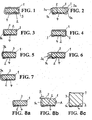
- FIG. 1 one recognizes a foam tape 1 that is shown in the compressed state. It has in the state shown a flat, rectangular cross-section and is provided on its one side, which is to be referred to here and in all the examples explained below as the bottom, with a self-adhesive layer 2, which is shown in dashed lines.
- a film strip 3 is attached by means of the self-adhesive layer 2, which is considerably wider than the foam tape 1.
- the over the width of the foam tape 1 outgoing side strips of the film strip 3 are wrapped around the foam tape 1 and overlap on the top of the Foam Tape 1.
- the film tape 3 is provided with a plurality of apertures or holes.
- the film strip 3 is covered by a cover 4.
- the breakthroughs or holes in the film strip 3 are sufficiently large that adherence of the covering film 4 achieves adhesion thereof through holes in the film strip 3 on the self-adhesive layer 2.
- FIG. 2 shows an embodiment of the invention in which a self-adhesive layer 2 on one side provided foam tape 1 is covered by a film strip 3, one edge between the self-adhesive layer 2 and an adhesive on the self-adhesive layer 2 cover 4 are inserted and is held by the self-adhesive layer 2 and the other edge of which lies on the covering film 4 and is held in the winding (not shown) between the separating film 4 and the foam tape 1 of the adjacent winding (not shown).
- the film strip 3 has in the region of the side edges 1a of the foam tape 1 a Aufgehreserve in the form of loose folds 3a, which can be realized by only a single fold or bulging of the film strip 3. If the foam tape 1 from the in Fig. 2 shown state rises, the film strip 3 on the in Fig. 2 slip right side edge 1a of the foam tape 1 and allows a total of an extremely strong rising of the foam tape 1, without the in Fig. 2 left side edge 1a of the same uncovered
- FIG. 3 shows a third embodiment of the invention, in which a film strip 3 is inserted at one edge of the underside of a foam tape 1 between a located on the underside of the foam tape 1 self-adhesive layer 2 and the edge of this covering cover 4.
- the film strip 3 is led up to a side edge 1a of the foam tape 1 and placed over the top thereof.
- FIG. 4 shows a modification of the embodiment of FIG. 3 , which differs from the latter in that on both sides of the foam tape 1 foil tapes 3 are attached to the self-adhesive layer 2 and covered by the edges of the cover 4. The two film strips 3 are wrapped around the foam tape 1 and overlap each other at the top.
- FIG. 5 shows a second variant of the embodiment of FIG. 3 , This differs from the embodiment according to FIG. 3 in that a longitudinal pocket 3b is formed on the foil strip 3, which can be filled with a material of predetermined quality, for example an intumescent material.
- a material of predetermined quality for example an intumescent material.
- this embodiment agrees with the FIG. 3 match.
- the embodiment according to FIG. 5 also in the sense of FIG. 4 can be modified, namely that two film strips 3 are provided, of which only one or both with a pocket 3b after FIG. 5 can be equipped.
- FIG. 6 shows a third variant of the embodiment from FIG. 3 ,
- the film strip 3 forms on the side edge 1a of the foam tape 1, a series of folds 3a, which allow the foam strip 1 when relaxing reaches a greater height than in the embodiment of FIG. 3 Without the side edge 1a remains uncovered by the film strip 3.
- This embodiment can again in the sense of the embodiment of FIG. 4 be symmetrical.
- the folds 3a can also be arranged on the upper side of the sealing strip like a loop (not shown in the drawing).
- the part of the fold 3a which touches the upper side of the sealing strip, there be selectively fixed or flat (eg glued), wherein the remaining part of the fold 3a forms the Aufgehreserve and is released upon expansion of the foam 1.
- FIG. 7 is a variant of the embodiment of FIG. 6 , It differs from the latter in that the pleats 3a are adhered internally to a retarding adhesive that allows the foam tape 1 to relax to a greater extent, but does so only at a speed determined by said adhesive.
- FIGS. 8a to 8c show the operation of a sealing tape according to the invention, wherein here as an example of the explanation here after that FIG. 3 is used.
- FIG. 8a shows the state of the sealing tape on the roll, but without representing the role. This state, the sealing tape also takes a directly after it has been released from the role, if the foam tape 1 is impregnated with a delaying its recovery impregnation. In the further course, the foam tape 1 then stands in the direction of the arrow A due to the elastic restoring force inherent in the foam material. This has the consequence that the film strip 3 slips over the upper edge, which connects the covered of the film strip 3 side edge 1a with the top of the foam tape 1. This movement is in FIG. 8b marked with the arrow B.
- the film strip 3 is almost completely slipped from the top of the foam tape 1 and still covers the entire side edge 1a of the foam tape 1.
- This condition exists, for example, when a equipped with the sealing tape frame component inserted into a building opening and is sealed by the sealing tape on the soffit of the building opening. It should be emphasized, however, that then the cover 4 is peeled off, since the sealing tape is adhered using the self-adhesive layer 2 to the respective frame component.
Landscapes
- Engineering & Computer Science (AREA)
- General Engineering & Computer Science (AREA)
- Civil Engineering (AREA)
- Structural Engineering (AREA)
- Architecture (AREA)
- Mechanical Engineering (AREA)
- Physics & Mathematics (AREA)
- Electromagnetism (AREA)
- Gasket Seals (AREA)
- Adhesive Tapes (AREA)
- Sealing Material Composition (AREA)
- Laminated Bodies (AREA)
- Decoration Of Textiles (AREA)
- Insulation, Fastening Of Motor, Generator Windings (AREA)
- Lining Or Joining Of Plastics Or The Like (AREA)
Claims (24)
- Rouleau de bande d'étanchéité comprenant une bande de mousse souple (1), formée en un enroulement, de section transversale rectangulaire, qui présente deux flancs latéraux (1a), situés extérieurement sur l'enroulement, un côté supérieur et un côté inférieur, et comprenant au moins un ruban de film (3), qui recouvre au moins l'un des flancs latéraux (1a) de la bande de mousse souple (1) et présente deux bords longitudinaux,
dans lequel,
le rouleau de bande d'étanchéité est en forme de disque, le ruban de film (3) s'enroule comme un escargot de la même façon que la bande de mousse souple (1),
une couche auto-adhésive (2) est disposée sur le côté inférieur de la bande de mousse souple (1), couche sur laquelle est fixée au moins une section du ruban de film (3), et
les deux bords du ruban de film (3) se situent entre des spires mutuellement voisines à l'intérieur de l'enroulement. - Rouleau de bande d'étanchéité suivant la revendication 1, caractérisé en ce qu'une feuille de couverture (4) recouvre le côté inférieur de la bande de mousse souple (1) et la couche auto-adhésive (2).
- Rouleau de bande d'étanchéité suivant l'une des revendications 1 et 2, caractérisé en ce que le ruban de film (3) recouvre totalement la couche auto-adhésive (2) de la bande de mousse souple (1), est guidé bilatéralement hors de l'enroulement sur la spire, sur laquelle il est collé en partie basse, est rabattu bilatéralement sur le côté supérieur de la bande de mousse souple (1) et inséré par ses deux bords entre cette spire et la spire voisine.
- Rouleau de bande d'étanchéité suivant la revendication 3, caractérisé en ce que le ruban de film (3) est muni d'une multiplicité de percées dans sa section adhérant à la couche auto-adhésive (2) et est recouvert d'une feuille de couverture (4) sur son côté opposé à la couche auto-adhésive (2).
- Rouleau de bande d'étanchéité suivant la revendication 1, caractérisé en ce que la bande de mousse souple (1) est équipée unilatéralement d'une couche adhésive et est munie d'une feuille de couverture (4), que le ruban de film (3) présente une largeur, qui correspond au moins à la largeur de la bande de mousse souple (1) en plus de la hauteur de cette dernière dans l'état de compression, et que la section du ruban de film (3) est insérée au-dessous de la feuille de couverture (4) sur au moins un côté de la bande de mousse souple (1) dans la zone de bordure de cette dernière.
- Rouleau de bande d'étanchéité suivant la revendication 5, caractérisé en ce que la zone du ruban de film (3), non adhérente à la couche auto-adhésive (2), recouvre un flanc latéral (1a) et le côté supérieur de la bande de mousse souple (1).
- Rouleau de bande d'étanchéité suivant la revendication 6, caractérisé en ce que la zone du ruban de film (3), non adhérente à la couche auto-adhésive (2), recouvre également le second flanc latéral (1a) de la bande de mousse souple (1).
- Rouleau de bande d'étanchéité suivant la revendication 7, caractérisé en ce que le second bord du ruban de film (3) est inséré entre le côté de la feuille de couverture (4), opposé à la couche auto-adhésive (2), et le côté supérieur de la bande de mousse souple (1) de la spire voisine.
- Rouleau de bande d'étanchéité suivant l'une des revendications précédentes, caractérisé en ce que le ruban de film (3a) est muni de plusieurs plis longitudinaux (3a) dans sa section s'appliquant sur le flanc latéral (1a) de la bande de mousse souple (1).
- Rouleau de bande d'étanchéité suivant l'une des revendications précédentes, caractérisé en ce que le ruban de film (3) présente sur le côté supérieur de la bande de mousse souple (1) un pli configuré en une boucle, qui forme une réserve de gonflement.
- Rouleau de bande d'étanchéité suivant la revendication 9, caractérisé en ce que les plis (3a) sont collés chacun en soi avec un adhésif se décollant à retardement, qui retarde le gonflement de la bande de mousse souple (1) comprimée.
- Rouleau de bande d'étanchéité suivant l'une des revendications 1 à 8, caractérisé en ce que le ruban de film (3) est muni d'une poche longitudinale (3b) dans sa zone s'appliquant sur le flanc latéral (1a) de la bande de mousse souple (1).
- Rouleau de bande d'étanchéité suivant la revendication 12, caractérisé en ce que la poche (3b) est remplie d'une matière intumescente.
- Rouleau de bande d'étanchéité suivant l'une des revendications précédentes, caractérisé en ce que la bande de mousse souple (1) est comprimée avec une possibilité de rappel élastique à l'intérieur du rouleau.
- Procédé de fabrication d'un rouleau de bande d'étanchéité suivant la revendication 1, comprenant les étapes suivantes :application d'une couche auto-adhésive (2) et d'une feuille de couverture (4) sur un côté inférieur d'une large bande de mousse souple (1),enroulement de la bande de mousse souple et blocage de la bande de rouleaux en mousse souple ainsi formée,découpe de la bande de rouleaux en mousse souple en rouleaux de bande d'étanchéité en forme de disques d'une largeur prédéfinie,décollement mécanique progressif de l'assemblage entre la couche auto-adhésive (2) et la feuille de couverture (4) de chaque rouleau de bande d'étanchéité sur au moins une partie de la largeur de ce dernier,insertion d'un ruban de film (3) flexible et lâche dans la fente ainsi produite, le ruban de film (3) présentant alors une largeur qui correspond au moins à la somme de la largeur de la section du ruban de film (3), insérée dans la fente, et de l'épaisseur d'une couche de mousse souple dans l'état de compression et au moins à une partie de la largeur du rouleau de bande d'étanchéité,fixation du ruban de film (3) sur la couche auto-adhésive (2) et fermeture de la fente etrabattement continu de la zone du ruban de film (3),dépassant du rouleau de bande d'étanchéité, sur ce dernier et insertion du ruban de film (3) entre le côté supérieur de la couche de mousse souple, avec laquelle est collé le ruban de film (3), et la feuille de couverture (4) adhérant sur la couche de mousse souple voisine.
- Procédé suivant la revendication 15, caractérisé en ce que la fixation du ruban de film (3) sur la couche auto-adhésive (2) et le traitement ultérieur du ruban de film (3) fixé, dépassant de la bande d'étanchéité, sont réalisés en une opération unique.
- Procédé de fabrication d'un rouleau de bande d'étanchéité suivant la revendication 1, comprenant les étapes suivantes :application d'une couche auto-adhésive (2) et d'une feuille de couverture (4) sur un côté inférieur d'une bande large de mousse souple (1),enroulement de la bande de mousse souple et blocage de la bande de rouleaux en mousse souple ainsi formée,découpe de la bande de rouleaux en mousse souple en rouleaux de bande d'étanchéité en forme de disques d'une largeur prédéfinie,déroulement d'un rouleau de bande d'étanchéité en forme de disque,décollement mécanique progressif de l'assemblage entre la couche auto-adhésive (2) et la feuille de couverture (4) de chaque bande d'étanchéité déroulée sur au moins une partie de la largeur de cette dernière,insertion d'un ruban de film (3) flexible et lâche dans la fente ainsi produite, le ruban de film (3) présentant alors une largeur, qui correspond au moins à la somme de la largeur de la section du ruban de film (3), insérée dans la fente, et de l'épaisseur d'une couche de mousse souple dans l'état de compression et au moins à une partie de la largeur de la bande d'étanchéité,fixation du ruban de film (3) sur la couche auto-adhésive (2) sur au moins une partie de la largeur de cette dernière et fermeture de la fente,rabattement continu de la zone du ruban de film (3),dépassant du rouleau de bande d'étanchéité, sur la bande d'étanchéité, etenroulement de la bande d'étanchéité comprimée en un rouleau de bande d'étanchéité.
- Procédé suivant l'une des revendications 15 à 17, caractérisé en ce que l'assemblage collé entre la couche auto-adhésive (2) et la feuille de couverture (4) n'est décollé mécaniquement de façon progressive que sur un côté de la bande d'étanchéité et que sur une partie de la largeur de cette dernière et seule une section de bordure du ruban de film (3) est insérée dans la fente ainsi produite.
- Procédé suivant l'une des revendications 15 à 17, caractérisé en ce que l'assemblage collé entre la couche auto-adhésive (2) et la feuille de couverture (4) est d'abord décollé mécaniquement de façon progressive sur un premier côté de la bande d'étanchéité et seulement sur une partie de la largeur de cette dernière, une première section de bordure d'un ruban de film (3) est insérée et fixée dans la fente ainsi produite, le ruban de film (3) ayant alors une largeur, égale à la somme du double de la largeur du ruban inséré, du double de l'épaisseur de la bande de mousse souple (1) dans l'état de compression et de la largeur de la bande de mousse souple (1), que le ruban de film (3) est enlacé autour de la spire de la bande de mousse souple (1), sur laquelle il est fixé, que l'assemblage collé entre la couche auto-adhésive (2) et la feuille de couverture (4) est décollé mécaniquement de façon progressive sur l'autre côté de la bande d'étanchéité et seulement sur une partie de la largeur de cette dernière et la seconde section de bordure du ruban de film (3) est insérée et fixée dans la fente ainsi produite.
- Procédé suivant l'une des revendications 15 à 19, caractérisé en ce que, lors de la fixation de la section de bordure du ruban de film (3), environ 2 mm de sa largeur sont insérés dans la fente et fixés sur la surface adhésive.
- Dispositif de fabrication d'un rouleau de bande d'étanchéité suivant la revendication 1 par équipement d'un rouleau de bande d'étanchéité en un ruban de film (3), lequel rouleau comprend une bande de mousse souple (1) de section transversale rectangulaire, qui est munie sur son côté inférieur d'une couche auto-adhésive (2) recouverte d'une feuille de couverture (4) et est enroulée dans l'état de compression en un rouleau de bande d'étanchéité, sur un corps d'enroulement rond, de telle sorte que la bande de mousse souple (1) et la feuille de couverture (4) alternent dans la direction radiale, dispositif comprenant :un plateau tournant pour la pose d'un rouleau de bande d'étanchéité,un dispositif de maintien du rouleau de bande d'étanchéité sur le plateau tournant dans une position centrée sur l'axe de rotation de ce dernier,au moins un sabot en forme de charrue, fixé par l'intermédiaire du plateau tournant sur un support,lequel sabot présente une arête de sortie et un côté arrière,un dispositif de déplacement du support dans la direction radiale par rapport au plateau tournant,un dispositif d'arrivée d'un ruban de film (3) en direction du sabot à partir du côté arrière de ce dernier,un dispositif d'abaissement du support en direction du plateau tournant etun dispositif de rotation du plateau tournant dans la direction orientée du côté arrière en direction de l'arête de sortie du sabot.
- Dispositif suivant la revendication 21, dans lequel deux sabots en forme de charrue sont disposés sur le support à distance mutuelle radiale et avec un écartement angulaire.
- Dispositif de fabrication d'un rouleau de bande d'étanchéité suivant la revendication 1 par équipement d'un rouleau de bande d'étanchéité en un ruban de film (3), lequel rouleau comprend une bande de mousse souple (1) de section transversale rectangulaire, qui est munie sur un côté inférieur d'une couche auto-adhésive (2) recouverte d'une feuille de couverture (4) et est enroulée dans l'état de compression, pour former le rouleau de bande d'étanchéité, sur un corps d'enroulement rond de telle sorte que la bande de mousse souple (1) et la feuille de couverture (4) alternent dans la direction radiale, dispositif comprenant :deux bancs d'enroulement, dont un banc de déroulement se prête à recevoir un rouleau de bande d'étanchéité à traiter, et un banc d'enroulement se prête à recevoir un corps d'enroulement, sur lequel doit être enroulé le rouleau de bande d'étanchéité conforme à l'invention,avec des dispositifs correspondants pour le freinage du premier banc d'enroulement et pour l'entraînement du deuxième banc d'enroulement,un dispositif disposé entre les deux bancs d'enroulement avec un sabot, qui est conçu pour être introduit entre la feuille de couverture (4) et la couche auto-adhésive (2) de la bande d'étanchéité déroulée, s'étendant entre les deux bancs d'enroulement,un troisième banc d'enroulement, qui est prévu pour recevoir une bobine pour un ruban de film (3),des dispositifs de guidage entre le troisième banc d'enroulement et le sabot, qui sont conçus pour guider un ruban de film (3) du troisième banc d'enroulement en direction du sabot, etdes dispositifs de rabattement, disposés entre le sabot et le deuxième banc d'enroulement, pour rabattre le ruban de film (3) sur le côté supérieur libre de la bande de mousse souple (1).
- Dispositif suivant la revendication 23, caractérisé en ce que des dispositifs se situent dans l'espace intermédiaire compris entre le premier et le deuxième banc d'enroulement, lesquels dispositifs se prêtent à maintenir largement dans l'état de compression la bande d'étanchéité déroulée du premier banc d'enroulement, état dans lequel elle sort du premier banc d'enroulement.
Priority Applications (17)
| Application Number | Priority Date | Filing Date | Title |
|---|---|---|---|
| AT06026192T ATE431912T1 (de) | 2006-12-18 | 2006-12-18 | Dichtband aus weichschaum und verfahren zu seiner herstellung |
| EP20060026192 EP1936246B2 (fr) | 2006-12-18 | 2006-12-18 | Bande en mousse et sa méthode de fabrication |
| DE200620020097 DE202006020097U1 (de) | 2006-12-18 | 2006-12-18 | Dichtbandrolle aus Weichschaumstoff |
| DE200650003781 DE502006003781D1 (de) | 2006-12-18 | 2006-12-18 | Dichtband aus Weichschaum und Verfahren zu seiner Herstellung |
| DK06026192T DK1936246T4 (da) | 2006-12-18 | 2006-12-18 | Tætningsbånd af skummateriale og fremgangsmåde til fremstilling deraf |
| PL06026192T PL1936246T5 (pl) | 2006-12-18 | 2006-12-18 | Taśma uszczelniająca z miękkiego tworzywa piankowego i sposób jej wytwarzania |
| DK07019056T DK1936247T3 (da) | 2006-12-18 | 2007-09-27 | Tætningsbånd af blödt skum |
| DE200750001239 DE502007001239D1 (de) | 2006-12-18 | 2007-09-27 | Dichtband aus weichem Schaumstoff |
| PL07019056T PL1936247T3 (pl) | 2006-12-18 | 2007-09-27 | Taśma uszczelniająca z miękkiego tworzywa piankowego |
| AT07019056T ATE438819T1 (de) | 2006-12-18 | 2007-09-27 | Dichtband aus weichem schaumstoff |
| EP20070019056 EP1936247B1 (fr) | 2006-12-18 | 2007-09-27 | Bande d'étanchéité en mousse |
| PCT/EP2007/010433 WO2008074390A1 (fr) | 2006-12-18 | 2007-11-30 | Ruban d'étanchéité en mousse souple et procédé de production de ce ruban d'étanchéité |
| PCT/EP2007/010432 WO2008074389A1 (fr) | 2006-12-18 | 2007-11-30 | Ruban d'étanchéité en mousse souple |
| US12/448,381 US8318280B2 (en) | 2006-12-18 | 2007-11-30 | Sealing tape of soft foam and method for its production |
| US12/448,382 US8349426B2 (en) | 2006-12-18 | 2007-11-30 | Sealing tape of soft foam |
| NO20092531A NO339993B1 (no) | 2006-12-18 | 2009-07-03 | Tettebånd med mykt skumstoff |
| NO20092532A NO343822B1 (no) | 2006-12-18 | 2009-07-03 | Tettebånd av mykskum og fremgangsmåte for dets tilvirkning |
Applications Claiming Priority (1)
| Application Number | Priority Date | Filing Date | Title |
|---|---|---|---|
| EP20060026192 EP1936246B2 (fr) | 2006-12-18 | 2006-12-18 | Bande en mousse et sa méthode de fabrication |
Publications (3)
| Publication Number | Publication Date |
|---|---|
| EP1936246A1 EP1936246A1 (fr) | 2008-06-25 |
| EP1936246B1 EP1936246B1 (fr) | 2009-05-20 |
| EP1936246B2 true EP1936246B2 (fr) | 2013-04-03 |
Family
ID=38016916
Family Applications (1)
| Application Number | Title | Priority Date | Filing Date |
|---|---|---|---|
| EP20060026192 Active EP1936246B2 (fr) | 2006-12-18 | 2006-12-18 | Bande en mousse et sa méthode de fabrication |
Country Status (8)
| Country | Link |
|---|---|
| US (1) | US8318280B2 (fr) |
| EP (1) | EP1936246B2 (fr) |
| AT (2) | ATE431912T1 (fr) |
| DE (2) | DE502006003781D1 (fr) |
| DK (2) | DK1936246T4 (fr) |
| NO (1) | NO343822B1 (fr) |
| PL (1) | PL1936246T5 (fr) |
| WO (1) | WO2008074390A1 (fr) |
Families Citing this family (30)
| Publication number | Priority date | Publication date | Assignee | Title |
|---|---|---|---|---|
| EP2138664B1 (fr) * | 2008-06-23 | 2015-04-15 | ISO-Chemie GmbH | Bande d'étanchéité précomprimée |
| DE202009002918U1 (de) | 2009-03-02 | 2010-07-22 | Lehrhuber, Konrad | Dichtvorrichtung zur Fugenabdichtung zwischen zwei Bauteilen |
| WO2011057234A1 (fr) | 2009-11-09 | 2011-05-12 | Federal-Mogul Powertrain, Inc. | Entretoise à éléments allongés pouvant être enroulée et à profil bas et procédé destiné à maintenir les éléments allongés dans une relation relative fixe et espacée |
| DK2415942T3 (da) | 2010-08-05 | 2013-05-27 | Iso Chemie Gmbh | Tætningsbånd |
| DE202011104063U1 (de) | 2011-08-04 | 2014-12-09 | Tremco Illbruck Produktion Gmbh | Fugendichtband sowie Bauwerk mit derartigem Dichtband |
| DE202012005049U1 (de) | 2012-05-23 | 2013-08-26 | Tremco Illbruck Produktion Gmbh | Dichtband |
| DE202012104454U1 (de) | 2012-11-19 | 2014-02-25 | Tremco Illbruck Produktion Gmbh | Zwangsbelüftetes Gebäude mit Wandaufbau umfassend Dichtungsband |
| US10150251B2 (en) | 2013-02-22 | 2018-12-11 | Aeroflex Usa | Connecting systems for adjacent ends of insulation tubing |
| EP2990553B1 (fr) | 2014-08-26 | 2020-01-22 | ISO-Chemie GmbH | Procédé de fabrication d'un rouleau de ruban étanche |
| PL2990576T3 (pl) | 2014-08-26 | 2020-04-30 | Iso-Chemie Gmbh | Taśma uszczelniająca do uszczelniania szczeliny |
| PL2990575T3 (pl) | 2014-08-26 | 2020-05-18 | Iso-Chemie Gmbh | Taśma uszczelniająca do uszczelniania szczeliny |
| EP2990552B1 (fr) | 2014-08-26 | 2018-03-21 | ISO-Chemie GmbH | Procédé de fabrication d'un rouleau de bande d'étanchéité et rouleau de bande d'étanchéité |
| EP2990551B1 (fr) * | 2014-08-26 | 2019-05-08 | ISO-Chemie GmbH | Procédé de fabrication d'un rouleau de ruban étanche |
| EP3056626A1 (fr) * | 2015-02-13 | 2016-08-17 | HILTI Aktiengesellschaft | Bande d'étanchéité de joint ayant une géométrie prédéfinie et système d'étanchéité doté d'une telle bande d'étanchéité de joint |
| JP6472533B2 (ja) | 2015-02-23 | 2019-02-20 | テーザ・ソシエタス・ヨーロピア | ブリッジテープ及び自動車ボディのシートメタル又はプラスチックパーツ中の孔を封止する方法 |
| DE102015116667A1 (de) | 2015-10-01 | 2017-04-06 | Tremco Illbruck Produktion Gmbh | Verfahren zum Herstellen eines Abdichtbands und Abdichtband |
| DE102016111284A1 (de) * | 2016-06-20 | 2017-12-21 | Tremco Illbruck Produktion Gmbh | Dichtband |
| US10480656B2 (en) * | 2016-08-22 | 2019-11-19 | Tesa Se | Bridge tape with directed foam expansion and method for sealing holes in sheet metal or plastic parts of automobile bodies |
| DE102017105033A1 (de) * | 2017-03-09 | 2018-09-13 | Tremco Illbruck Produktion Gmbh | Mit Liner aufgewickeltes Dichtband |
| DE102017110856A1 (de) | 2017-05-18 | 2018-12-06 | tremco illbruck GmbH | Herstellungsverfahren für Dichtband und Dichtband |
| DK3450642T3 (da) | 2017-09-01 | 2020-03-02 | Iso Chemie Gmbh | Fremgangsmåde til fremstilling af en tætningsbåndrulle |
| US20190085547A1 (en) * | 2017-09-18 | 2019-03-21 | Jose Guadalupe Valedez Magana | Self-Adhering Toilet Base Seal with Moisture Indicator |
| EP3567176B1 (fr) | 2018-05-07 | 2020-04-15 | ISO-Chemie GmbH | Procédé de fabrication de rouleaux de bandes d'étanchéité |
| DE102018118854A1 (de) | 2018-08-02 | 2020-02-06 | tremco illbruck GmbH | Herstellungsverfahren für Dichtband und Dichtband |
| DE102019100686B4 (de) * | 2019-01-11 | 2022-03-10 | Tremco CPG Germany GmbH | Verfahren und Vorrichtung zur Herstellung eines Dichtbandes |
| PL3825483T3 (pl) | 2019-11-22 | 2024-06-17 | Iso-Chemie Gmbh | Taśma uszczelniająca |
| EP3825484A1 (fr) | 2019-11-22 | 2021-05-26 | ISO-Chemie GmbH | Bande d'étanchéité |
| EP3825482B1 (fr) | 2019-11-22 | 2025-04-09 | ISO-Chemie GmbH | Bande d'étanchéité |
| EP3825501B1 (fr) * | 2019-11-22 | 2023-06-07 | ISO-Chemie GmbH | Bande d'étanchéité |
| PL3851625T3 (pl) | 2020-01-20 | 2023-10-30 | Iso-Chemie Gmbh | Rolka taśmy uszczelniającej i sposób jej wytwarzania |
Citations (2)
| Publication number | Priority date | Publication date | Assignee | Title |
|---|---|---|---|---|
| EP0219296A1 (fr) † | 1985-10-07 | 1987-04-22 | C.I. Kasei Co., Ltd | Joint |
| WO2001055279A1 (fr) † | 2000-01-25 | 2001-08-02 | Kunimine Industries Co., Ltd. | Matiere d'etancheite resistante a l'eau |
Family Cites Families (15)
| Publication number | Priority date | Publication date | Assignee | Title |
|---|---|---|---|---|
| US3713263A (en) * | 1971-05-07 | 1973-01-30 | W Mullen | Expansion joints for roofs |
| DE2457322A1 (de) | 1974-12-04 | 1976-06-10 | Guenther Kruepper | Verfahren zum ueberziehen von kunststoffkoerpern mit einer lederartigen kunststoffschicht |
| US4181711A (en) * | 1976-07-30 | 1980-01-01 | Nitto Electric Industrial Co., Ltd. | Sealing material |
| US4204373A (en) * | 1978-09-08 | 1980-05-27 | Davidson James D | Compressed expandable insulation tape and method |
| US4344265A (en) * | 1980-07-14 | 1982-08-17 | Davidson James D | Energy conserving building structural elements normally called window or door frames |
| DE3133271A1 (de) * | 1981-08-22 | 1983-03-03 | Irbit Holding AG, 1701 Fribourg | Zu einer rolle aufgewickelter schaumstoff-streifen, vorzugsweise zu abdichtungszwecken |
| US4356676A (en) * | 1981-09-21 | 1982-11-02 | Norton Company | Sealant strip |
| DE4123647B4 (de) | 1991-06-01 | 2004-03-18 | Irbit Research + Consulting Ag | Dichtband |
| DE4307528A1 (de) * | 1993-03-10 | 1994-09-15 | Illbruck Gmbh | Fugendichtungsband |
| DE19641415C5 (de) | 1996-10-08 | 2017-02-09 | Hanno-Werk Gmbh & Co. Kg | Dichtungsband und Verfahren zur Herstellung des Dichtungsbandes und seine Verwendung |
| SE9701292D0 (sv) * | 1997-04-09 | 1997-04-09 | Johan Stroemberg | Tätningsremsa mellan två konstruktionsdelar |
| DE29715660U1 (de) | 1997-09-01 | 1999-05-27 | Illbruck Bau-Technik GmbH & Co. KG, 51381 Leverkusen | Bandartiges Verbindungselement |
| DE19944611A1 (de) * | 1999-09-17 | 2001-03-22 | Illbruck Gmbh | Dichtstreifen zur Abdichtung einer Fuge |
| US8097310B2 (en) * | 2003-02-07 | 2012-01-17 | 3M Innovative Properties Company | Firestop article with attachment surface |
| DE102004012473A1 (de) | 2004-03-15 | 2005-10-06 | Illbruck Building Systems Gmbh | Bandartiges Verbindungselement |
-
2006
- 2006-12-18 DK DK06026192T patent/DK1936246T4/da active
- 2006-12-18 AT AT06026192T patent/ATE431912T1/de active
- 2006-12-18 PL PL06026192T patent/PL1936246T5/pl unknown
- 2006-12-18 EP EP20060026192 patent/EP1936246B2/fr active Active
- 2006-12-18 DE DE200650003781 patent/DE502006003781D1/de active Active
-
2007
- 2007-09-27 DE DE200750001239 patent/DE502007001239D1/de active Active
- 2007-09-27 DK DK07019056T patent/DK1936247T3/da active
- 2007-09-27 AT AT07019056T patent/ATE438819T1/de active
- 2007-11-30 WO PCT/EP2007/010433 patent/WO2008074390A1/fr not_active Ceased
- 2007-11-30 US US12/448,381 patent/US8318280B2/en active Active
-
2009
- 2009-07-03 NO NO20092532A patent/NO343822B1/no unknown
Patent Citations (2)
| Publication number | Priority date | Publication date | Assignee | Title |
|---|---|---|---|---|
| EP0219296A1 (fr) † | 1985-10-07 | 1987-04-22 | C.I. Kasei Co., Ltd | Joint |
| WO2001055279A1 (fr) † | 2000-01-25 | 2001-08-02 | Kunimine Industries Co., Ltd. | Matiere d'etancheite resistante a l'eau |
Non-Patent Citations (18)
| Title |
|---|
| "Auszug des Besprechungsprotokol", 13 October 2005 (2005-10-13) † |
| "Brockhaus Enzyklopädie", vol. 19 † |
| "Flyer Messe Bau", January 2005 (2005-01-01) † |
| "Flyer Messe Fensterbau", March 2004 (2004-03-01) † |
| "Formblatt Erfassung Externe Reklamationen", 4 October 2005 (2005-10-04) † |
| "Lueger Techniklexikon", April 1972 † |
| "Lueger Techniklexikon", August 1972 † |
| "Meyers ENZYKLOPÄDISCHES LEXIKON", LEXIKONVERLAG † |
| "Meyers Lexikon der Technik", ALLGEMEINER VERLAG † |
| "Planungsordner Abdichtungsssysteme", February 2004 (2004-02-01) † |
| "Preisliste illbruck", June 2001 (2001-06-01) † |
| "Rechnung", 22 November 2006 (2006-11-22) † |
| KWD FENSTER, November 2004 (2004-11-01) † |
| PROSPEKT TREMCO ILLBRUCK, vol. 03, 2002 † |
| PROSPEKT TREMCO ILLBRUCK, vol. 03, 2004 † |
| PROSPEKT TREMCO ILLBRUCK, vol. 04, 2005 † |
| PROSPEKT TREMCO ILLBRUCK, vol. 07, 2005 † |
| PROSPEKT TREMCO ILLBRUCK, vol. 08, 2003 † |
Also Published As
| Publication number | Publication date |
|---|---|
| EP1936246B1 (fr) | 2009-05-20 |
| ATE431912T1 (de) | 2009-06-15 |
| NO20092532L (no) | 2009-09-09 |
| DK1936246T3 (da) | 2009-08-24 |
| EP1936246A1 (fr) | 2008-06-25 |
| ATE438819T1 (de) | 2009-08-15 |
| DE502007001239D1 (de) | 2009-09-17 |
| WO2008074390A1 (fr) | 2008-06-26 |
| NO343822B1 (no) | 2019-06-11 |
| US20100009118A1 (en) | 2010-01-14 |
| DE502006003781D1 (de) | 2009-07-02 |
| DK1936247T3 (da) | 2009-12-07 |
| PL1936246T3 (pl) | 2009-10-30 |
| US8318280B2 (en) | 2012-11-27 |
| DK1936246T4 (da) | 2013-06-24 |
| PL1936246T5 (pl) | 2013-07-31 |
Similar Documents
| Publication | Publication Date | Title |
|---|---|---|
| EP1936246B2 (fr) | Bande en mousse et sa méthode de fabrication | |
| EP1936247B1 (fr) | Bande d'étanchéité en mousse | |
| EP2107176B1 (fr) | Production d'une bande d'étanchéité en mousse souple | |
| EP2415942B1 (fr) | Bande étanche | |
| EP2666947B1 (fr) | Bande étanche | |
| EP2333177A1 (fr) | Bande d'étanchéité pré-comprimée | |
| DE4033850A1 (de) | Zu einer rolle endlos aufgewickeltes, zusammengesetztes laminatklebeband und verfahren zur herstellung der rolle des laminatklebebandes | |
| EP2065548A2 (fr) | Bande étanche alvéolaire | |
| EP2138664A1 (fr) | Bande d'étanchéité précomprimée | |
| DE102015108702A1 (de) | Halb vorgeschnittenes, doppelseitiges Bandprodukt und Verfahren zum Herstellen desselben | |
| EP3513954A1 (fr) | Bande d'étanchéité et procédé de fabrication d'une bande d'étanchéité | |
| DE102008003337A1 (de) | Handgerät zum Abrollen von einem Klebeband mit einem doppelseitig klebend ausgerüsteten Träger, wobei zumindest eine der beiden klebenden Seiten des Trägers mit einem Trennmaterial eingedeckt ist | |
| EP2990552A1 (fr) | Procédé de fabrication d'un rouleau de bande d'étanchéité et rouleau de bande d'étanchéité | |
| DE69405445T2 (de) | Verfahren und Vorrichtung zum Verkleben eines Kantenschutzklebebandes auf dem Rand einer mehrschichtigen Verbundplatte, wie eine Wärmeschutzplatte eines Raumfahrzeuges | |
| EP0513720B1 (fr) | Bande de couverture et d'étanchéité | |
| EP3567177B1 (fr) | Procédé de fabrication de rouleaux de bandes d'étanchéité | |
| DE102017110856A1 (de) | Herstellungsverfahren für Dichtband und Dichtband | |
| DE60209524T2 (de) | Eingekapseltes isolierungsprodukt und dessen herstellungsverfahren | |
| DE102019100686B4 (de) | Verfahren und Vorrichtung zur Herstellung eines Dichtbandes | |
| EP2164436B1 (fr) | Portions de stratifie stable | |
| WO2021073906A1 (fr) | Bande d'étanchéité pour étanchéifier des joints de structure | |
| DE102008001456A1 (de) | Verfahren zum Überführen einer laufenden Materialbahn sowie Wickelmaschine zur Durchführung des Verfahrens | |
| DE202006020097U1 (de) | Dichtbandrolle aus Weichschaumstoff | |
| DE102021101899A1 (de) | Dichtband zum Abdichten von Bauwerksfugen | |
| EP2409855A1 (fr) | Procédé et section de feuilles de support pour l'application simplifiée de films adhésifs décoratifs sur des stores |
Legal Events
| Date | Code | Title | Description |
|---|---|---|---|
| PUAI | Public reference made under article 153(3) epc to a published international application that has entered the european phase |
Free format text: ORIGINAL CODE: 0009012 |
|
| 17P | Request for examination filed |
Effective date: 20070827 |
|
| AK | Designated contracting states |
Kind code of ref document: A1 Designated state(s): AT BE BG CH CY CZ DE DK EE ES FI FR GB GR HU IE IS IT LI LT LU LV MC NL PL PT RO SE SI SK TR |
|
| AX | Request for extension of the european patent |
Extension state: AL BA HR MK RS |
|
| GRAP | Despatch of communication of intention to grant a patent |
Free format text: ORIGINAL CODE: EPIDOSNIGR1 |
|
| AKX | Designation fees paid |
Designated state(s): AT BE BG CH CY CZ DE DK EE ES FI FR GB GR HU IE IS IT LI LT LU LV MC NL PL PT RO SE SI SK TR |
|
| GRAS | Grant fee paid |
Free format text: ORIGINAL CODE: EPIDOSNIGR3 |
|
| GRAA | (expected) grant |
Free format text: ORIGINAL CODE: 0009210 |
|
| AK | Designated contracting states |
Kind code of ref document: B1 Designated state(s): AT BE BG CH CY CZ DE DK EE ES FI FR GB GR HU IE IS IT LI LT LU LV MC NL PL PT RO SE SI SK TR |
|
| REG | Reference to a national code |
Ref country code: GB Ref legal event code: FG4D Free format text: NOT ENGLISH |
|
| REG | Reference to a national code |
Ref country code: CH Ref legal event code: EP |
|
| REG | Reference to a national code |
Ref country code: RO Ref legal event code: EPE |
|
| REG | Reference to a national code |
Ref country code: IE Ref legal event code: FG4D Free format text: LANGUAGE OF EP DOCUMENT: GERMAN |
|
| REF | Corresponds to: |
Ref document number: 502006003781 Country of ref document: DE Date of ref document: 20090702 Kind code of ref document: P |
|
| REG | Reference to a national code |
Ref country code: DK Ref legal event code: T3 |
|
| REG | Reference to a national code |
Ref country code: SE Ref legal event code: TRGR |
|
| PG25 | Lapsed in a contracting state [announced via postgrant information from national office to epo] |
Ref country code: ES Free format text: LAPSE BECAUSE OF FAILURE TO SUBMIT A TRANSLATION OF THE DESCRIPTION OR TO PAY THE FEE WITHIN THE PRESCRIBED TIME-LIMIT Effective date: 20090831 Ref country code: LT Free format text: LAPSE BECAUSE OF FAILURE TO SUBMIT A TRANSLATION OF THE DESCRIPTION OR TO PAY THE FEE WITHIN THE PRESCRIBED TIME-LIMIT Effective date: 20090520 Ref country code: PT Free format text: LAPSE BECAUSE OF FAILURE TO SUBMIT A TRANSLATION OF THE DESCRIPTION OR TO PAY THE FEE WITHIN THE PRESCRIBED TIME-LIMIT Effective date: 20090920 |
|
| REG | Reference to a national code |
Ref country code: PL Ref legal event code: T3 |
|
| PG25 | Lapsed in a contracting state [announced via postgrant information from national office to epo] |
Ref country code: IS Free format text: LAPSE BECAUSE OF FAILURE TO SUBMIT A TRANSLATION OF THE DESCRIPTION OR TO PAY THE FEE WITHIN THE PRESCRIBED TIME-LIMIT Effective date: 20090920 Ref country code: SI Free format text: LAPSE BECAUSE OF FAILURE TO SUBMIT A TRANSLATION OF THE DESCRIPTION OR TO PAY THE FEE WITHIN THE PRESCRIBED TIME-LIMIT Effective date: 20090520 Ref country code: LV Free format text: LAPSE BECAUSE OF FAILURE TO SUBMIT A TRANSLATION OF THE DESCRIPTION OR TO PAY THE FEE WITHIN THE PRESCRIBED TIME-LIMIT Effective date: 20090520 |
|
| REG | Reference to a national code |
Ref country code: HU Ref legal event code: AG4A Ref document number: E006390 Country of ref document: HU |
|
| PG25 | Lapsed in a contracting state [announced via postgrant information from national office to epo] |
Ref country code: EE Free format text: LAPSE BECAUSE OF FAILURE TO SUBMIT A TRANSLATION OF THE DESCRIPTION OR TO PAY THE FEE WITHIN THE PRESCRIBED TIME-LIMIT Effective date: 20090520 |
|
| PLBI | Opposition filed |
Free format text: ORIGINAL CODE: 0009260 |
|
| 26 | Opposition filed |
Opponent name: TREMCO ILLBRUCK PRODUKTION GMBH Effective date: 20100218 |
|
| PLAX | Notice of opposition and request to file observation + time limit sent |
Free format text: ORIGINAL CODE: EPIDOSNOBS2 |
|
| PG25 | Lapsed in a contracting state [announced via postgrant information from national office to epo] |
Ref country code: BG Free format text: LAPSE BECAUSE OF FAILURE TO SUBMIT A TRANSLATION OF THE DESCRIPTION OR TO PAY THE FEE WITHIN THE PRESCRIBED TIME-LIMIT Effective date: 20090820 |
|
| PLBB | Reply of patent proprietor to notice(s) of opposition received |
Free format text: ORIGINAL CODE: EPIDOSNOBS3 |
|
| PG25 | Lapsed in a contracting state [announced via postgrant information from national office to epo] |
Ref country code: MC Free format text: LAPSE BECAUSE OF NON-PAYMENT OF DUE FEES Effective date: 20100701 |
|
| PG25 | Lapsed in a contracting state [announced via postgrant information from national office to epo] |
Ref country code: LU Free format text: LAPSE BECAUSE OF NON-PAYMENT OF DUE FEES Effective date: 20091218 |
|
| PG25 | Lapsed in a contracting state [announced via postgrant information from national office to epo] |
Ref country code: TR Free format text: LAPSE BECAUSE OF FAILURE TO SUBMIT A TRANSLATION OF THE DESCRIPTION OR TO PAY THE FEE WITHIN THE PRESCRIBED TIME-LIMIT Effective date: 20090520 |
|
| PG25 | Lapsed in a contracting state [announced via postgrant information from national office to epo] |
Ref country code: CY Free format text: LAPSE BECAUSE OF FAILURE TO SUBMIT A TRANSLATION OF THE DESCRIPTION OR TO PAY THE FEE WITHIN THE PRESCRIBED TIME-LIMIT Effective date: 20090520 |
|
| PLAB | Opposition data, opponent's data or that of the opponent's representative modified |
Free format text: ORIGINAL CODE: 0009299OPPO |
|
| R26 | Opposition filed (corrected) |
Opponent name: TREMCO ILLBRUCK PRODUKTION GMBH Effective date: 20100218 |
|
| APAH | Appeal reference modified |
Free format text: ORIGINAL CODE: EPIDOSCREFNO |
|
| APBM | Appeal reference recorded |
Free format text: ORIGINAL CODE: EPIDOSNREFNO |
|
| APBP | Date of receipt of notice of appeal recorded |
Free format text: ORIGINAL CODE: EPIDOSNNOA2O |
|
| APBU | Appeal procedure closed |
Free format text: ORIGINAL CODE: EPIDOSNNOA9O |
|
| PUAH | Patent maintained in amended form |
Free format text: ORIGINAL CODE: 0009272 |
|
| STAA | Information on the status of an ep patent application or granted ep patent |
Free format text: STATUS: PATENT MAINTAINED AS AMENDED |
|
| 27A | Patent maintained in amended form |
Effective date: 20130403 |
|
| AK | Designated contracting states |
Kind code of ref document: B2 Designated state(s): AT BE BG CH CY CZ DE DK EE ES FI FR GB GR HU IE IS IT LI LT LU LV MC NL PL PT RO SE SI SK TR |
|
| REG | Reference to a national code |
Ref country code: CH Ref legal event code: AELC |
|
| REG | Reference to a national code |
Ref country code: DE Ref legal event code: R102 Ref document number: 502006003781 Country of ref document: DE Effective date: 20130403 |
|
| REG | Reference to a national code |
Ref country code: DK Ref legal event code: T4 |
|
| REG | Reference to a national code |
Ref country code: SE Ref legal event code: RPEO |
|
| REG | Reference to a national code |
Ref country code: PL Ref legal event code: T5 |
|
| REG | Reference to a national code |
Ref country code: SK Ref legal event code: T5 Ref document number: E 5899 Country of ref document: SK |
|
| REG | Reference to a national code |
Ref country code: NL Ref legal event code: T3 |
|
| PG25 | Lapsed in a contracting state [announced via postgrant information from national office to epo] |
Ref country code: LV Free format text: LAPSE BECAUSE OF FAILURE TO SUBMIT A TRANSLATION OF THE DESCRIPTION OR TO PAY THE FEE WITHIN THE PRESCRIBED TIME-LIMIT Effective date: 20130403 |
|
| PG25 | Lapsed in a contracting state [announced via postgrant information from national office to epo] |
Ref country code: GR Free format text: LAPSE BECAUSE OF FAILURE TO SUBMIT A TRANSLATION OF THE DESCRIPTION OR TO PAY THE FEE WITHIN THE PRESCRIBED TIME-LIMIT Effective date: 20090520 |
|
| REG | Reference to a national code |
Ref country code: FR Ref legal event code: PLFP Year of fee payment: 10 |
|
| REG | Reference to a national code |
Ref country code: FR Ref legal event code: PLFP Year of fee payment: 11 |
|
| REG | Reference to a national code |
Ref country code: FR Ref legal event code: PLFP Year of fee payment: 12 |
|
| P01 | Opt-out of the competence of the unified patent court (upc) registered |
Effective date: 20230427 |
|
| REG | Reference to a national code |
Ref country code: CH Ref legal event code: U11 Free format text: ST27 STATUS EVENT CODE: U-0-0-U10-U11 (AS PROVIDED BY THE NATIONAL OFFICE) Effective date: 20260101 |
|
| PGFP | Annual fee paid to national office [announced via postgrant information from national office to epo] |
Ref country code: GB Payment date: 20251229 Year of fee payment: 20 |
|
| PGFP | Annual fee paid to national office [announced via postgrant information from national office to epo] |
Ref country code: AT Payment date: 20251222 Year of fee payment: 20 |
|
| PGFP | Annual fee paid to national office [announced via postgrant information from national office to epo] |
Ref country code: FI Payment date: 20251227 Year of fee payment: 20 Ref country code: DK Payment date: 20251223 Year of fee payment: 20 |
|
| PGFP | Annual fee paid to national office [announced via postgrant information from national office to epo] |
Ref country code: HU Payment date: 20251209 Year of fee payment: 20 Ref country code: NL Payment date: 20251223 Year of fee payment: 20 Ref country code: FR Payment date: 20251223 Year of fee payment: 20 |
|
| PGFP | Annual fee paid to national office [announced via postgrant information from national office to epo] |
Ref country code: BE Payment date: 20251222 Year of fee payment: 20 |
|
| PGFP | Annual fee paid to national office [announced via postgrant information from national office to epo] |
Ref country code: SE Payment date: 20251223 Year of fee payment: 20 |
|
| PGFP | Annual fee paid to national office [announced via postgrant information from national office to epo] |
Ref country code: CZ Payment date: 20251126 Year of fee payment: 20 Ref country code: IE Payment date: 20251217 Year of fee payment: 20 |
|
| PGFP | Annual fee paid to national office [announced via postgrant information from national office to epo] |
Ref country code: PL Payment date: 20251126 Year of fee payment: 20 |
|
| PGFP | Annual fee paid to national office [announced via postgrant information from national office to epo] |
Ref country code: SK Payment date: 20251126 Year of fee payment: 20 Ref country code: RO Payment date: 20251209 Year of fee payment: 20 |
|
| PGFP | Annual fee paid to national office [announced via postgrant information from national office to epo] |
Ref country code: DE Payment date: 20251219 Year of fee payment: 20 |
|
| PGFP | Annual fee paid to national office [announced via postgrant information from national office to epo] |
Ref country code: IT Payment date: 20251229 Year of fee payment: 20 |
|
| PGFP | Annual fee paid to national office [announced via postgrant information from national office to epo] |
Ref country code: CH Payment date: 20260101 Year of fee payment: 20 |