EP1936251A1 - Dispositif de raccord de tuyau - Google Patents
Dispositif de raccord de tuyau Download PDFInfo
- Publication number
- EP1936251A1 EP1936251A1 EP06026185A EP06026185A EP1936251A1 EP 1936251 A1 EP1936251 A1 EP 1936251A1 EP 06026185 A EP06026185 A EP 06026185A EP 06026185 A EP06026185 A EP 06026185A EP 1936251 A1 EP1936251 A1 EP 1936251A1
- Authority
- EP
- European Patent Office
- Prior art keywords
- tube
- locking element
- retaining means
- coupling device
- tube locking
- Prior art date
- Legal status (The legal status is an assumption and is not a legal conclusion. Google has not performed a legal analysis and makes no representation as to the accuracy of the status listed.)
- Granted
Links
- 230000008878 coupling Effects 0.000 title claims abstract description 65
- 238000010168 coupling process Methods 0.000 title claims abstract description 65
- 238000005859 coupling reaction Methods 0.000 title claims abstract description 65
- 229910052751 metal Inorganic materials 0.000 claims description 5
- 239000002184 metal Substances 0.000 claims description 4
- 238000000465 moulding Methods 0.000 claims description 4
- 229920001169 thermoplastic Polymers 0.000 claims description 4
- 239000004416 thermosoftening plastic Substances 0.000 claims description 4
- 238000003780 insertion Methods 0.000 claims description 3
- 230000037431 insertion Effects 0.000 claims description 3
- 238000001746 injection moulding Methods 0.000 claims description 2
- 239000004033 plastic Substances 0.000 claims description 2
- 229920003023 plastic Polymers 0.000 claims description 2
- 230000000063 preceeding effect Effects 0.000 claims 4
- 230000002085 persistent effect Effects 0.000 abstract 1
- 238000004519 manufacturing process Methods 0.000 description 5
- 229910000831 Steel Inorganic materials 0.000 description 4
- 239000000463 material Substances 0.000 description 4
- 238000007789 sealing Methods 0.000 description 4
- 239000010959 steel Substances 0.000 description 4
- 241001433879 Camarea Species 0.000 description 3
- 238000003825 pressing Methods 0.000 description 3
- 230000002787 reinforcement Effects 0.000 description 2
- 229910000639 Spring steel Inorganic materials 0.000 description 1
- 230000009471 action Effects 0.000 description 1
- 238000005452 bending Methods 0.000 description 1
- 230000008901 benefit Effects 0.000 description 1
- 235000013361 beverage Nutrition 0.000 description 1
- 230000008859 change Effects 0.000 description 1
- 239000012530 fluid Substances 0.000 description 1
- 239000007788 liquid Substances 0.000 description 1
- 238000000926 separation method Methods 0.000 description 1
- 239000012815 thermoplastic material Substances 0.000 description 1
Images


Classifications
-
- F—MECHANICAL ENGINEERING; LIGHTING; HEATING; WEAPONS; BLASTING
- F16—ENGINEERING ELEMENTS AND UNITS; GENERAL MEASURES FOR PRODUCING AND MAINTAINING EFFECTIVE FUNCTIONING OF MACHINES OR INSTALLATIONS; THERMAL INSULATION IN GENERAL
- F16L—PIPES; JOINTS OR FITTINGS FOR PIPES; SUPPORTS FOR PIPES, CABLES OR PROTECTIVE TUBING; MEANS FOR THERMAL INSULATION IN GENERAL
- F16L37/00—Couplings of the quick-acting type
- F16L37/08—Couplings of the quick-acting type in which the connection between abutting or axially overlapping ends is maintained by locking members
- F16L37/084—Couplings of the quick-acting type in which the connection between abutting or axially overlapping ends is maintained by locking members combined with automatic locking
- F16L37/091—Couplings of the quick-acting type in which the connection between abutting or axially overlapping ends is maintained by locking members combined with automatic locking by means of a ring provided with teeth or fingers
- F16L37/0915—Couplings of the quick-acting type in which the connection between abutting or axially overlapping ends is maintained by locking members combined with automatic locking by means of a ring provided with teeth or fingers with a separate member for releasing the coupling
Definitions
- the present invention relates to a tube coupling device comprising a coupling sleeve with a persistant axial bore and having a longitudinal axis, therein a bushing for roding a coupled tube and a tube locking element to be placed around a tube.
- Tube coupling devices are used in a large variety of technical fields wherever it is necessary to couple and decouple tubes in a secure and fast manner.
- the tubes are normally used as conducts for liquids, e.g. beverages, processed or non-processed.
- the end of a tube may be pushed into the coupling through the axial bore of the coupling sleeve with the tube locking element preventing any later outward pull of the tube by means of engagement between the tube locking element, the coupling sleeve and the tube.
- This arrangement thus gives a form of coupling in which the end of the tube can be inserted directly into the coupling device and is engaged thereby in a manner which prevents withdrawal of the tube nearly by any pull thereon.
- the tube can be released however by pushing the bushing inwardly into the coupling sleeve whilst pulling the tube outwardly. The release of the tube can therefore only be affected by a deliberate action and not by accidental pull on the tube.
- EP 0 939 267 B1 discloses a tube locking element in form of a bushing with resilient arms bearing a plurality of first retaining elements. These first retaining elements are provided at the inner surface of the bushing near the free end of the resilient arms. They have a saw teeth form, pointing to each other and engaging with the outer surface of a tube pushed into the bushing.
- the retaining elements are made of the same material as the tube locking element itself.
- EP 0 976 961 B1 discloses a device for coupling tubes with a coupling sleeve, a cylindrical element with first retaining means engaging with the inner surface of the coupling sleeve.
- These retaining means are in the form of a seperate v-shaped steel ring located at the inclined cam area.
- One blade of the steel ring points outwardly to engage with the inner wall of coupling sleeve.
- the cylindrical element further comprises an inclined cam area, engaging with a corresponding groove of a cylindrical bushing.
- the cylindrical bushing has resilient arms which contact the outer surface of an inserted tube. By pulling the tube outwardly, the resilient arms of the bushing press against the inclined cam area which itself presses the steel ring against the inner surface of the coupling sleeve.
- this coupling device requires seperately produced and inserted steel rings and is therefore not easy to assemble.
- EP 0 890 774 B1 discloses a moulded cylindrical bushing with several resilient arms located within a coupling sleeve.
- annular metal elements provided which are snaped around the free ends of the resilient arms of the cylindrical bushing. These annular elements have resilient arms, too, pointing inwardly to engage with the surface of a tube which extents itself through the cylindrical bushing. They may also have means to engange with the outer surface of the bushing in order to prevent them from being disengaged by pulling the bushing out of the coupling sleeve.
- Each annular element is made up of spring steel and has to be clipsed separately around each resilient arm.
- An object of the invention is therefore to provide a coupling device which has a simple structure, is therefore easy to produce and which improves the bonding performance between the tube, the tube locking element and the coupling sleeve.
- first and second retaining means are formed integrally with the tube locking element, the number of parts of the inventive tube coupling device to be assembled is minimised. Thus, the manufacturing process is simplified leading to lower production costs. Due to the less number of movable parts, fewer surfaces have to be sealed. This allows with great advantage to build connecting devices for pipes with diameters of 0,5" onwards, which was not possible up to the present invention.
- the tube locking element comprises a main body having areas of enhanced wall thickness, in particular alternating with areas of reduced wall thickness and/or has abutments for the first retaining means.
- This embodiement does not only reduce the weight of the inventive coupling device but also provides areas, in which forces may be securely transferred from the retaining means into the tube locking element. Abutments delimitate the stroke of the retaining means and thereby prevent the inventive device from being damaged.
- first retaining means consist of an annular gear, its tooth being swivel-mounted within the main body, in particular with its swivel axis located within the main body.
- a swivel-mount of the retaining means they may tightly fit to the outer surface of a tube inserted and may retain it from being pulled out by carving into the tube material. If the swivel-axis is located within the main body, the forces effected on the tooth are forwarded into the main body in a secure manner.
- the teeth have a swivel-stroke which is delimited by the abutment and/or in which the annular gear consist of a small tape which meanders to form spaced triangle-type teeth being connected to each other at their respective basis and/or in which the basis is inclined with regard to the tooth.
- This embodiments guarantees robust and stable first retaining means without the need of a compact annular gear.
- the small tape meanders thus interconnecting each tooth to the adjecent teeth and allows simultaneously to adopt the geometric shape of the teeth and basis to different requirements as may result from different tube diameters, tube wall materials and alike. It is within the scope of this invention to use different geometrical shapes within a single annular gear and also to use tape with areas of different width. For example, the width of the tape may be enlarged around the tip of the triangle or at the basis.
- the second retaining means consist of a plurality of L-shaped pieces, in particular if they are arranged in the areas of enhanced wall thickness of the main body, they are guided within the main body in a secure way.
- the longer blade of the L points away from the longitudinal axis thus may be used to secure the tube locking element to the inner surface of the coupling sleeve and to prevent the tube locking element from being pulled out of the coupling sleeve.
- the shorter blade is incorporated in the main body providing a stable achorage for the second retaining means.
- first and/or second retaining means are made up of metal and the tube locking element is made up of plastics, particularly thermoplastics, the manufacturing is simplified without lowering the retaining capacity of the tube locking element.
- the tube locking element is formed by injection moulding, particularly insertion moulding. This well-established manufacturing method allows for fast production and for combination of different materials.
- a coupling sleeve 1 which has a persistant axial bore 2 and a longitudinal axis 3.
- the coupling sleeve 1 is symmetrical and provided to couple two tubes 15.
- the axial bore 2 is provided as stepped bore, it therefore contains areas with different internal diameters, the largest diameters are provided near both ends of the coupling sleeve.
- the steps of the stepped bore are used as abutments 11 for the tubes 15, for a sealing ring 16 and for the tube locking element 5.
- the sealing ring 16 is usually an O-ring, which prevents leakage of circulating fluid.
- Fig. 1 also shows the bushing 4, which is used to unfix the tube 15 by pressing the bushing 4 into the coupling sleeve 1, thereby bending the first retaining means 6 in a way to disengage with the outer surface of tube 15.
- Bushing 4 contacts tube 15 with its cylindrical part 16.
- the main body 8 of the tube locking element 5 comprises first retaining means 6 and second retaining means 7. It has a cylindrical shape and areas of enhanced wall thickness 9 and of reduced wall thickness 10.
- the first retaining means 6 may swivel around a swivel axis located within the tube locking element 5.
- An abutment 11 is provided by the outer part of the tube locking element 5, thus, the first retaining means 6 may not swivel beyond their idle position.
- the first retaining means are incorporated in the main body 8 near their outer end in an area of reduced wall thickness 10.
- Second retaining means 7 are also depicted. They are in form of a L, with the shorter blade 14 being incorporated in the main body 8 at areas with enhanced wall thickness 9. Hereby, the bonding strength between the second retaining means 6 and the main body 8 is enhanced.
- the blade 14 pointing away from the longitudinal axis 3 may have an inclined end as shown.
- the second retaining means 6 dig into the inner wall of coupling sleeve 1, thereby preventing the separation of the tube locking element 5 and the coupling sleeve 1.
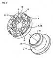
- Fig. 3 shows a perspective view of the tube locking element 5 and the bushing 4.
- the main body 8 is made of thermoplastics, whereas the first retaining means 6 and the second retaining means 7 are made up of metal.
- Tube locking element 5 is manufactured by insertion moulding, e.g. moulding thermoplastics around the metal parts.
- the first retaining means 6 consist of an annular gear 12 in form of a small tape meandring to form triangle shaped teeth 13 and connecting basis 18.
- the thermoplastic material is molded near the basis 18, whereby basis 18 and teeth 13 may include an angle other than 180°.
- the width of the tape may change in different areas of the annular gear 12. For example, near the tip of the teeth 13, the width may be larger than in the area of the basis 18.
- reinforcements 19 are provided in the main body 8 at those areas, where the basis 18 is incorporated in the main body 8.
- the abutment 11 and the areas of enlarged wall thickness serve as guiding means for the teeth 13, thus controlling their stroke.
- Fig. 4 shows a plain view of the tube locking element 5, with teeth 13, basis 18, a blade 14 of the second retaining elements 7 and the abutment 11 for the swivel stroke of teeth 13.
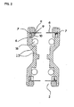
- Fig. 5a-c finally show three sectional views of the tube locking element 5 with second retaining means 7 and first retaining means 6.
- the main body 8 shows an enhanced wall thickness 9.
- no teeth 13 of the first retaining means 6 are provided.
- Fig. 5b shows the first retaining means 6 in their idle position without any tube 15 inserted. The angle enclosed between teeth 13 and basis 18 is shown.
- Fig. 5c the swivel stroke of teeth 13 is shown, which is conducted whenever a tube 15 enters the inventive tube locking element 5.
- the assembly of the inventive coupling device consists of the steps: inserting the O-ring 16 into the coupling sleeve 1 to abut against abutment 11, forcibly inserting the tube locking element 5 into the axial bore 2 of the coupling sleeve 1.
- the second retaining means 7 are pressing themselves against the inner wall of the coupling sleeve 1, preventing the tube locking element 5 from being pulled out of the coupling sleeve 1. This is possible, since the second retaining means 7 are protruding beyond the outer circumference of the main body 8.
- the bushing 4 is inserted into the central opening of tube locking element 5.
- the teeth 13 are swivelled by the bushing 4 at a certain angel as depicted in Fig. 1 or 5c .
- the teeth 13 are guided by the areas of enhanced wall thickness 9 to achieve a stable swiveling move.
- tube 15 is inserted into the bushing 4 until it abuts against abutment 11 of the coupling sleeve 1.
- Tube 15 presses O-ring 16 tightly against the inner wall of the coupling sleeve, thereby achieving a leakage free sealing.
- teeth 13 are pressing themselves thightly against the outer wall of tube 15 and hereby digging themselves into the wall. By doing so, they prevent tube 15 from being pulled out of the coupling device 1.
- bushing 4 is pushed into the central bore 2, hereby interrupting the contact of teeth 13 with tube 15, so that the latter may be easily withdrawn from the coupling sleeve 1.
- tubes with diameters of more than 0,5" may be coupled leakage free, which was not possible before. This is mainly due to the reduced number of parts in the coupling device and the reduced number of necessary seals.
Landscapes
- Engineering & Computer Science (AREA)
- General Engineering & Computer Science (AREA)
- Mechanical Engineering (AREA)
- Quick-Acting Or Multi-Walled Pipe Joints (AREA)
- Gears, Cams (AREA)
Priority Applications (8)
| Application Number | Priority Date | Filing Date | Title |
|---|---|---|---|
| AT06026185T ATE502248T1 (de) | 2006-12-18 | 2006-12-18 | Rohrkupplungsvorrichtung |
| EP06026185A EP1936251B1 (fr) | 2006-12-18 | 2006-12-18 | Dispositif de raccord de tuyau |
| DE602006020750T DE602006020750D1 (de) | 2006-12-18 | 2006-12-18 | Rohrkupplungsvorrichtung |
| AU2007334977A AU2007334977A1 (en) | 2006-12-18 | 2007-11-07 | Tube coupling device |
| PCT/EP2007/009626 WO2008074378A1 (fr) | 2006-12-18 | 2007-11-07 | Dispositif d'accouplement de tubes |
| US12/515,240 US20100045032A1 (en) | 2006-12-18 | 2007-11-07 | Tube Coupling Device |
| CNA2007800469169A CN101578470A (zh) | 2006-12-18 | 2007-11-07 | 管联结装置 |
| RU2009127326/06A RU2009127326A (ru) | 2006-12-18 | 2007-11-07 | Трубная муфта |
Applications Claiming Priority (1)
| Application Number | Priority Date | Filing Date | Title |
|---|---|---|---|
| EP06026185A EP1936251B1 (fr) | 2006-12-18 | 2006-12-18 | Dispositif de raccord de tuyau |
Publications (2)
| Publication Number | Publication Date |
|---|---|
| EP1936251A1 true EP1936251A1 (fr) | 2008-06-25 |
| EP1936251B1 EP1936251B1 (fr) | 2011-03-16 |
Family
ID=38001907
Family Applications (1)
| Application Number | Title | Priority Date | Filing Date |
|---|---|---|---|
| EP06026185A Not-in-force EP1936251B1 (fr) | 2006-12-18 | 2006-12-18 | Dispositif de raccord de tuyau |
Country Status (8)
| Country | Link |
|---|---|
| US (1) | US20100045032A1 (fr) |
| EP (1) | EP1936251B1 (fr) |
| CN (1) | CN101578470A (fr) |
| AT (1) | ATE502248T1 (fr) |
| AU (1) | AU2007334977A1 (fr) |
| DE (1) | DE602006020750D1 (fr) |
| RU (1) | RU2009127326A (fr) |
| WO (1) | WO2008074378A1 (fr) |
Cited By (1)
| Publication number | Priority date | Publication date | Assignee | Title |
|---|---|---|---|---|
| FR3001276A1 (fr) * | 2014-04-14 | 2014-07-25 | Parker Hannifin Mfg France Sas | Dispositif de raccordement assurant une continuite electrique entre tubes |
Families Citing this family (10)
| Publication number | Priority date | Publication date | Assignee | Title |
|---|---|---|---|---|
| JP5762058B2 (ja) * | 2011-03-08 | 2015-08-12 | 株式会社ディスコ | 流量調整器具 |
| US11118712B2 (en) | 2015-03-03 | 2021-09-14 | Water Socket Ltd. | Wall socket |
| IL237545A (en) * | 2015-03-03 | 2016-12-29 | Kanizo Shlomo | Wall socket |
| TWM510753U (zh) * | 2015-05-08 | 2015-10-21 | Acare Technology Co Ltd | 呼吸器結構 |
| US10774964B2 (en) * | 2015-08-27 | 2020-09-15 | Robert D. Ryan | Pipe coupling |
| DE102015122766A1 (de) * | 2015-12-23 | 2017-08-03 | Voss Automotive Gmbh | "Zahnscheibe mit mehrstegigen Haltezähnen" |
| US20190219207A1 (en) | 2018-01-16 | 2019-07-18 | Rain Bird Corporation | Push To Connect Coupling |
| CN109268601B (zh) * | 2018-11-29 | 2020-09-29 | 潍柴动力股份有限公司 | 一种气管接头 |
| WO2021010293A1 (fr) * | 2019-07-12 | 2021-01-21 | 株式会社 潤工社 | Raccord de tuyau |
| US12345359B2 (en) | 2022-10-12 | 2025-07-01 | Rain Bird Corporation | Tube coupling |
Citations (7)
| Publication number | Priority date | Publication date | Assignee | Title |
|---|---|---|---|---|
| EP0160559A1 (fr) * | 1984-04-30 | 1985-11-06 | Kabushiki Kaisha Nihon Pisco | Jonction à tubes |
| EP0751334A1 (fr) * | 1995-06-26 | 1997-01-02 | John Derek Guest | Boîtes pour raccordement de tuyaux |
| EP0890774A1 (fr) | 1997-06-12 | 1999-01-13 | John Derek Guest | Douille de serrage pour la fixation de tubes dans des boítes pour raccords de tuyaux |
| EP0933579A2 (fr) * | 1998-02-02 | 1999-08-04 | Armaturenfabrik Hermann Voss GmbH + Co. | Dispositif de connexion pour conduites |
| EP0939267A2 (fr) | 1998-02-27 | 1999-09-01 | John Derek Guest | Raccords de tuyaux |
| EP0976961A2 (fr) | 1998-07-29 | 2000-02-02 | John Derek Guest | Dispositifs de raccord de tuyaux |
| EP1209404A1 (fr) * | 2000-11-28 | 2002-05-29 | FESTO AG & Co | Dispositif de raccord pour une conduit de fluid |
Family Cites Families (5)
| Publication number | Priority date | Publication date | Assignee | Title |
|---|---|---|---|---|
| CH506743A (de) * | 1969-06-11 | 1971-04-30 | Schmid Kranz & Co Gmbh Zweigni | Rohrverbindungsmuffe für die mechanisch gesicherte Klemmbefestigung glatter Rohrenden - insbesondere kleinkalibriger Stahlrohre |
| US4188051A (en) * | 1977-04-22 | 1980-02-12 | Parker-Hannifin Corporation | Tube coupling |
| US5299838A (en) * | 1992-06-25 | 1994-04-05 | Yang Ming Tung | Pipe connection with clip assembly having pivoting plates |
| US5580100A (en) * | 1994-02-25 | 1996-12-03 | Usui Kokusai Sangyo Kaisha Ltd. | Connecting joint for plastic tube |
| DE19510193A1 (de) * | 1995-03-21 | 1996-09-26 | Voss Armaturen | Anschlußvorrichtung für Rohrleitungen |
-
2006
- 2006-12-18 AT AT06026185T patent/ATE502248T1/de not_active IP Right Cessation
- 2006-12-18 EP EP06026185A patent/EP1936251B1/fr not_active Not-in-force
- 2006-12-18 DE DE602006020750T patent/DE602006020750D1/de active Active
-
2007
- 2007-11-07 CN CNA2007800469169A patent/CN101578470A/zh active Pending
- 2007-11-07 AU AU2007334977A patent/AU2007334977A1/en not_active Abandoned
- 2007-11-07 US US12/515,240 patent/US20100045032A1/en not_active Abandoned
- 2007-11-07 RU RU2009127326/06A patent/RU2009127326A/ru not_active Application Discontinuation
- 2007-11-07 WO PCT/EP2007/009626 patent/WO2008074378A1/fr not_active Ceased
Patent Citations (7)
| Publication number | Priority date | Publication date | Assignee | Title |
|---|---|---|---|---|
| EP0160559A1 (fr) * | 1984-04-30 | 1985-11-06 | Kabushiki Kaisha Nihon Pisco | Jonction à tubes |
| EP0751334A1 (fr) * | 1995-06-26 | 1997-01-02 | John Derek Guest | Boîtes pour raccordement de tuyaux |
| EP0890774A1 (fr) | 1997-06-12 | 1999-01-13 | John Derek Guest | Douille de serrage pour la fixation de tubes dans des boítes pour raccords de tuyaux |
| EP0933579A2 (fr) * | 1998-02-02 | 1999-08-04 | Armaturenfabrik Hermann Voss GmbH + Co. | Dispositif de connexion pour conduites |
| EP0939267A2 (fr) | 1998-02-27 | 1999-09-01 | John Derek Guest | Raccords de tuyaux |
| EP0976961A2 (fr) | 1998-07-29 | 2000-02-02 | John Derek Guest | Dispositifs de raccord de tuyaux |
| EP1209404A1 (fr) * | 2000-11-28 | 2002-05-29 | FESTO AG & Co | Dispositif de raccord pour une conduit de fluid |
Cited By (4)
| Publication number | Priority date | Publication date | Assignee | Title |
|---|---|---|---|---|
| FR3001276A1 (fr) * | 2014-04-14 | 2014-07-25 | Parker Hannifin Mfg France Sas | Dispositif de raccordement assurant une continuite electrique entre tubes |
| WO2015158708A1 (fr) * | 2014-04-14 | 2015-10-22 | Parker Hannifin Manufacturing France Sas | Dispositif de raccordement assurant une continuité électrique entre tubes |
| CN106233056A (zh) * | 2014-04-14 | 2016-12-14 | 帕克汉尼芬制造业法国联合股份公司 | 用于提供管之间的电连续性的耦接装置 |
| US10374333B2 (en) | 2014-04-14 | 2019-08-06 | Parker Hannifin Manufacturing France Sas | Coupling device providing electrical continuity between tubes |
Also Published As
| Publication number | Publication date |
|---|---|
| AU2007334977A1 (en) | 2008-06-26 |
| US20100045032A1 (en) | 2010-02-25 |
| DE602006020750D1 (de) | 2011-04-28 |
| WO2008074378A1 (fr) | 2008-06-26 |
| EP1936251B1 (fr) | 2011-03-16 |
| ATE502248T1 (de) | 2011-04-15 |
| CN101578470A (zh) | 2009-11-11 |
| RU2009127326A (ru) | 2011-01-27 |
Similar Documents
| Publication | Publication Date | Title |
|---|---|---|
| US20100045032A1 (en) | Tube Coupling Device | |
| EP0449928B1 (fr) | Raccord de tubes | |
| US4561682A (en) | Quick connect coupling | |
| EP0754281B1 (fr) | Ensemble soupape | |
| CA1321807C (fr) | Raccord rapide | |
| EP1655529B1 (fr) | Raccord rapide | |
| US5425557A (en) | Apparatus for and method of attaching hoses and tubes to a fitting | |
| EP0081247B1 (fr) | Bague d'assemblage, raccord et tuyau équipé | |
| US3922011A (en) | Hose coupling | |
| EP2140191B1 (fr) | Raccord de tuyaux | |
| CA1300527C (fr) | Tuyau ondule, en plastique, a grand diametre | |
| US4260184A (en) | Fluid coupling using staple interlock | |
| US7273235B2 (en) | Toothed washer for a tube coupler device, a method of making a toothed washer, and a coupler device of the quick coupling type | |
| CA2180256C (fr) | Flexible, raccord et partie pour celui-ci ainsi que procedes pour leur fabrication | |
| US20100276922A1 (en) | Coupling assembly | |
| US20140103644A1 (en) | Coupling assembly | |
| US7850210B2 (en) | Plug-in coupling for fluid systems | |
| EP1899635B1 (fr) | Raccord de tuyau | |
| GB2250791A (en) | Quick disconnect coupler | |
| NO318506B1 (no) | Koblingsanordning for en ror eller slangedel | |
| EP3194829A1 (fr) | Raccord à tube | |
| CN101806381B (zh) | 接头与接管活动连接结构及其连接工艺和装配工具 | |
| US4429906A (en) | Female element for quick-coupling connection for flexible pipes | |
| EP2113706B1 (fr) | Connecteur d'insertion avec pièce de couplage amélioré pour maintenir un manchon de presse | |
| EP2397741B1 (fr) | Dispositif pour le raccordement de tubes |
Legal Events
| Date | Code | Title | Description |
|---|---|---|---|
| PUAI | Public reference made under article 153(3) epc to a published international application that has entered the european phase |
Free format text: ORIGINAL CODE: 0009012 |
|
| AK | Designated contracting states |
Kind code of ref document: A1 Designated state(s): AT BE BG CH CY CZ DE DK EE ES FI FR GB GR HU IE IS IT LI LT LU LV MC NL PL PT RO SE SI SK TR |
|
| AX | Request for extension of the european patent |
Extension state: AL BA HR MK RS |
|
| 17P | Request for examination filed |
Effective date: 20081229 |
|
| AKX | Designation fees paid |
Designated state(s): AT BE BG CH CY CZ DE DK EE ES FI FR GB GR HU IE IS IT LI LT LU LV MC NL PL PT RO SE SI SK TR |
|
| 17Q | First examination report despatched |
Effective date: 20090210 |
|
| GRAP | Despatch of communication of intention to grant a patent |
Free format text: ORIGINAL CODE: EPIDOSNIGR1 |
|
| GRAS | Grant fee paid |
Free format text: ORIGINAL CODE: EPIDOSNIGR3 |
|
| GRAA | (expected) grant |
Free format text: ORIGINAL CODE: 0009210 |
|
| AK | Designated contracting states |
Kind code of ref document: B1 Designated state(s): AT BE BG CH CY CZ DE DK EE ES FI FR GB GR HU IE IS IT LI LT LU LV MC NL PL PT RO SE SI SK TR |
|
| REG | Reference to a national code |
Ref country code: GB Ref legal event code: FG4D |
|
| REG | Reference to a national code |
Ref country code: CH Ref legal event code: EP |
|
| REG | Reference to a national code |
Ref country code: IE Ref legal event code: FG4D |
|
| REF | Corresponds to: |
Ref document number: 602006020750 Country of ref document: DE Date of ref document: 20110428 Kind code of ref document: P |
|
| REG | Reference to a national code |
Ref country code: DE Ref legal event code: R096 Ref document number: 602006020750 Country of ref document: DE Effective date: 20110428 |
|
| REG | Reference to a national code |
Ref country code: NL Ref legal event code: VDEP Effective date: 20110316 |
|
| PG25 | Lapsed in a contracting state [announced via postgrant information from national office to epo] |
Ref country code: LT Free format text: LAPSE BECAUSE OF FAILURE TO SUBMIT A TRANSLATION OF THE DESCRIPTION OR TO PAY THE FEE WITHIN THE PRESCRIBED TIME-LIMIT Effective date: 20110316 Ref country code: GR Free format text: LAPSE BECAUSE OF FAILURE TO SUBMIT A TRANSLATION OF THE DESCRIPTION OR TO PAY THE FEE WITHIN THE PRESCRIBED TIME-LIMIT Effective date: 20110617 Ref country code: SE Free format text: LAPSE BECAUSE OF FAILURE TO SUBMIT A TRANSLATION OF THE DESCRIPTION OR TO PAY THE FEE WITHIN THE PRESCRIBED TIME-LIMIT Effective date: 20110316 Ref country code: ES Free format text: LAPSE BECAUSE OF FAILURE TO SUBMIT A TRANSLATION OF THE DESCRIPTION OR TO PAY THE FEE WITHIN THE PRESCRIBED TIME-LIMIT Effective date: 20110627 Ref country code: LV Free format text: LAPSE BECAUSE OF FAILURE TO SUBMIT A TRANSLATION OF THE DESCRIPTION OR TO PAY THE FEE WITHIN THE PRESCRIBED TIME-LIMIT Effective date: 20110316 |
|
| LTIE | Lt: invalidation of european patent or patent extension |
Effective date: 20110316 |
|
| PG25 | Lapsed in a contracting state [announced via postgrant information from national office to epo] |
Ref country code: AT Free format text: LAPSE BECAUSE OF FAILURE TO SUBMIT A TRANSLATION OF THE DESCRIPTION OR TO PAY THE FEE WITHIN THE PRESCRIBED TIME-LIMIT Effective date: 20110316 Ref country code: BG Free format text: LAPSE BECAUSE OF FAILURE TO SUBMIT A TRANSLATION OF THE DESCRIPTION OR TO PAY THE FEE WITHIN THE PRESCRIBED TIME-LIMIT Effective date: 20110616 Ref country code: CY Free format text: LAPSE BECAUSE OF FAILURE TO SUBMIT A TRANSLATION OF THE DESCRIPTION OR TO PAY THE FEE WITHIN THE PRESCRIBED TIME-LIMIT Effective date: 20110316 Ref country code: FI Free format text: LAPSE BECAUSE OF FAILURE TO SUBMIT A TRANSLATION OF THE DESCRIPTION OR TO PAY THE FEE WITHIN THE PRESCRIBED TIME-LIMIT Effective date: 20110316 Ref country code: SI Free format text: LAPSE BECAUSE OF FAILURE TO SUBMIT A TRANSLATION OF THE DESCRIPTION OR TO PAY THE FEE WITHIN THE PRESCRIBED TIME-LIMIT Effective date: 20110316 |
|
| PG25 | Lapsed in a contracting state [announced via postgrant information from national office to epo] |
Ref country code: BE Free format text: LAPSE BECAUSE OF FAILURE TO SUBMIT A TRANSLATION OF THE DESCRIPTION OR TO PAY THE FEE WITHIN THE PRESCRIBED TIME-LIMIT Effective date: 20110316 |
|
| PG25 | Lapsed in a contracting state [announced via postgrant information from national office to epo] |
Ref country code: PT Free format text: LAPSE BECAUSE OF FAILURE TO SUBMIT A TRANSLATION OF THE DESCRIPTION OR TO PAY THE FEE WITHIN THE PRESCRIBED TIME-LIMIT Effective date: 20110718 Ref country code: EE Free format text: LAPSE BECAUSE OF FAILURE TO SUBMIT A TRANSLATION OF THE DESCRIPTION OR TO PAY THE FEE WITHIN THE PRESCRIBED TIME-LIMIT Effective date: 20110316 |
|
| PG25 | Lapsed in a contracting state [announced via postgrant information from national office to epo] |
Ref country code: RO Free format text: LAPSE BECAUSE OF FAILURE TO SUBMIT A TRANSLATION OF THE DESCRIPTION OR TO PAY THE FEE WITHIN THE PRESCRIBED TIME-LIMIT Effective date: 20110316 Ref country code: SK Free format text: LAPSE BECAUSE OF FAILURE TO SUBMIT A TRANSLATION OF THE DESCRIPTION OR TO PAY THE FEE WITHIN THE PRESCRIBED TIME-LIMIT Effective date: 20110316 Ref country code: CZ Free format text: LAPSE BECAUSE OF FAILURE TO SUBMIT A TRANSLATION OF THE DESCRIPTION OR TO PAY THE FEE WITHIN THE PRESCRIBED TIME-LIMIT Effective date: 20110316 Ref country code: IS Free format text: LAPSE BECAUSE OF FAILURE TO SUBMIT A TRANSLATION OF THE DESCRIPTION OR TO PAY THE FEE WITHIN THE PRESCRIBED TIME-LIMIT Effective date: 20110716 |
|
| PG25 | Lapsed in a contracting state [announced via postgrant information from national office to epo] |
Ref country code: NL Free format text: LAPSE BECAUSE OF FAILURE TO SUBMIT A TRANSLATION OF THE DESCRIPTION OR TO PAY THE FEE WITHIN THE PRESCRIBED TIME-LIMIT Effective date: 20110316 |
|
| PLBE | No opposition filed within time limit |
Free format text: ORIGINAL CODE: 0009261 |
|
| STAA | Information on the status of an ep patent application or granted ep patent |
Free format text: STATUS: NO OPPOSITION FILED WITHIN TIME LIMIT |
|
| 26N | No opposition filed |
Effective date: 20111219 |
|
| PG25 | Lapsed in a contracting state [announced via postgrant information from national office to epo] |
Ref country code: PL Free format text: LAPSE BECAUSE OF FAILURE TO SUBMIT A TRANSLATION OF THE DESCRIPTION OR TO PAY THE FEE WITHIN THE PRESCRIBED TIME-LIMIT Effective date: 20110316 Ref country code: DK Free format text: LAPSE BECAUSE OF FAILURE TO SUBMIT A TRANSLATION OF THE DESCRIPTION OR TO PAY THE FEE WITHIN THE PRESCRIBED TIME-LIMIT Effective date: 20110316 |
|
| REG | Reference to a national code |
Ref country code: DE Ref legal event code: R097 Ref document number: 602006020750 Country of ref document: DE Effective date: 20111219 |
|
| PG25 | Lapsed in a contracting state [announced via postgrant information from national office to epo] |
Ref country code: IT Free format text: LAPSE BECAUSE OF FAILURE TO SUBMIT A TRANSLATION OF THE DESCRIPTION OR TO PAY THE FEE WITHIN THE PRESCRIBED TIME-LIMIT Effective date: 20110316 |
|
| PG25 | Lapsed in a contracting state [announced via postgrant information from national office to epo] |
Ref country code: MC Free format text: LAPSE BECAUSE OF NON-PAYMENT OF DUE FEES Effective date: 20111231 |
|
| REG | Reference to a national code |
Ref country code: CH Ref legal event code: PL |
|
| REG | Reference to a national code |
Ref country code: FR Ref legal event code: ST Effective date: 20120831 |
|
| REG | Reference to a national code |
Ref country code: IE Ref legal event code: MM4A |
|
| PG25 | Lapsed in a contracting state [announced via postgrant information from national office to epo] |
Ref country code: LI Free format text: LAPSE BECAUSE OF NON-PAYMENT OF DUE FEES Effective date: 20111231 Ref country code: CH Free format text: LAPSE BECAUSE OF NON-PAYMENT OF DUE FEES Effective date: 20111231 Ref country code: IE Free format text: LAPSE BECAUSE OF NON-PAYMENT OF DUE FEES Effective date: 20111218 |
|
| PG25 | Lapsed in a contracting state [announced via postgrant information from national office to epo] |
Ref country code: FR Free format text: LAPSE BECAUSE OF NON-PAYMENT OF DUE FEES Effective date: 20120102 |
|
| PGFP | Annual fee paid to national office [announced via postgrant information from national office to epo] |
Ref country code: DE Payment date: 20130122 Year of fee payment: 7 Ref country code: GB Payment date: 20130122 Year of fee payment: 7 |
|
| PG25 | Lapsed in a contracting state [announced via postgrant information from national office to epo] |
Ref country code: LU Free format text: LAPSE BECAUSE OF NON-PAYMENT OF DUE FEES Effective date: 20111218 |
|
| PG25 | Lapsed in a contracting state [announced via postgrant information from national office to epo] |
Ref country code: TR Free format text: LAPSE BECAUSE OF FAILURE TO SUBMIT A TRANSLATION OF THE DESCRIPTION OR TO PAY THE FEE WITHIN THE PRESCRIBED TIME-LIMIT Effective date: 20110316 |
|
| PG25 | Lapsed in a contracting state [announced via postgrant information from national office to epo] |
Ref country code: HU Free format text: LAPSE BECAUSE OF FAILURE TO SUBMIT A TRANSLATION OF THE DESCRIPTION OR TO PAY THE FEE WITHIN THE PRESCRIBED TIME-LIMIT Effective date: 20110316 |
|
| REG | Reference to a national code |
Ref country code: DE Ref legal event code: R119 Ref document number: 602006020750 Country of ref document: DE |
|
| GBPC | Gb: european patent ceased through non-payment of renewal fee |
Effective date: 20131218 |
|
| REG | Reference to a national code |
Ref country code: DE Ref legal event code: R119 Ref document number: 602006020750 Country of ref document: DE Effective date: 20140701 |
|
| PG25 | Lapsed in a contracting state [announced via postgrant information from national office to epo] |
Ref country code: DE Free format text: LAPSE BECAUSE OF NON-PAYMENT OF DUE FEES Effective date: 20140701 |
|
| PG25 | Lapsed in a contracting state [announced via postgrant information from national office to epo] |
Ref country code: GB Free format text: LAPSE BECAUSE OF NON-PAYMENT OF DUE FEES Effective date: 20131218 |