EP1936259A1 - Montagesystem zur Montage von Leuchtdioden in einem Gehäuse einer Lichteinheit oder eines Fahrzeugscheinwerfers - Google Patents
Montagesystem zur Montage von Leuchtdioden in einem Gehäuse einer Lichteinheit oder eines Fahrzeugscheinwerfers Download PDFInfo
- Publication number
- EP1936259A1 EP1936259A1 EP07450187A EP07450187A EP1936259A1 EP 1936259 A1 EP1936259 A1 EP 1936259A1 EP 07450187 A EP07450187 A EP 07450187A EP 07450187 A EP07450187 A EP 07450187A EP 1936259 A1 EP1936259 A1 EP 1936259A1
- Authority
- EP
- European Patent Office
- Prior art keywords
- mounting
- kop
- spi
- mounting system
- optical element
- Prior art date
- Legal status (The legal status is an assumption and is not a legal conclusion. Google has not performed a legal analysis and makes no representation as to the accuracy of the status listed.)
- Granted
Links
Images


Classifications
-
- B—PERFORMING OPERATIONS; TRANSPORTING
- B60—VEHICLES IN GENERAL
- B60Q—ARRANGEMENT OF SIGNALLING OR LIGHTING DEVICES, THE MOUNTING OR SUPPORTING THEREOF OR CIRCUITS THEREFOR, FOR VEHICLES IN GENERAL
- B60Q1/00—Arrangement of optical signalling or lighting devices, the mounting or supporting thereof or circuits therefor
- B60Q1/02—Arrangement of optical signalling or lighting devices, the mounting or supporting thereof or circuits therefor the devices being primarily intended to illuminate the way ahead or to illuminate other areas of way or environments
- B60Q1/04—Arrangement of optical signalling or lighting devices, the mounting or supporting thereof or circuits therefor the devices being primarily intended to illuminate the way ahead or to illuminate other areas of way or environments the devices being headlights
- B60Q1/06—Arrangement of optical signalling or lighting devices, the mounting or supporting thereof or circuits therefor the devices being primarily intended to illuminate the way ahead or to illuminate other areas of way or environments the devices being headlights adjustable, e.g. remotely-controlled from inside vehicle
- B60Q1/068—Arrangement of optical signalling or lighting devices, the mounting or supporting thereof or circuits therefor the devices being primarily intended to illuminate the way ahead or to illuminate other areas of way or environments the devices being headlights adjustable, e.g. remotely-controlled from inside vehicle by mechanical means
- B60Q1/0683—Adjustable by rotation of a screw
-
- F—MECHANICAL ENGINEERING; LIGHTING; HEATING; WEAPONS; BLASTING
- F21—LIGHTING
- F21S—NON-PORTABLE LIGHTING DEVICES; SYSTEMS THEREOF; VEHICLE LIGHTING DEVICES SPECIALLY ADAPTED FOR VEHICLE EXTERIORS
- F21S41/00—Illuminating devices specially adapted for vehicle exteriors, e.g. headlamps
- F21S41/10—Illuminating devices specially adapted for vehicle exteriors, e.g. headlamps characterised by the light source
- F21S41/14—Illuminating devices specially adapted for vehicle exteriors, e.g. headlamps characterised by the light source characterised by the type of light source
- F21S41/141—Light emitting diodes [LED]
- F21S41/147—Light emitting diodes [LED] the main emission direction of the LED being angled to the optical axis of the illuminating device
- F21S41/148—Light emitting diodes [LED] the main emission direction of the LED being angled to the optical axis of the illuminating device the main emission direction of the LED being perpendicular to the optical axis
-
- F—MECHANICAL ENGINEERING; LIGHTING; HEATING; WEAPONS; BLASTING
- F21—LIGHTING
- F21S—NON-PORTABLE LIGHTING DEVICES; SYSTEMS THEREOF; VEHICLE LIGHTING DEVICES SPECIALLY ADAPTED FOR VEHICLE EXTERIORS
- F21S41/00—Illuminating devices specially adapted for vehicle exteriors, e.g. headlamps
- F21S41/10—Illuminating devices specially adapted for vehicle exteriors, e.g. headlamps characterised by the light source
- F21S41/19—Attachment of light sources or lamp holders
-
- F—MECHANICAL ENGINEERING; LIGHTING; HEATING; WEAPONS; BLASTING
- F21—LIGHTING
- F21V—FUNCTIONAL FEATURES OR DETAILS OF LIGHTING DEVICES OR SYSTEMS THEREOF; STRUCTURAL COMBINATIONS OF LIGHTING DEVICES WITH OTHER ARTICLES, NOT OTHERWISE PROVIDED FOR
- F21V19/00—Fastening of light sources or lamp holders
- F21V19/001—Fastening of light sources or lamp holders the light sources being semiconductors devices, e.g. LEDs
-
- F—MECHANICAL ENGINEERING; LIGHTING; HEATING; WEAPONS; BLASTING
- F21—LIGHTING
- F21V—FUNCTIONAL FEATURES OR DETAILS OF LIGHTING DEVICES OR SYSTEMS THEREOF; STRUCTURAL COMBINATIONS OF LIGHTING DEVICES WITH OTHER ARTICLES, NOT OTHERWISE PROVIDED FOR
- F21V19/00—Fastening of light sources or lamp holders
- F21V19/04—Fastening of light sources or lamp holders with provision for changing light source, e.g. turret
-
- F—MECHANICAL ENGINEERING; LIGHTING; HEATING; WEAPONS; BLASTING
- F21—LIGHTING
- F21Y—INDEXING SCHEME ASSOCIATED WITH SUBCLASSES F21K, F21L, F21S and F21V, RELATING TO THE FORM OR THE KIND OF THE LIGHT SOURCES OR OF THE COLOUR OF THE LIGHT EMITTED
- F21Y2115/00—Light-generating elements of semiconductor light sources
- F21Y2115/10—Light-emitting diodes [LED]
Definitions
- the invention relates to a mounting system for mounting one or more light emitting diodes in a housing of a light unit or a vehicle headlamp, wherein the mounting system comprises a mounting member, and wherein the at least one light emitting diode is arranged on the mounting member, and further arranged at least one optical element on the mounting member is, and light is emitted from the at least one light emitting diode via the at least one optical element in the outer space of the light unit or the vehicle headlamp.
- Conventional headlights for motor vehicles are equipped with light sources, such as halogen and xenon lamps.
- a socket is provided, which allows a simple change of the light source.
- Optical adjustments to reflectors, lenses, etc., which interact with the light source are not affected by the change of the light source, since the light source is matched with their tolerances on the headlight.
- the light emitting diodes are arranged directly on a mounting element on which all optically necessary components are optimally positioned to the one or more LEDs.
- the optical components are correctly positioned to each other and the mounting element must then be adjusted when installed in the headlight, so that the legal requirements can be met to the photograph.
- the adjustment When changing the mounting element, the adjustment remains exactly in the position in which it was located with inserted mounting element.
- the optical settings for the optical element are "stored", and upon insertion of a new mounting element, the optical element on the new mounting element adopts the optical adjustments from the adjustment element.
- the "storage" of the optical settings is carried out particularly expedient with a mounting system in which on the housing an accessible from the outside of the housing adjusting screw is mounted, which cooperates with the adjustment such that upon rotation of the adjusting screw, the adjustment is moved in the longitudinal direction and the Setting in the desired position can be fixed.
- the adjusting screw is mounted against rotation in the housing, since it is not accessible without tools. With a corresponding tool, the adjusting screw can then be adjusted, whereby the adjustment moves accordingly and assumes the desired position.
- one of the two coupling element has a receiving opening, in which the other coupling element is releasably inserted, wherein in the inserted state, the sliding movement of a coupling element without play in a pivoting movement of the other coupling element is implemented.
- the optical settings of the adjusting element are transferred exactly to the optical element in this way.
- a concrete advantageous embodiment of the invention is characterized in that the one coupling element is a shaft which is parallel to the pivot axis, and the receiving opening of the other coupling element has a shaft which at least partially surrounds this shaft configuration.
- This variant is stable and can be implemented easily and inexpensively.
- a particularly stable backlash-free interaction of the components results when the one coupling element has a ball head, and the other coupling element has a ball head at least partially encompassing receiving opening.
- the first coupling element is arranged outside the pivot axis of the optical element.
- the two coupling elements when inserting a mounting element, the two coupling elements simply reach each other in the correct position, it is further provided that the coupling element with the receiving opening has a catching device for catching the other coupling element during assembly of the mounting system. Even if the optical element is in an extreme position outside the desired position when inserting the mounting element, it is simply possible to bring the two coupling elements closer to each other and to couple them together.
- one or more guide elements are integrally formed on the adjusting element, by means of which the adjusting element is slidably mounted in a guide in or on the housing.
- At least one guide element is elastically formed on the adjusting element or is designed to be elastic.
- the adjustment element with the guide elements in the guide e.g. pressed a guide rail, whereby a play-free storage is given and a shake is prevented.
- the at least one guide element is designed as a guide leaflet.
- the optical element in a specific embodiment is a reflector, e.g. a concave mirror or a plane mirror.
- the optical element comprises at least one lens.
- a lens or a scattering glass is arranged in the light exit direction in front of the optical element.
- the displacement direction of the at least one adjusting element is substantially normal to the mounting direction of the mounting element.
- the adjustment is not in the way of insertion of the mounting element in the way and between the coupling elements can be easily made the necessary contact.
- the figures show a mounting system SYS according to the invention for mounting one or more LEDs LIQ in a housing GEH a light unit or a vehicle headlamp.
- the mounting system SYS comprises a mounting element MON, which is designed as a cover, with which the housing GEH is closed by placing.
- the connection and optionally sealing between housing GEH and mounting element MON is carried out in a known manner and will not be described here.
- the at least one light-emitting diode LIQ is arranged on an LED print, not shown in the drawing, which is placed on the mounting member MON.
- an optical element SPI is arranged on the mounting element MON, and light from the at least one light-emitting diode LIQ is emitted via the optical element SPI into the outer space of the light unit or of the vehicle headlight.
- the optical element is a plane mirror SPI.
- the mirror SPI is held by a holder HAL, which further holds in this representation still another optics STG in the form of a scattering glass (with or without optical elements) or a lens.
- the holder HAL is mounted on the mounting element MON.
- the mirror can also be a curved mirror (reflector), or a lens / diffusing glass or a combined optical element made of mirror (flat or curved) and lens or scattered glass.
- the reference character X denotes the optical axis of the system
- Y denotes the mounting direction in which the mounting member MON is placed on the housing GEH.
- the optical element in the form of a mirror SPI is pivotably mounted on the holder HAL by means of pins ZAP about a swiveling axis ACH.
- pivoting the optical element SPI this coupled with an adjustment KOP such that a translational movement of the at least one adjusting element KOP is converted into a pivoting movement of the optical element SPI about its pivot axis ACH.
- the system SYS according to the invention can be realized in a simple and reliable manner, as shown, with only one adjustment element KOP.
- a plurality of such adjustment elements can be coupled to one another such that the effect according to the invention is achieved; This can be beneficial if the point of application for the adjusting screw is unfavorable. In general, it is better if only one adjustment element is used as shown.
- the optical element SPI and the setting element KOP are coupled to each other via a first coupling element KUP1, which is fixedly connected to the optical element SPI, and a second coupling element KUP2, which is fixedly connected to the adjusting element KOP.
- the coupling of the first and second coupling element KUP1, KUP2 is detachable. Furthermore, the adjustment element KOP is in the housing GEH of the light unit or of the vehicle headlight in a direction X back and forth longitudinally displaceable in the two spatial axes normal to the direction of displacement X but immovably arranged and in a predetermined position, regardless of the at least one optical element SPI fixable. In this position, the adjustment element KOP also remains when the mounting element MON is removed. As a result, the first coupling element KOP1 is also in a position which corresponds to the coupled position, whereby the optical settings are "stored" and transmitted to a newly inserted optical element.
- the adjustment element KOP When changing the mounting element thus the adjustment element KOP remains exactly in that position in which it was with inserted mounting element MON.
- the optical settings for the optical element are "stored", and upon insertion of a new mounting element, the optical element on the new mounting element adopts the optical adjustments from the adjustment element.
- the "storage" of the optical settings is carried out in a particularly advantageous embodiment as shown in the figures with a mounting system SYS, in which on the housing GEH an accessible from the housing outside GES adjusting screw ESS is stored ( FIGS. 4 and 5 ), which interacts with the adjusting element KOP such that, when the adjusting screw ESS is turned, the adjusting element KOP is displaced in the longitudinal direction, depending on the direction of rotation, back or forth parallel to the optical axis OPA and the adjusting element KOP can be fixed in the desired position.
- a mounting system SYS in which on the housing GEH an accessible from the housing outside GES adjusting screw ESS is stored ( FIGS. 4 and 5 ), which interacts with the adjusting element KOP such that, when the adjusting screw ESS is turned, the adjusting element KOP is displaced in the longitudinal direction, depending on the direction of rotation, back or forth parallel to the optical axis OPA and the adjusting element KOP can be fixed in the desired position.
- the adjusting screw ESS is mounted against rotation in the housing GEH, since it is not accessible without tools. With a corresponding tool, the adjusting screw ESS can then be adjusted, whereby the adjusting element KOP moves accordingly and assumes the desired position.
- one of the two coupling element KUP2 has a receiving opening KUPa, in which the other coupling element KUP1 is detachably insertable, wherein in the inserted state, the displacement movement of a coupling element KUP2 play in a Swiveling movement of the other coupling element KUP1 is implemented.
- coupling element KUP2 which is arranged on the adjusting element KOP, has the receiving opening KUPa.
- the further coupling element KUP1 is a shaft which runs parallel to the swiveling axis ACH, and the receiving opening KUPa of the coupling element KUP2 on the adjusting element KOP has a shaft which surrounds this shaft at least in sections on the circumference.
- the translational movement of the adjusting element KOP is converted into a pivoting movement of the optical element SPI
- the coupling elements KUP1, KUP2 are arranged in the assembled state outside the pivot axis ACH of the optical element SPI.
- the two coupling elements when inserting a mounting element, the two coupling elements simply reach each other in the correct position, it is further provided that the coupling element KUP2 with the receiving opening KUPa a safety catch FAN for trapping the other coupling element KUP1 during assembly of the mounting system SYS has. Even if the optical element SPI is in an extreme position outside the desired position when inserting the mounting element MON, it is nevertheless simply possible to bring the two coupling elements KUP1, KUP2 closer to each other and to couple them together.
- two guide elements FUE1, FUE2 are integrally formed on the adjusting element KOP, by means of which the adjusting element KOP in a guide (not shown) is displaceably mounted in the housing GEH.
- the guide element FUE1 facing away from the coupling element KUP2 is elastically formed on the adjusting element KOP via an elastic section FUel.
- the adjustment element KOP with the guide elements FUE1, FUE2 in the guide e.g. pressed a guide rail, whereby a play-free storage is given and a shake is prevented.
- the guide elements FUE1, FUE2 themselves are designed as guide leaflets.
- the displacement direction X of the at least one adjustment element KOP is substantially normal to the mounting direction Y of the mounting member MON.
- the adjustment is not in the way of insertion of the mounting element in the way and between the coupling elements can be easily made the necessary contact.
Landscapes
- Engineering & Computer Science (AREA)
- General Engineering & Computer Science (AREA)
- Physics & Mathematics (AREA)
- Microelectronics & Electronic Packaging (AREA)
- Optics & Photonics (AREA)
- Mechanical Engineering (AREA)
- Non-Portable Lighting Devices Or Systems Thereof (AREA)
- Lighting Device Outwards From Vehicle And Optical Signal (AREA)
Abstract
Description
- Die Erfindung betrifft ein Montagesystem zur Montage von einer oder mehreren Leuchtdioden in einem Gehäuse einer Lichteinheit oder eines Fahrzeugscheinwerfers, wobei das Montagesystem ein Montageelement umfasst, und wobei die zumindest eine Leuchtdiode auf dem Montageelement angeordnet ist, und weiters zumindest ein optisches Element auf dem Montageelement angeordnet ist, und Licht von der zumindest einen Leuchtdiode über das zumindest eine optische Element in den Außenraum der Lichteinheit bzw. des Fahrzeugscheinwerfers emittiert wird.
- Herkömmliche Scheinwerfer für Kraftfahrzeuge sind mit Lichtquellen, wie Halogen- und Xenonlampen bestückt. Zur Halterung dieser Lichtquellen ist eine Fassung vorgesehen, welche ein einfaches Wechseln der Lichtquelle ermöglicht. Optische Einstellungen an Reflektoren, Linsen etc., welche mit der Lichtquelle zusammenwirken, werden durch den Wechsel der Lichtquelle nicht beeinflusst, da die Lichtquelle mit ihren Toleranzen auf den Scheinwerfer abgestimmt ist.
- Die Verwendung von Leuchtdioden stellt im Gegensatz dazu wesentlich höhere Anforderungen an die Toleranzen und die Einbausituation als dies bei herkömmlichen Scheinwerfern der Fall ist.
- Aus diesem Grund werden die Leuchtdioden direkt auf einem Montageelement angeordnet, auf welchem alle optisch notwendigen Bauteile optimal zu der oder den Leuchtdioden positioniert werden. Auf dem Montageelement sind die optischen Bauteile zueinander richtig positioniert und das Montageelement muss dann beim Einbau in den Scheinwerfer noch justiert werden, damit die gesetzlichen Erfordernisse an das Lichtbild erfüllt werden können.
- Ein solches Justieren des Montagelementes ist zeitaufwändig und umständlich und ist insbesondere bei der Verwendung von Infrarot-Leuchtdioden mit einem erhöhten Aufwand verbunden.
- Außerdem muss bei einem Wechsel einer Leuchtdiode, die mit dem Wechsel des Montageelementes verbunden ist, das neue Montageelement wiederum justiert werden.
- Es ist eine Aufgabe der Erfindung, ein Wechseln von einer oder mehreren Leuchtdioden zu ermögliche, ohne dass die lichttechnischen Einstellungen neuerlich vorgenommen werden müssen.
- Diese Aufgabe wird mit einem eingangs erwähnten System dadurch gelöst, dass erfindungsgemäß
- a) das zumindest eine optische Element um zumindest eine Verschwenkachse verschwenkbar ist,
- b) und zum Verschwenken des zumindest einen optischen Elementes dieses mit zumindest einem Einstellelement derart gekoppelt ist, dass eine Translationsbewegung des zumindest einen Einstellelementes in eine Verschwenkbewegung des zumindest einen optischen Elementes um seine Verschwenkachse umgesetzt wird,
- Bei einem Wechsel des Montageelementes verbleibt das Einstellelement exakt in jener Position, in welcher es sich bei eingesetztem Montageelement befand. Es werden somit die optischen Einstellungen für das optische Element "gespeichert", und bei einem Einsetzen eines neuen Montageelementes übernimmt das optische Element auf dem neuen Montageelement die optischen Einstellungen von dem Einstellelement.
- Die "Speicherung" der optischen Einstellungen erfolgt dabei besonders zweckmäßig mit einem Montagesystem, bei welchem an dem Gehäuse eine von der Gehäuseaußenseite zugängliche Einstellschraube gelagert ist, welche mit dem Einstellelement derart zusammenwirkt, dass bei einem Verdrehen der Einstellschraube das Einstellelement in Längsrichtung verschoben wird und das Einstellelement in der gewünschten Position fixierbar ist.
- Die Einstellschraube ist in dem Gehäuse verdrehsicher gelagert, da sie ohne Werkzeug nicht zugänglich ist. Mit einem entsprechenden Werkzeug kann die Einstellschraube dann verstellt werden, wodurch sich das Einstellelement entsprechend bewegt und die gewünschte Position einnimmt.
- Auch andere Fixierelemente als eine Einstellschraube sind denkbar, z.B. ein Klemmelement, welches durch entsprechende Krafteinwirkung mit einem Werkzeug in einer Führung verschoben werden kann, durch die Klemmwirkung sonst aber hält. Die Verwendung einer Einstellschraube hat aber den Vorteil, dass mit ihr besonders exakt die Position eingestellt werden kann und in beide Verschieberichtung des Einstellelementes die Verstellung gleich einfach erfolgt.
- Um ein besonders einfaches Lösen und wieder miteinander Verbinden zu erlauben, ist weiters vorgesehen, dass eines der beiden Kupplungselement eine Aufnahmeöffnung aufweist, in welche das andere Kupplungselement lösbar einsetzbar ist, wobei in eingesetztem Zustand die Verschiebebewegung des einen Kupplungselementes spielfrei in eine Verschwenkbewegung des anderen Kupplungselementes umgesetzt wird.
- Außerdem werden im eingesetzten Zustand die optischen Einstellungen des Einstellelementes auf diese Weise exakt auf das optische Element übertragen.
- Eine konkrete vorteilhafte Ausgestaltungsform der Erfindung zeichnet sich dadurch aus, dass das eine Kupplungselement eine Welle ist, welche parallel zu der Verschwenkachse verläuft, und die Aufnahmeöffnung des anderen Kupplungselementes ein diese Welle zumindest abschnittsweise am Umfang umgreifende Ausgestaltung aufweist.
- Diese Variante ist stabil und lässt sich einfach und kostengünstig realisieren.
- Ein besonders stabiles spielfreies Zusammenwirken der Bauteile ergibt sich, wenn das eine Kupplungselement einen Kugelkopf aufweist, und das andere Kupplungselement eine diesen Kugelkopf zumindest teilweise umgreifende Aufnahmeöffnung aufweist.
- Damit die Translationsbewegung des Einstellelementes in eine Verschwenkbewegung des optischen Elementes umgesetzt wird, ist weiters vorgesehen, dass das erste Kupplungselement außerhalb der Verschwenkachse des optischen Elementes angeordnet ist.
- Damit beim Einsetzen eines Montageelementes die beiden Kupplungselemente einfach in die richtige Position zueinander gelangen, ist weiters vorgesehen, dass das Kupplungselement mit der Aufnahmeöffnung eine Fangvorrichtung zum Einfangen des anderen Kupplungselementes beim Zusammenbau des Montagesystems aufweist. Auch wenn beim Einsetzen des Montageelementes das optische Element sich in einer Extremposition außerhalb der gewünschten Position befindet, ist es doch einfach möglich, die beiden Kupplungselemente einander anzunähern und diese miteinander zu koppeln.
- Damit eine gleichmäßige Bewegung und ein stabiler Sitz des Einstellelementes in dem Gehäuse gewährleistet ist, ist weiters vorgesehen, dass an dem Einstellelement ein oder mehrere Führungselemente angeformt sind, mittels welcher das Einstellelement in einer Führung in oder an dem Gehäuse verschiebbar gelagert ist.
- Außerdem kann auch noch vorgesehen sein, dass zumindest ein Führungselement an dem Einstellelement elastisch angeformt ist oder elastisch ausgebildet ist. Dadurch wird das Einstellelement mit den Führungselementen in die Führung, z.B. eine Führungsschiene gedrückt, wodurch eine spielfreie Lagerung gegeben ist und ein Wackeln verhindert ist.
- Beispielsweise ist das zumindest eine Führungselement als Führungsblättchen ausgebildet.
- Das optische Element ist bei einer konkreten Ausführungsform ein Reflektor, z.B. ein Hohlspiegel oder eine ebener Spiegel.
- Außerdem kann vorgesehen sein, dass das optische Element zumindest eine Linse umfasst.
- Zweckmäßig kann es auch sein, wenn in Lichtaustrittsrichtung vor dem optischen Element eine Linse oder ein Streuglas angeordnet ist.
- Um eine einfache Montage zu erlauben, ist vorgesehen, dass die Verschieberichtung des zumindest einen Einstellelementes im Wesentlichen normal auf die Montagerichtung des Montageelementes steht. Bei dieser Ausgestaltung ist das Einstellelement bei einem Einsetzen des Montageelementes nicht im Weg und zwischen den Kupplungselementen kann einfach der notwendige Kontakt hergestellt werden.
- Im Folgenden ist die Erfindung an Hand der Zeichnung näher erläutert. In dieser zeigt
-
Fig. 1 eine erste perspektivische Darstellung eines erfindungsgemäßen Systems, -
Fig. 2 eine zweite perspektivische Ansicht des Systems ausFigur 1 , -
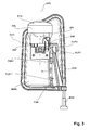
Fig. 3 eine Draufsicht auf ein System ausFigur 1 und 2 entgegen der Montagerichtung des Montagelementes, -
Fig. 4 eine erste Seitenansicht des erfindungsgemäßen Systems, -
Fig. 5 eine zweite Seitenansicht des erfindungsgemäßen Systems von der inFigur 4 gezeigten Seite gegenüberliegenden Seite, -
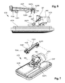
Fig. 6 das Montageelement und das davon getrennte Einstellelement in einer Seitenansicht entsprechendFigur 5 ohne Gehäuse und ohne Einstellschraube, und -
Fig. 7 die Darstellung ausFigur 6 in einer perspektivischen Ansicht. - Die Figuren zeigen ein Montagesystem SYS entsprechend der Erfindung zur Montage von einer oder mehreren Leuchtdioden LIQ in einem Gehäuse GEH einer Lichteinheit oder eines Fahrzeugscheinwerfers.
- Das Montagesystem SYS umfasst ein Montageelement MON, das als Deckel ausgebildet ist, mit dem das Gehäuse GEH durch Aufsetzen verschlossen wird. Die Verbindung und gegebenenfalls Abdichtung zwischen Gehäuse GEH und Montageelement MON erfolgt dabei auf bekannte Art und Weise und wird hier nicht näher erläutert.
- Die zumindest eine Leuchtdiode LIQ ist auf einem in der Zeichnung nicht dargestellten LED-Print angeordnet, welcher auf dem Montageelement MON platziert ist.
- Außerdem ist auf dem Montageelement MON ein optisches Element SPI angeordnet, und Licht von der zumindest einen Leuchtdiode LIQ wird über das optische Element SPI in den Außenraum der Lichteinheit bzw. des Fahrzeugscheinwerfers emittiert.
- In der gezeigten Darstellung ist das optische Element ein ebener Spiegel SPI. Der Spiegel SPI ist von einer Halterung HAL gehalten, welche weiters in dieser Darstellung noch eine weitere Optik STG in Form eines Streuglases (mit oder ohne optische Elemente) oder eine Linse hält. Die Halterung HAL ist auf dem Montageelement MON befestigt.
- Bei dem Spiegel kann es sich in einer anderen Ausgestaltung natürlich auch um einen gekrümmten Spiegel (Reflektor) handeln, oder um eine Linse/Streuglas bzw. um ein kombiniertes optisches Element aus Spiegel (eben oder gekrümmt) und Linse bzw. Streuglas.
- Mit dem Bezugszeichen X ist die optische Achse des Systems bezeichnet, Y bezeichnet die Montagerichtung, in welcher das Montageelement MON auf das Gehäuse GEH aufgesetzt wird.
- Das optische Element in Form eines Spiegels SPI ist mittels Zapfen ZAP um eine Verschwenkachse ACH an der Halterung HAL verschwenkbar gelagert. Zum Verschwenken des optischen Elementes SPI dieses mit einem Einstellelement KOP derart gekoppelt, dass eine Translationsbewegung des zumindest einen Einstellelementes KOP in eine Verschwenkbewegung des optischen Elementes SPI um seine Verschwenkachse ACH umgesetzt wird.
- Einfach und zuverlässig lässt sich das erfindungsgemäße System SYS wie gezeigt mit nur einem Einstellelement KOP realisieren. Natürlich können aber auch mehrere solche Einstellelemente derart miteinander gekoppelt sein, dass der erfindungsgemäße Effekt erzielt wird; dies kann günstig sein, wenn der Angriffspunkt für die Einstellschraube ungünstig liegt. In der Regel ist es aber besser, wenn lediglich ein Einstellelement wie gezeigt verwendet wird.
- Das optische Element SPI und das Einstellelement KOP sind dabei über ein erstes Kupplungselement KUP1, welches fest mit dem optischen Element SPI verbunden ist, und ein zweites Kupplungselement KUP2, welches fest mit dem Einstellelement KOP verbunden ist, miteinander gekoppelt.
- Die Kopplung von erstem und zweitem Kupplungselement KUP1, KUP2 ist lösbar ist. Weiters ist das Einstellelement KOP in dem Gehäuse GEH der Lichteinheit bzw. des Fahrzeugscheinwerfers in einer Richtung X vor und zurück längsverschiebbar, in den beiden Raumachsen normal auf die Verschieberichtung X aber unbeweglich angeordnet und in einer vorgebbaren Position, unabhängig von dem zumindest einen optischen Element SPI, fixierbar. In dieser Position verbleibt das Einstellelement KOP auch, wenn das Montageelement MON entfernt wird. Dadurch befindet sich auch das erste Kupplungselement KOP1 in einer Position, welcher der gekoppelten Position entspricht, wodurch die optischen Einstellungen "gespeichert" werden und auf ein neu eingesetztes optisches Element übertragen werden.
- Bei einem Wechsel des Montageelementes verbleibt somit das Einstellelement KOP exakt in jener Position, in welcher es sich bei eingesetztem Montageelement MON befand. Es werden somit die optischen Einstellungen für das optische Element "gespeichert", und bei einem Einsetzen eines neuen Montageelementes übernimmt das optische Element auf dem neuen Montageelement die optischen Einstellungen von dem Einstellelement.
- Die "Speicherung" der optischen Einstellungen erfolgt bei einer besonders zweckmäßigen Ausführungsform wie in den Figuren gezeigt mit einem Montagesystem SYS, bei welchem an dem Gehäuse GEH eine von der Gehäuseaußenseite GES zugängliche Einstellschraube ESS gelagert ist (
Figur 4 und 5 ), welche mit dem Einstellelement KOP derart zusammenwirkt, dass bei einem Verdrehen der Einstellschraube ESS das Einstellelement KOP in Längsrichtung je nach Drehrichtung vor oder zurück parallel zu der optischen Achse OPA verschoben wird und das Einstellelement KOP in der gewünschten Position fixierbar ist. - Die Einstellschraube ESS ist in dem Gehäuse GEH verdrehsicher gelagert, da sie ohne Werkzeug nicht zugänglich ist. Mit einem entsprechenden Werkzeug kann die Einstellschraube ESS dann verstellt werden, wodurch sich das Einstellelement KOP entsprechend bewegt und die gewünschte Position einnimmt.
- Um ein besonders einfaches Lösen und wieder miteinander Verbinden zu erlauben, ist weiters vorgesehen, dass eines der beiden Kupplungselement KUP2 eine Aufnahmeöffnung KUPa aufweist, in welche das andere Kupplungselement KUP1 lösbar einsetzbar ist, wobei in eingesetztem Zustand die Verschiebebewegung des einen Kupplungselementes KUP2 spielfrei in eine Verschwenkbewegung des anderen Kupplungselementes KUP1 umgesetzt wird.
- In dem gezeigten Beispiel weist dabei jenes Kupplungselement KUP2, welches an dem Einstellelement KOP angeordnet ist, die Aufnahmeöffnung KUPa auf.
- Das weitere Kupplungselement KUP1 ist eine Welle, welche parallel zu der Verschwenkachse ACH verläuft, und die Aufnahmeöffnung KUPa des Kupplungselementes KUP2 an dem Einstellelement KOP weist eine diese Welle zumindest abschnittsweise am Umfang umgreifende Gestalt auf.
- Damit die Translationsbewegung des Einstellelementes KOP in eine Verschwenkbewegung des optischen Elementes SPI umgesetzt wird, ist sind die Kupplungselemente KUP1, KUP2 im zusammengesetzten Zustand außerhalb der Verschwenkachse ACH des optischen Elementes SPI angeordnet.
- Damit beim Einsetzen eines Montageelementes die beiden Kupplungselemente einfach in die richtige Position zueinander gelangen, ist weiters vorgesehen, dass das Kupplungselement KUP2 mit der Aufnahmeöffnung KUPa eine Fangvorrichtung FAN zum Einfangen des anderen Kupplungselementes KUP1 beim Zusammenbau des Montagesystems SYS aufweist. Auch wenn beim Einsetzen des Montageelementes MON das optische Element SPI sich in einer Extremposition außerhalb der gewünschten Position befindet, ist es dadurch doch einfach möglich, die beiden Kupplungselemente KUP1, KUP2 einander anzunähern und diese miteinander zu koppeln.
- Damit eine gleichmäßige Bewegung und ein stabiler Sitz des Einstellelementes in dem Gehäuse gewährleistet ist, sind an dem Einstellelement KOP zwei Führungselemente FUE1, FUE2 angeformt, mittels welcher das Einstellelement KOP in einer Führung (nicht dargestellt) in dem Gehäuse GEH verschiebbar gelagert ist.
- Das dem Kupplungselement KUP2 abgewandte Führungselement FUE1 ist an dem Einstellelement KOP über einen elastischen Abschnitt FUel elastisch angeformt. Dadurch wird das Einstellelement KOP mit den Führungselementen FUE1, FUE2 in die Führung, z.B. eine Führungsschiene gedrückt, wodurch eine spielfreie Lagerung gegeben ist und ein Wackeln verhindert ist.
- Die Führungselemente FUE1, FUE2 selbst sind als Führungsblättchen ausgebildet.
- Schließlich sei noch angemerkt, dass es von Vorteil ist, wenn die Verschieberichtung X des zumindest einen Einstellelementes KOP im Wesentlichen normal auf die Montagerichtung Y des Montageelementes MON steht. Bei dieser Ausgestaltung ist das Einstellelement bei einem Einsetzen des Montageelementes nicht im Weg und zwischen den Kupplungselementen kann einfach der notwendige Kontakt hergestellt werden.
die Kopplung von erstem und zweitem Kupplungselement lösbar ist, und das zumindest eine Einstellelement in oder an dem Gehäuse der Lichteinheit bzw. des Fahrzeugscheinwerfers in einer Richtung vor und zurück längsverschiebbar, in den beiden Raumachsen normal auf die Verschieberichtung aber unbeweglich angeordnet und in einer vorgebbaren Position, unabhängig von dem zumindest einen optischen Element, fixierbar ist, derart, dass bei entferntem Montageelement das erste Kupplungselement in einer Position verbleibt, welche der gekoppelten Position entspricht
Claims (14)
- Montagesystem zur Montage von einer oder mehreren Leuchtdioden (LIQ) in einem Gehäuse (GEH) einer Lichteinheit oder eines Fahrzeugscheinwerfers, wobei das Montagesystem (SYS) ein Montageelement (MON) umfasst, und wobei die zumindest eine Leuchtdiode (LIQ) auf dem Montageelement (MON) angeordnet ist, und weiters zumindest ein optisches Element (SPI) auf dem Montageelement (MON) angeordnet ist, und Licht von der zumindest einen Leuchtdiode (LIQ) über das zumindest eine optische Element (SPI) in den Außenraum der Lichteinheit bzw. des Fahrzeugscheinwerfers emittiert wird,
dadurch gekennzeichnet, dassa) das zumindest eine optische Element (SPI) um zumindest eine Verschwenkachse (ACH) verschwenkbar ist,b) und zum Verschwenken des zumindest einen optischen Elementes (SPI) dieses mit zumindest einem Einstellelement (KOP) derart gekoppelt ist, dass eine Translationsbewegung des zumindest einen Einstellelementes (KOP) in eine Verschwenkbewegung des zumindest einen optischen Elementes (SPI) um seine Verschwenkachse (ACH) umgesetzt wird,wobei das zumindest eine optische Element (SPI) und das zumindest eine Einstellelement (KOP) über ein erstes Kupplungselement (KUP1), welches fest mit dem zumindest einen optischen Element (SPI) verbunden ist, und ein zweites Kupplungselement (KUP2), welches fest mit dem zumindest einen Einstellelement (KOP) verbunden ist, miteinander gekoppelt sind, und wobei
die Kopplung von erstem und zweitem Kupplungselement (KUP1, KUP2) lösbar ist, und das zumindest eine Einstellelement (KOP) in oder an dem Gehäuse (GEH) der Lichteinheit bzw. des Fahrzeugscheinwerfers in einer Richtung (X) vor und zurück längsverschiebbar, in den beiden Raumachsen normal auf die Verschieberichtung (X) aber unbeweglich angeordnet und in einer vorgebbaren Position, unabhängig von dem zumindest einen optischen Element (SPI), fixierbar ist, derart, dass bei entferntem Montageelement (MON) das erste Kupplungselement (KOP1) in einer Position verbleibt, welche der gekoppelten Position entspricht. - Montagesystem nach Anspruch 1, dadurch gekennzeichnet, dass an dem Gehäuse (GEH) eine von der Gehäuseaußenseite (GES) zugängliche Einstellschraube (ESS) gelagert ist, welche mit dem zumindest einen Einstellelement (KOP) derart zusammenwirkt, dass bei einem Verdrehen der Einstellschraube (ESS) das zumindest eine Einstellelement (KOP) in Längsrichtung verschoben wird und das zumindest eine Einstellelement (KOP) in der gewünschten Position fixierbar ist.
- Montagesystem nach Anspruch 1 oder 2, dadurch gekennzeichnet, dass das erste/zweite Kupplungselement (KUP2) eine Aufnahmeöffnung (KUPa) aufweist, in welche das zweite/erste Kupplungselement (KUP1) lösbar einsetzbar ist, wobei in eingesetztem Zustand die Verschiebebewegung des ersten/ zweiten Kupplungselementes (KUP2) spielfrei in eine Verschwenkbewegung des zweiten/ersten Kupplungselementes (KUP1) umgesetzt wird.
- Montagesystem nach einem der Ansprüche 1 bis 3, dadurch gekennzeichnet, dass das erste/zweite Kupplungselement (KUP1) eine Welle ist, welche parallel zu der Verschwenkachse (ACH) verläuft, und die Aufnahmeöffnung (KUPa) des zweiten/ersten Kupplungselementes (KUP2) ein diese Welle zumindest abschnittsweise am Umfang umgreifende Ausgestaltung aufweist.
- Montagesystem nach einem der Ansprüche 1 bis 3, dadurch gekennzeichnet, dass das erste/zweite Kupplungselement einen Kugelkopf aufweist, und das zweite/erste Kupplungselement eine diesen Kugelkopf zumindest teilweise umgreifende Aufnahmeöffnung aufweist.
- Montagesystem nach einem der Ansprüche 1 bis 5, dadurch gekennzeichnet, dass das erste Kupplungselement (KUP1) außerhalb der Verschwenkachse (ACH) des zumindest einen optischen Elementes (SPI) angeordnet ist.
- Montagesystem nach einem der Ansprüche 1 bis 6, dadurch gekennzeichnet, dass das erste/zweite Kupplungselement (KUP2) mit der Aufnahmeöffnung (KUPa) eine Fangvorrichtung (FAN) zum Einfangen des zweiten/ersten Kupplungselementes (KUP1) beim Zusammenbau des Montagesystems (SYS) aufweist.
- Montagesystem nach einem der Ansprüche 1 bis 7, dadurch gekennzeichnet, dass an dem zumindest einen Einstellelement (KOP) ein oder mehrere Führungselemente (FUE1, FUE2) angeformt sind, mittels welcher das zumindest eine Einstellelement (KOP) in einer Führung in oder an dem Gehäuse (GEH) verschiebbar gelagert ist.
- Montagesystem nach Anspruch 8, dadurch gekennzeichnet, dass zumindest ein Führungselement (FUE1) an dem zumindest einen Einstellelement (KOP) elastisch angeformt ist oder elastisch ausgebildet ist.
- Montageelement nach Anspruch 8 oder 9, dadurch gekennzeichnet, dass das zumindest ein Führungselement (FUE1, FUE2) als Führungsblättchen ausgebildet ist.
- Montageelement nach einem der Ansprüche 1 bis 10, dadurch gekennzeichnet, dass das zumindest eine optische Element (SPI) einen Reflektor, z.B. einen Hohlspiegel oder einen ebenen Spiegel umfasst.
- Montagesystem nach einem der Ansprüche 1 bis 11, dadurch gekennzeichnet, dass das zumindest eine optische Element (SPI) zumindest eine Linse umfasst.
- Montagesystem nach einem der Ansprüche 1 bis 12, dadurch gekennzeichnet, dass in Lichtaustrittsrichtung vor dem zumindest einen optischen Element (SPI) eine Linse oder ein Streuglas angeordnet ist.
- Montagesystem nach einem der Ansprüche 1 bis 13, dadurch gekennzeichnet, dass die Verschieberichtung (X) des zumindest einen Einstellelementes (KOP) im Wesentlichen normal auf die Montagerichtung (Y) des Montageelementes (MON) steht.
Applications Claiming Priority (1)
| Application Number | Priority Date | Filing Date | Title |
|---|---|---|---|
| AT0212206A AT504681B1 (de) | 2006-12-21 | 2006-12-21 | Montagesystem zur montage von leuchtdioden in einem gehäuse einer lichteinheit oder eines fahrzeugscheinwerfers |
Publications (2)
| Publication Number | Publication Date |
|---|---|
| EP1936259A1 true EP1936259A1 (de) | 2008-06-25 |
| EP1936259B1 EP1936259B1 (de) | 2009-05-13 |
Family
ID=39203237
Family Applications (1)
| Application Number | Title | Priority Date | Filing Date |
|---|---|---|---|
| EP07450187A Active EP1936259B1 (de) | 2006-12-21 | 2007-10-22 | Montagesystem zur Montage von Leuchtdioden in einem Gehäuse einer Lichteinheit oder eines Fahrzeugscheinwerfers |
Country Status (3)
| Country | Link |
|---|---|
| EP (1) | EP1936259B1 (de) |
| AT (2) | AT504681B1 (de) |
| DE (1) | DE502007000727D1 (de) |
Cited By (1)
| Publication number | Priority date | Publication date | Assignee | Title |
|---|---|---|---|---|
| CN107662539A (zh) * | 2016-07-29 | 2018-02-06 | 福特全球技术公司 | 机动车辆的前照灯紧固系统和方法 |
Citations (5)
| Publication number | Priority date | Publication date | Assignee | Title |
|---|---|---|---|---|
| EP1353120A2 (de) * | 2002-04-09 | 2003-10-15 | Osram Sylvania Inc. | Leuchtdioden-Einschnappanordnung für Kraftfahrzeuge |
| WO2004055433A1 (de) * | 2002-12-16 | 2004-07-01 | Daimlerchrysler Ag | Scheinwerfereinheit für ein kraftfahrzeug |
| DE102004017454A1 (de) * | 2003-04-08 | 2005-01-05 | Koito Mfg. Co., Ltd. | Scheinwerfer für Fahrzeuge |
| EP1632711A2 (de) * | 2004-09-01 | 2006-03-08 | Pollmann Austria OHG | Lichtquellen-Trageinheit |
| US20060215416A1 (en) * | 2003-09-08 | 2006-09-28 | Schefenacker Vision Systems Usa Inc. | Apparatus and method for mounting and adjusting led headlamps |
Family Cites Families (1)
| Publication number | Priority date | Publication date | Assignee | Title |
|---|---|---|---|---|
| DE102005020304A1 (de) * | 2005-04-30 | 2006-11-02 | Schefenacker Vision Systems Germany Gmbh | Leuchte für Fahrzeuge, vorzugsweise für Kraftfahrzeuge |
-
2006
- 2006-12-21 AT AT0212206A patent/AT504681B1/de not_active IP Right Cessation
-
2007
- 2007-10-22 DE DE502007000727T patent/DE502007000727D1/de active Active
- 2007-10-22 EP EP07450187A patent/EP1936259B1/de active Active
- 2007-10-22 AT AT07450187T patent/ATE431525T1/de not_active IP Right Cessation
Patent Citations (5)
| Publication number | Priority date | Publication date | Assignee | Title |
|---|---|---|---|---|
| EP1353120A2 (de) * | 2002-04-09 | 2003-10-15 | Osram Sylvania Inc. | Leuchtdioden-Einschnappanordnung für Kraftfahrzeuge |
| WO2004055433A1 (de) * | 2002-12-16 | 2004-07-01 | Daimlerchrysler Ag | Scheinwerfereinheit für ein kraftfahrzeug |
| DE102004017454A1 (de) * | 2003-04-08 | 2005-01-05 | Koito Mfg. Co., Ltd. | Scheinwerfer für Fahrzeuge |
| US20060215416A1 (en) * | 2003-09-08 | 2006-09-28 | Schefenacker Vision Systems Usa Inc. | Apparatus and method for mounting and adjusting led headlamps |
| EP1632711A2 (de) * | 2004-09-01 | 2006-03-08 | Pollmann Austria OHG | Lichtquellen-Trageinheit |
Cited By (1)
| Publication number | Priority date | Publication date | Assignee | Title |
|---|---|---|---|---|
| CN107662539A (zh) * | 2016-07-29 | 2018-02-06 | 福特全球技术公司 | 机动车辆的前照灯紧固系统和方法 |
Also Published As
| Publication number | Publication date |
|---|---|
| EP1936259B1 (de) | 2009-05-13 |
| ATE431525T1 (de) | 2009-05-15 |
| AT504681A1 (de) | 2008-07-15 |
| DE502007000727D1 (de) | 2009-06-25 |
| AT504681B1 (de) | 2008-11-15 |
Similar Documents
| Publication | Publication Date | Title |
|---|---|---|
| EP2744686B1 (de) | Scheinwerfer für ein kraftfahrzeug mit einer auswechselbaren komplexen lichtquelle | |
| DE102012213844B4 (de) | Lichtmodul für KFZ-Scheinwerfer mit zwei Optikeinheiten und zugehörigen Befestigungseinrichtungen | |
| DE112016002385B4 (de) | Scheinwerfermodul mit Halter für bewegliche Projektionslinse und Scheinwerfer mit einer Vielzahl solcher Scheinwerfermodule | |
| EP3616993B1 (de) | Kraftfahrzeugscheinwerfer mit einer einstellvorrichtung | |
| EP2956335A1 (de) | Lichtmodul für einen fahrzeugscheinwerfer | |
| DE102010054922B4 (de) | Scheinwerfer für ein Fahrzeug mit einer Halbleiterlichtquelle | |
| DE102008033515A1 (de) | Fahrzeugleuchte und zugehörige Einstellvorrichtung für die optische Achse | |
| AT519673B1 (de) | Kraftfahrzeugscheinwerfer | |
| DE102014226585A1 (de) | Fahrzeugscheinwerfer | |
| EP2327926B2 (de) | Leuchteinheit für Fahrzeuge und Montageverfahren | |
| DE102005044237B4 (de) | Modularer Scheinwerfer | |
| DE102017122560A1 (de) | LED-Scheinwerfermodul | |
| EP3366984A1 (de) | Beleuchtungseinrichtung eines kraftfahrzeugs | |
| EP3671014B1 (de) | Led-scheinwerfermodul und led-lichtmodul zur verwendung in einem solchen led-scheinwerfermodul | |
| DE102007025972B4 (de) | Fahrzeugscheinwerfer | |
| EP3616992B1 (de) | Einstellvorrichtung für einen kraftfahrzeugscheinwerfer | |
| DE102007056280B3 (de) | Fahrzeuglampe | |
| EP1936259B1 (de) | Montagesystem zur Montage von Leuchtdioden in einem Gehäuse einer Lichteinheit oder eines Fahrzeugscheinwerfers | |
| EP3990825B1 (de) | Beleuchtungsvorrichtung eines kraftfahrzeugscheinwerfers | |
| DE102010043313A1 (de) | Beleuchtungsvorrichtung für Fahrzeuge | |
| DE102011003910A1 (de) | Scheinwerfer eines Kraftfahrzeugs | |
| DE102014002613B3 (de) | Projektionsspiegelanordnung für ein Head-up-Display | |
| AT513058A1 (de) | Beleuchtungsvorrichtung | |
| WO2022200359A1 (de) | Leuchte mit sicherer befestigung von aufsätzen | |
| EP3088795B1 (de) | Leuchtvorrichtung |
Legal Events
| Date | Code | Title | Description |
|---|---|---|---|
| PUAI | Public reference made under article 153(3) epc to a published international application that has entered the european phase |
Free format text: ORIGINAL CODE: 0009012 |
|
| AK | Designated contracting states |
Kind code of ref document: A1 Designated state(s): AT BE BG CH CY CZ DE DK EE ES FI FR GB GR HU IE IS IT LI LT LU LV MC MT NL PL PT RO SE SI SK TR |
|
| AX | Request for extension of the european patent |
Extension state: AL BA HR MK RS |
|
| GRAP | Despatch of communication of intention to grant a patent |
Free format text: ORIGINAL CODE: EPIDOSNIGR1 |
|
| 17P | Request for examination filed |
Effective date: 20081024 |
|
| AKX | Designation fees paid |
Designated state(s): AT BE BG CH CY CZ DE DK EE ES FI FR GB GR HU IE IS IT LI LT LU LV MC MT NL PL PT RO SE SI SK TR |
|
| GRAS | Grant fee paid |
Free format text: ORIGINAL CODE: EPIDOSNIGR3 |
|
| GRAA | (expected) grant |
Free format text: ORIGINAL CODE: 0009210 |
|
| AK | Designated contracting states |
Kind code of ref document: B1 Designated state(s): AT BE BG CH CY CZ DE DK EE ES FI FR GB GR HU IE IS IT LI LT LU LV MC MT NL PL PT RO SE SI SK TR |
|
| REG | Reference to a national code |
Ref country code: GB Ref legal event code: FG4D Free format text: NOT ENGLISH |
|
| REG | Reference to a national code |
Ref country code: CH Ref legal event code: EP |
|
| REG | Reference to a national code |
Ref country code: IE Ref legal event code: FG4D |
|
| REF | Corresponds to: |
Ref document number: 502007000727 Country of ref document: DE Date of ref document: 20090625 Kind code of ref document: P |
|
| PG25 | Lapsed in a contracting state [announced via postgrant information from national office to epo] |
Ref country code: ES Free format text: LAPSE BECAUSE OF FAILURE TO SUBMIT A TRANSLATION OF THE DESCRIPTION OR TO PAY THE FEE WITHIN THE PRESCRIBED TIME-LIMIT Effective date: 20090824 Ref country code: FI Free format text: LAPSE BECAUSE OF FAILURE TO SUBMIT A TRANSLATION OF THE DESCRIPTION OR TO PAY THE FEE WITHIN THE PRESCRIBED TIME-LIMIT Effective date: 20090513 Ref country code: PT Free format text: LAPSE BECAUSE OF FAILURE TO SUBMIT A TRANSLATION OF THE DESCRIPTION OR TO PAY THE FEE WITHIN THE PRESCRIBED TIME-LIMIT Effective date: 20090913 Ref country code: LT Free format text: LAPSE BECAUSE OF FAILURE TO SUBMIT A TRANSLATION OF THE DESCRIPTION OR TO PAY THE FEE WITHIN THE PRESCRIBED TIME-LIMIT Effective date: 20090513 |
|
| NLV1 | Nl: lapsed or annulled due to failure to fulfill the requirements of art. 29p and 29m of the patents act | ||
| PG25 | Lapsed in a contracting state [announced via postgrant information from national office to epo] |
Ref country code: SI Free format text: LAPSE BECAUSE OF FAILURE TO SUBMIT A TRANSLATION OF THE DESCRIPTION OR TO PAY THE FEE WITHIN THE PRESCRIBED TIME-LIMIT Effective date: 20090513 Ref country code: SE Free format text: LAPSE BECAUSE OF FAILURE TO SUBMIT A TRANSLATION OF THE DESCRIPTION OR TO PAY THE FEE WITHIN THE PRESCRIBED TIME-LIMIT Effective date: 20090813 Ref country code: NL Free format text: LAPSE BECAUSE OF FAILURE TO SUBMIT A TRANSLATION OF THE DESCRIPTION OR TO PAY THE FEE WITHIN THE PRESCRIBED TIME-LIMIT Effective date: 20090513 Ref country code: IS Free format text: LAPSE BECAUSE OF FAILURE TO SUBMIT A TRANSLATION OF THE DESCRIPTION OR TO PAY THE FEE WITHIN THE PRESCRIBED TIME-LIMIT Effective date: 20090913 Ref country code: LV Free format text: LAPSE BECAUSE OF FAILURE TO SUBMIT A TRANSLATION OF THE DESCRIPTION OR TO PAY THE FEE WITHIN THE PRESCRIBED TIME-LIMIT Effective date: 20090513 Ref country code: PL Free format text: LAPSE BECAUSE OF FAILURE TO SUBMIT A TRANSLATION OF THE DESCRIPTION OR TO PAY THE FEE WITHIN THE PRESCRIBED TIME-LIMIT Effective date: 20090513 |
|
| REG | Reference to a national code |
Ref country code: IE Ref legal event code: FD4D |
|
| PG25 | Lapsed in a contracting state [announced via postgrant information from national office to epo] |
Ref country code: IE Free format text: LAPSE BECAUSE OF FAILURE TO SUBMIT A TRANSLATION OF THE DESCRIPTION OR TO PAY THE FEE WITHIN THE PRESCRIBED TIME-LIMIT Effective date: 20090513 Ref country code: CZ Free format text: LAPSE BECAUSE OF FAILURE TO SUBMIT A TRANSLATION OF THE DESCRIPTION OR TO PAY THE FEE WITHIN THE PRESCRIBED TIME-LIMIT Effective date: 20090513 Ref country code: DK Free format text: LAPSE BECAUSE OF FAILURE TO SUBMIT A TRANSLATION OF THE DESCRIPTION OR TO PAY THE FEE WITHIN THE PRESCRIBED TIME-LIMIT Effective date: 20090513 Ref country code: EE Free format text: LAPSE BECAUSE OF FAILURE TO SUBMIT A TRANSLATION OF THE DESCRIPTION OR TO PAY THE FEE WITHIN THE PRESCRIBED TIME-LIMIT Effective date: 20090513 |
|
| PG25 | Lapsed in a contracting state [announced via postgrant information from national office to epo] |
Ref country code: SK Free format text: LAPSE BECAUSE OF FAILURE TO SUBMIT A TRANSLATION OF THE DESCRIPTION OR TO PAY THE FEE WITHIN THE PRESCRIBED TIME-LIMIT Effective date: 20090513 |
|
| PLBE | No opposition filed within time limit |
Free format text: ORIGINAL CODE: 0009261 |
|
| STAA | Information on the status of an ep patent application or granted ep patent |
Free format text: STATUS: NO OPPOSITION FILED WITHIN TIME LIMIT |
|
| PG25 | Lapsed in a contracting state [announced via postgrant information from national office to epo] |
Ref country code: BG Free format text: LAPSE BECAUSE OF FAILURE TO SUBMIT A TRANSLATION OF THE DESCRIPTION OR TO PAY THE FEE WITHIN THE PRESCRIBED TIME-LIMIT Effective date: 20090813 |
|
| 26N | No opposition filed |
Effective date: 20100216 |
|
| BERE | Be: lapsed |
Owner name: ZIZALA LICHTSYSTEME GMBH Effective date: 20091031 |
|
| PG25 | Lapsed in a contracting state [announced via postgrant information from national office to epo] |
Ref country code: MC Free format text: LAPSE BECAUSE OF NON-PAYMENT OF DUE FEES Effective date: 20091031 |
|
| PG25 | Lapsed in a contracting state [announced via postgrant information from national office to epo] |
Ref country code: BE Free format text: LAPSE BECAUSE OF NON-PAYMENT OF DUE FEES Effective date: 20091031 Ref country code: GR Free format text: LAPSE BECAUSE OF FAILURE TO SUBMIT A TRANSLATION OF THE DESCRIPTION OR TO PAY THE FEE WITHIN THE PRESCRIBED TIME-LIMIT Effective date: 20090814 |
|
| PG25 | Lapsed in a contracting state [announced via postgrant information from national office to epo] |
Ref country code: AT Free format text: LAPSE BECAUSE OF NON-PAYMENT OF DUE FEES Effective date: 20091022 |
|
| PGFP | Annual fee paid to national office [announced via postgrant information from national office to epo] |
Ref country code: FR Payment date: 20101013 Year of fee payment: 4 |
|
| PG25 | Lapsed in a contracting state [announced via postgrant information from national office to epo] |
Ref country code: RO Free format text: LAPSE BECAUSE OF FAILURE TO SUBMIT A TRANSLATION OF THE DESCRIPTION OR TO PAY THE FEE WITHIN THE PRESCRIBED TIME-LIMIT Effective date: 20090513 |
|
| PG25 | Lapsed in a contracting state [announced via postgrant information from national office to epo] |
Ref country code: IT Free format text: LAPSE BECAUSE OF FAILURE TO SUBMIT A TRANSLATION OF THE DESCRIPTION OR TO PAY THE FEE WITHIN THE PRESCRIBED TIME-LIMIT Effective date: 20090513 |
|
| PG25 | Lapsed in a contracting state [announced via postgrant information from national office to epo] |
Ref country code: LU Free format text: LAPSE BECAUSE OF NON-PAYMENT OF DUE FEES Effective date: 20091022 Ref country code: MT Free format text: LAPSE BECAUSE OF FAILURE TO SUBMIT A TRANSLATION OF THE DESCRIPTION OR TO PAY THE FEE WITHIN THE PRESCRIBED TIME-LIMIT Effective date: 20090513 |
|
| PG25 | Lapsed in a contracting state [announced via postgrant information from national office to epo] |
Ref country code: HU Free format text: LAPSE BECAUSE OF FAILURE TO SUBMIT A TRANSLATION OF THE DESCRIPTION OR TO PAY THE FEE WITHIN THE PRESCRIBED TIME-LIMIT Effective date: 20091114 |
|
| PG25 | Lapsed in a contracting state [announced via postgrant information from national office to epo] |
Ref country code: TR Free format text: LAPSE BECAUSE OF FAILURE TO SUBMIT A TRANSLATION OF THE DESCRIPTION OR TO PAY THE FEE WITHIN THE PRESCRIBED TIME-LIMIT Effective date: 20090513 |
|
| PG25 | Lapsed in a contracting state [announced via postgrant information from national office to epo] |
Ref country code: CY Free format text: LAPSE BECAUSE OF FAILURE TO SUBMIT A TRANSLATION OF THE DESCRIPTION OR TO PAY THE FEE WITHIN THE PRESCRIBED TIME-LIMIT Effective date: 20090513 |
|
| REG | Reference to a national code |
Ref country code: CH Ref legal event code: PL |
|
| GBPC | Gb: european patent ceased through non-payment of renewal fee |
Effective date: 20111022 |
|
| REG | Reference to a national code |
Ref country code: FR Ref legal event code: ST Effective date: 20120629 |
|
| PG25 | Lapsed in a contracting state [announced via postgrant information from national office to epo] |
Ref country code: CH Free format text: LAPSE BECAUSE OF NON-PAYMENT OF DUE FEES Effective date: 20111031 Ref country code: LI Free format text: LAPSE BECAUSE OF NON-PAYMENT OF DUE FEES Effective date: 20111031 |
|
| PG25 | Lapsed in a contracting state [announced via postgrant information from national office to epo] |
Ref country code: FR Free format text: LAPSE BECAUSE OF NON-PAYMENT OF DUE FEES Effective date: 20111102 Ref country code: GB Free format text: LAPSE BECAUSE OF NON-PAYMENT OF DUE FEES Effective date: 20111022 |
|
| REG | Reference to a national code |
Ref country code: DE Ref legal event code: R082 Ref document number: 502007000727 Country of ref document: DE Representative=s name: PATENTANWAELTE DIPL.-ING. W. JACKISCH & PARTNE, DE Ref country code: DE Ref legal event code: R082 Ref document number: 502007000727 Country of ref document: DE Representative=s name: PATENTANWAELTE DIPL.-ING. WALTER JACKISCH & PA, DE Ref country code: DE Ref legal event code: R081 Ref document number: 502007000727 Country of ref document: DE Owner name: ZKW GROUP GMBH, AT Free format text: FORMER OWNER: ZIZALA LICHTSYSTEME GMBH, WIESELBURG, AT |
|
| REG | Reference to a national code |
Ref country code: DE Ref legal event code: R079 Ref document number: 502007000727 Country of ref document: DE Free format text: PREVIOUS MAIN CLASS: F21S0008100000 Ipc: F21S0043000000 |
|
| REG | Reference to a national code |
Ref country code: DE Ref legal event code: R084 Ref document number: 502007000727 Country of ref document: DE |
|
| P01 | Opt-out of the competence of the unified patent court (upc) registered |
Effective date: 20230528 |
|
| PGFP | Annual fee paid to national office [announced via postgrant information from national office to epo] |
Ref country code: DE Payment date: 20251020 Year of fee payment: 19 |