EP1936611A1 - Optische datenträger-laufwerkeinrichtung und optisches datenträger-wiedergabeverfahren damit - Google Patents
Optische datenträger-laufwerkeinrichtung und optisches datenträger-wiedergabeverfahren damit Download PDFInfo
- Publication number
- EP1936611A1 EP1936611A1 EP06811200A EP06811200A EP1936611A1 EP 1936611 A1 EP1936611 A1 EP 1936611A1 EP 06811200 A EP06811200 A EP 06811200A EP 06811200 A EP06811200 A EP 06811200A EP 1936611 A1 EP1936611 A1 EP 1936611A1
- Authority
- EP
- European Patent Office
- Prior art keywords
- optical disc
- reproduction mode
- laser beam
- speed
- frequency
- Prior art date
- Legal status (The legal status is an assumption and is not a legal conclusion. Google has not performed a legal analysis and makes no representation as to the accuracy of the status listed.)
- Granted
Links
Images


Classifications
-
- G—PHYSICS
- G11—INFORMATION STORAGE
- G11B—INFORMATION STORAGE BASED ON RELATIVE MOVEMENT BETWEEN RECORD CARRIER AND TRANSDUCER
- G11B7/00—Recording or reproducing by optical means, e.g. recording using a thermal beam of optical radiation by modifying optical properties or the physical structure, reproducing using an optical beam at lower power by sensing optical properties; Record carriers therefor
- G11B7/12—Heads, e.g. forming of the optical beam spot or modulation of the optical beam
- G11B7/125—Optical beam sources therefor, e.g. laser control circuitry specially adapted for optical storage devices; Modulators, e.g. means for controlling the size or intensity of optical spots or optical traces
- G11B7/126—Circuits, methods or arrangements for laser control or stabilisation
-
- G—PHYSICS
- G11—INFORMATION STORAGE
- G11B—INFORMATION STORAGE BASED ON RELATIVE MOVEMENT BETWEEN RECORD CARRIER AND TRANSDUCER
- G11B7/00—Recording or reproducing by optical means, e.g. recording using a thermal beam of optical radiation by modifying optical properties or the physical structure, reproducing using an optical beam at lower power by sensing optical properties; Record carriers therefor
- G11B7/004—Recording, reproducing or erasing methods; Read, write or erase circuits therefor
- G11B7/005—Reproducing
Definitions
- the present invention relates to an optical disc drive apparatus, and more particularly, to high-speed reproduction of an optical disc using the optical disc drive apparatus.
- a conventional optical disc drive apparatus uses a semiconductor laser as a light source of its optical pickup.
- the power of a semiconductor laser that is used to reproduce data from an optical disc (reproduction power) is typically low.
- returned light or changes in the power of the semiconductor laser beam due to variation in the temperature of the semiconductor laser are not negligible.
- This causes relatively large noise to be generated in reproduction signals of the optical pickup.
- a high-frequency current may be superimposed on a laser driving current.
- the semiconductor laser is stabilized during reproduction of the optical disc by controlling the intensity and frequency of the high-frequency current. As a result, the noise in the reproduction signals is reduced (see, for example, Patent Document 1).
- the driving current of the semiconductor laser is set low particularly when data is to be reproduced from a recordable or rewritable optical disc. This sets the reproduction power to such a level that signals recorded on the optical disc are not erased by the energy of the laser beam irradiating the optical disc (see, for example, Patent Document 2).
- Patent Document 1 Japanese Unexamined Patent Publication No. H11-54826
- Patent Document 2 Japanese Unexamined Patent Publication No. 2001-14679
- optical disc drive apparatuses that record and reproduce data to and from optical discs have been developed to record and reproduce at speeds many times higher than normal speeds.
- optical disc drive apparatuses are required to rotate an optical disc at a higher speed, to use a signal processing circuit that has a wider frequency band, and to use a semiconductor laser that has a higher output.
- conventional optical disc drive apparatuses have difficulties in reproducing at such higher speeds for the reasons described below.
- a signal processing circuit typically has greater noise in its output as its clock frequency has a wider frequency band. Therefore, when the signal processing circuit has a wide frequency band, the S/N ratio (signal-to-noise ratio) required to reproduce data with a high quality is difficult to realize.
- the reproduction power of the optical disc drive apparatus may be set high. In such a case, the level of a reproduction signal rises with respect to the level of noise. This in principle improves the S/N ratio. However, if the reproduction power is set too high with respect to a recordable or rewritable optical disc, signals recorded on the optical disc may be erased even during the reproduction operation.
- the power of the laser beam has a high peak when a high-frequency current has been superimposed on the laser driving current.
- the reproduction power needs to be set high but not to exceed a value 1.5 times the normal reproduction power. Therefore, improving the S/N ratio solely by increasing the reproduction power is substantially unrealistic.
- the frequency of a reproduction signal that is read from a rapidly rotating optical disc is higher as the optical disc rotates at a higher speed.
- the reproduction signal typically contains a high-frequency component, whose frequency is about twice the frequency of a shortest mark signal.
- the frequency of such a high-frequency component is as high as about half of the frequency of the high-frequency current that has been superimposed on the laser driving current, a high-frequency component that appears in the reproduction signal in association with the superimposed high-frequency current may interfere with the inherent high-frequency component of the reproduction signal (such interference may generate aliasing noise). This may lower the quality of the reproduction signal.
- the frequency of a high-frequency current may be raised in accordance with a higher speed of the optical disc rotation.
- the frequency of the high-frequency current which is superimposed on the laser driving current to reduce noise in the reproduction signal, has already been optimized according to the level of noise of the reproduction signal that the high-frequency current intends to reduce.
- the optical disc drive apparatus will have difficulties in reducing its consumption power further or in reducing its EMI(Electro Magnetic Interference) further.
- An optical disc drive apparatus of the present invention rotates an optical disc on which information is recorded at a predetermined rotation speed, superimposes a high-frequency component having a predetermined level on a laser beam having a predetermined power and irradiates the optical disc with the laser beam, and obtains a reproduction signal based on a laser beam reflected from the optical disc.
- This optical disc drive apparatus particularly sets (preferably using an internal integrated circuit) the rotation speed of the optical disc higher in a high-speed reproduction mode than in a normal reproduction mode, sets the power of the laser beam that is used to irradiate the optical disc higher in the high-speed reproduction mode than in the normal reproduction mode, and sets the level of the high-frequency component to be superimposed on the laser beam used to irradiate the optical disc lower in the high-speed reproduction mode than in the normal reproduction mode. It is more preferable that the optical disc drive apparatus sets the level of the high-frequency component to zero in the high-speed reproduction mode. More specifically, the optical disc drive apparatus sets the level of the high-frequency component to be superimposed on the laser beam low or eliminates the high-frequency component in the high-speed reproduction mode.
- the reproduction power is set as high as to a value close to an upper limit value at which recorded signals are not erased. This improves the S/N ratio to a satisfactory high level.
- the high-frequency component to be superimposed on the laser beam is set low during high-speed reproduction. In this case, interference (aliasing noise) occurring between a high-frequency component of a reproduction signal appearing in association with the superimposed high-frequency component and an inherent high-frequency component of the reproduction signal is sufficiently negligible. As a result, the reproduction signal in high-speed reproduction will have a higher quality.
- the optical disc drive apparatus of the present invention preferably includes a motor operable to rotate the optical disc at the predetermined rotation speed, an optical pickup including a semiconductor laser as a light source and operable to irradiate the optical disc with the laser beam and obtain the reproduction signal based on the laser beam reflected from the optical disc, a laser driving unit operable to control a driving current of the semiconductor laser to a predetermined level and superimpose the high-frequency current having the predetermined level on the driving current, and a control unit operable to control the motor and the laser driving unit, and set the rotation speed of the optical disc higher in the high-speed reproduction mode than in the normal reproduction mode, and set the level of the driving current of the semiconductor laser higher in the high-speed reproduction mode than in the normal reproduction mode, and set the level of the high-frequency current lower in the high-speed reproduction mode than in the normal reproduction mode.
- control unit sets the high-frequency current ON in the normal reproduction mode and sets the high-frequency current OFF in the high-speed reproduction mode.
- the laser driving unit may include a high-frequency superimposition circuit operable to superimpose the high-frequency current on the driving current of the semiconductor laser.
- the optical disc drive apparatus of the present invention may further include a linear speed detection unit operable to detect a linear speed of a spot of the laser beam irradiating the optical disc.
- the control unit preferably controls the laser driving unit based on the linear speed detected by the linear speed detection unit. This optimizes the reproduction power in real time according to the actual rotation speed of the optical disc when, for example, the reproduction mode of the optical disc drive apparatus is switched between the normal reproduction mode and the high-speed reproduction mode. This prevents signals recorded on the optical disc from being erroneously erased, reliably improves the S/N ratio to a satisfactory high level, and further reliably prevents aliasing noise from being generated.
- the optical disc drive apparatus of the present invention sets the high-frequency current that is superimposed on the driving current of the semiconductor laser lower in the high-speed reproduction mode in accordance with the increase of the optical disc rotation speed.
- This structure raises the highest possible reproduction power to a level close to an upper limit value at which signals recorded on the optical disc are not erased.
- This optical disc drive apparatus can set the reproduction power higher than the conventional apparatus.
- the optical disc drive apparatus improves the S/N ratio more than the conventional apparatus.
- the high-frequency component to be superimposed is set lower during high-speed reproduction to reduce its negative effect on the reproduction signal.
- the optical disc drive apparatus achieves higher-speed reproduction while maintaining the high quality of the reproduction signal.
- the optical disc drive apparatus of the present invention is particularly useful when used as, for example, a high-performance external storage device of a computer or a video recorder device that can record and reproduce data at a high speed.
- Fig. 1 is a block diagram of an optical disc drive apparatus according to a first embodiment of the present invention.
- An optical disc drive apparatus 100 rotates an optical disc 1, on which information has been recorded, at a predetermined rotation speed using a motor 2.
- An optical pickup 3 has a semiconductor laser 4, which is mounted thereon as its light source, and irradiates the rotating optical disc 1 with a laser beam 5 emitted from the semiconductor laser 4.
- a laser driving unit 8 supplies a driving current 9 to the semiconductor laser 4, and adjusts the average value of the power of the laser beam 5, which is used to irradiate the optical disc 1, to a predetermined power value.
- the laser driving unit 8 further includes a high-frequency superimposition circuit 10.
- the high-frequency superimposition circuit 10 superimposes a high-frequency current 11 having a predetermined level and a predetermined frequency on the driving current 9, which is supplied to the semiconductor laser 4.
- a control unit 12 sets a predetermined rotation speed for the motor 2, and sets, for the laser driving unit 8, the power of the semiconductor laser 4 and the level and frequency of the high-frequency current 11 to values determined according to the rotation speed of the optical disc 1.
- superimposing the high-frequency current 11 will stabilize the semiconductor laser 4, and will reduce noise in the laser beam 5, which is used to irradiate the optical disc 1.
- an MPU micro processing unit
- which is formed using an integrated circuit functions as the control unit 12 by executing programs such as microcode programs.
- the laser driving unit 8 may also be realized by software, or more specifically, by the same MPU as the MPU used for the control unit 12. Alternatively, the laser driving unit 8 and the control unit 12 may be separately realized by hardware, or may be integrated on the single chip.
- the optical pickup 3 uses a photodetector 6 to detect a laser beam reflected from the spot of the laser beam 5 that has been focused on the optical disc 1, and converts the detected laser beam to an electric signal (reproduction signal) 7.
- a reproduction signal processing circuit 13 demodulates data that has been recorded on the optical disc 1 based on the reproduction signal 7.
- the optical disc drive apparatus 100 preferably functions not only to reproduce data but also to record data on an optical disc. More specifically, the optical disc drive apparatus 100 further includes a recording signal processing circuit 14.
- the recording signal processing circuit 14 controls the laser driving unit 8 according to a recording signal input from an external circuit.
- the power of the laser beam 5, which is emitted from the optical pickup 3 and irradiates the optical disc 1 is modulated according to the recording signal, and data represented by the recording signal is recorded onto the optical disc 1.
- the optical disc drive apparatus may have a reproduction-only function. In this case, the optical disc drive apparatus 100 may not include the recording signal processing circuit 14.
- the optical disc 1 is a dual-layer Blu-ray disc (with a capacity of 50 GB), which is recordable using a blue laser beam.
- a normal reproduction mode will be described first.
- the control unit 12 sets the rotation speed for the motor 2 to adjust the linear speed at which the spot of the laser beam 5, which has been focused on the optical disc 1, scans on the optical disc 1 to 4.92 m/s.
- the control unit 12 turns on the high-frequency superimposition circuit 10, and sets the frequency of the high-frequency current 11 to 400 MHz.
- the control unit 12 further sets, for the laser driving unit 8, the level of the driving current 9 to adjust the average value of the power of the laser beam 5 to 0.6 mW.
- the control unit 12 sets the rotation speed for the motor 2 to adjust the linear speed at which the spot of the laser beam 5, which has been focused on the optical disc 1, scans on the optical disc 1 to the speed four times the linear speed set in the normal reproduction mode (to 19.68 m/s).
- the control unit 12 sets, for the high-frequency superimposition circuit 10, the level of the high-frequency current 11 to the level lower than the level of the high-frequency current 11 set in the normal reproduction mode. More preferably, the control unit 12 turns off the high-frequency superimposition circuit 10 to set the level of the high-frequency current 11 to zero.
- the control unit 12 further sets, for the laser driving unit 8, the level of the driving current 9 to adjust the average value of the power of the laser beam 5 to 1.0 mW, which is higher than the average value of the power set in the normal reproduction mode.
- the characteristic diagram of Fig. 2 shows the relationship between the average value of the power of the laser beam 5, which is emitted from the semiconductor laser 4 and irradiates the optical disc 1 during reproduction of the optical disc 1, and the relative noise contained in the laser beam 5.
- a curve 200 drawn with a solid line represents the noise as a function of the average power value when the high-frequency superimposition circuit 10 is ON
- a curve 201 drawn with a broken line represents the noise as a function of the average power value when the high-frequency superimposition circuit 10 is OFF.
- Fig. 2 shows the relationship between the average value of the power of the laser beam 5, which is emitted from the semiconductor laser 4 and irradiates the optical disc 1 during reproduction of the optical disc 1, and the relative noise contained in the laser beam 5.
- a curve 200 drawn with a solid line represents the noise as a function of the average power value when the high-frequency superimposition circuit 10 is ON
- a curve 201 drawn with a broken line represents the noise as a function of the average power value
- the horizontal axis indicates the average power value of the laser beam 5
- the vertical axis indicates the relative noise (e.g. the noise level per unit power value) contained in the laser beam 5.
- the relative noise decreases as the power of the laser beam 5 increases (e.g. the characteristic curve 201 shows that the relative noise decreases from the noise level 202, the noise level 203, and to the noise level 204 when the average power value increases from 0.6 mW, 1.0 mW, and to 1.2 mW).
- the characteristic curve 200 shows that an extremely small value appears as a result of turning on the high-frequency superimposition circuit 10 and causes the relative noise to drop significantly (the relative noise is at the level 202 during the off state of the high-frequency superimposition circuit 10 whereas the relative noise drops to the level 203 during the on state of the high-frequency superimposition circuit 10 when, for example, the average power value of the laser beam 5 is around 0.6 mW).
- the relative noise during the ON state of the high-frequency superimposition circuit 10 and the relative noise during the OFF state of the high-frequency superimposition circuit 10 have little difference between them (e.g.
- a difference between the relative noise represented by the characteristic curve 200 and the relative noise represented by the characteristic curve 201 is sufficiently negligible when the average power value of the laser beam 5 is around 1.2 mW although the difference is not negligible when the average power value of the laser beam 5 is around 0.6 mW).
- the waveform of the laser beam 5 contains a sharp peak called relaxation oscillation when the high-frequency superimposition circuit 10 is ON.
- the waveform of the laser beam 5 contains such a relaxation oscillation peak of as high as about 7.0 mW.
- the average value and the peak value of the waveform of the laser beam 5 are substantially equal to each other (e.g. the peak value is 1.0 mW when the average of the laser beam 5 is 1.0 mW).
- the optical disc drive apparatus of the first embodiment sets the reproduction power to a value at which turning on the high-frequency superimposition circuit 10 will effectively reduce the relative noise (e.g. to 0.6 mW in Fig. 2 ) in the normal reproduction mode (in which normal speed reproduction is preferably performed). This setting reduces the relative noise in the normal reproduction mode, and keeps the S/N ratio of the reproduction signal processing circuit 13 at a high level.
- the reproduction power is set to a value, which is higher than the reproduction power set in the normal reproduction mode (0.6 mW), at which the relative noise during the ON state of the high-frequency superimposition circuit 10 and the relative noise during the OFF state of the high-frequency superimposition circuit 10 have little difference between them (to a value of, for example, 1.2 mW in Fig. 2 ).
- the high-frequency superimposition circuit 10 is maintained to be on, the resulting sharp peak of the laser beam 5, which is associated with relaxation oscillation, may cause information recorded on the optical disc 1 to be erased during reproduction of the optical disc 1 (this is referred to as "reproduction erasure").
- the conventional apparatus maintains the high-frequency superimposition circuit 10 to be ON even during 4X speed reproduction, and increases the average value of the power of the laser beam 5 only to about 0.8 mW.
- the apparatus of the first embodiment of the present invention lowers the level of the high-frequency current 11 during 4X speed reproduction to a level lower than the level of the high-frequency current 11 set during normal reproduction, and reduces the sharpness of the above sharp peak of the laser beam 5 (or more preferably removes the sharp peak of the laser beam 5 by turning off the high-frequency superimposition circuit 10).
- the apparatus of the first embodiment prevents the reproduction erasure from occurring on the optical disc 1 even when the reproduction power is increased in the high-speed reproduction mode to a value 1.5 times the reproduction power set in the normal reproduction mode or to an even higher value (to about 1.0 mW). Further, the relative noise contained in the laser beam 5 is low. In this case, the S/N ratio is improved to a satisfactory high level by increasing the reproduction power. As described above, the setting in the high-speed reproduction mode according to the first embodiment improves the S/N ratio of the reproduction signal processing circuit 13 and prevents the reproduction erasure from occurring on the optical disc 1.
- An optical disc drive apparatus differs from the apparatus according to the first embodiment in its reproduction condition used in the high-speed reproduction mode.
- the other structure of the optical disc drive apparatus according to the second embodiment of the present invention is identical to the corresponding structure of the apparatus of the first embodiment, and will not be described in detail in the present embodiment.
- the optical disc drive apparatus of the second embodiment uses the same setting as the setting used in the apparatus of the first embodiment in the normal reproduction mode. More specifically, the control unit 12 sets the rotation speed for the motor 2 to adjust the linear speed at which the spot of the laser beam 5, which has been focused on the optical disc 1, scans on the optical disc 1 to 4.92 m/s. The control unit 12 turns on the high-frequency superimposition circuit 10 and sets the frequency of the high-frequency current 11 to 400 MHz. The control unit 12 further sets, for the laser driving unit 8, the level of the driving current 9 to adjust the average power value of the laser beam 5 to 0.6 mW.
- the control unit 12 sets the rotation speed for the motor 2 to adjust the linear speed at which the spot of the laser beam 5, which has been focused on the optical disc 1, scans on the optical disc 1 to the speed eight times the linear speed set in the normal reproduction mode (to 39.36 m/s).
- the control unit 12 further sets, for the high-frequency superimposition circuit 10, the level of the high-frequency current 11 to the level lower than the level set in the normal reproduction mode. More preferably, the control unit 12 turns off the high-frequency superimposition circuit 10, and sets the level of the high-frequency current 11 to zero.
- the control unit 12 further sets, for the laser driving unit 8, the level of the driving current 9 to adjust the average power value of the laser beam 5 to 1.2 mW, which is higher than the average power value set in the normal reproduction mode.
- Fig. 3 shows examples of the reproduction power values set in the different reproduction modes for the optical disc drive apparatus of the first embodiment as well as for the apparatus of the second embodiment.
- the reproduction signal 7 which is read from the optical disc 1, typically contains a high-frequency component, which is about 1.5 to 2 times the frequency of a shortest mark signal. To enable data to be reproduced with a high quality, the reproduction signal 7 needs to be processed without degrading its high-frequency component.
- the reproduction signal 7 in the normal reproduction mode contains an inherent frequency component of 20 to 30 MHz, which is based on the signals recorded on the optical disc 1 and which is equal to or higher than a value 1.5 times the frequency of 16.5 MHz of a shortest mark signal of the optical disc 1.
- a high-frequency current 11 having a high level is superimposed on the driving current 9 of the semiconductor laser 4, the laser beam 5 substantially blinks at the frequency of the high-frequency current 11.
- the sampling frequency of an actual reproduction signal 7 output from the optical pickup 3 is the frequency of the high-frequency current 11.
- the sampling frequency typically needs to be at least two times the frequency component of information contained in an input signal to sample the input signal without degrading the information.
- the frequency of the high-frequency current 11 needs to be set at least two times the frequency of the reproduction signal 7, and also needs to be set at least four times the frequency of the shortest mark signal recorded on the optical disc 1.
- the reproduction signal 7 contains a high-frequency component of 160 to 240 MHz based on a signal recorded on the optical disc 1.
- the optical disc drive apparatus of the second embodiment of the present invention performs reproduction in the high-speed reproduction mode at the speed as high as eight times the reproduction speed of the normal reproduction mode.
- the signal processing circuit e.g. the reproduction signal processing circuit 13
- the conventional optical disc drive apparatus which maintains the high-frequency superimposition circuit 10 to be ON, can increase the reproduction power only to about 1.0 mW.
- the conventional optical disc apparatus can improve the S/N ratio to a certain level but not to a satisfactory high level.
- the optical disc drive apparatus of the second embodiment of the present invention sets the level of the high-frequency current 11 lower in the high-speed reproduction mode than in the normal reproduction mode (more preferably turns off the high-frequency superimposition circuit 10).
- the optical disc drive apparatus of the second embodiment consequently improves the S/N ratio by 6 dB.
- the optical disc drive apparatus of the second embodiment enables data to be reproduced with a higher quality through high-speed reproduction.
- the high-frequency current 11 is set low in the high-speed reproduction mode (preferably set to zero) and the laser beam 5 blinks little at that frequency. The little blinking of the laser beam 5 (i.e., sampling) does not degrade the reproduction signal 7 (does not generate aliasing noise).
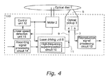
- An optical disc drive apparatus differs from the apparatus according to the first embodiment in additionally including a linear speed detection unit 15 as shown in Fig. 4 .
- the other structure of the optical disc drive apparatus according to the third embodiment of the present invention is identical to the corresponding structure of the apparatus of the first embodiment, and will not be described in detail in the present embodiment.
- the linear speed detection unit 15 detects the linear speed of the spot of the laser beam 5, which illuminates the optical disc 1. More specifically, the linear speed detection unit 15 preferably detects the actual rotation speed of the motor 2, and calculates the linear speed based on the detected rotation speed. Alternatively, the linear speed detection unit 15 may calculate the linear speed based on servo information detected by a servo control circuit (not shown) of the optical pickup 3. More preferably, the control unit 12 controls the laser driving unit 8 based on the linear speed detected by the linear speed detection unit 15. As a result, when the reproduction mode of the optical disc drive apparatus is switched between the normal reproduction mode and the high-speed reproduction mode, the reproduction power of the laser beam 5 is optimized in real time according to the actual rotation speed of the optical disc 1.
- the optical disc drive apparatus of the third embodiment reliably prevents the reproduction erasure from occurring on the optical disc 1, reliably maintains the S/N ratio to be high for the reproduction signal processing circuit 13, and further reliably prevents aliasing noise from being generated in the reproduction signal 7.
- the above embodiments of the present invention describe, as specific examples, their reproduction conditions used when the optical disc 1 is a recordable Blu-ray disc.
- the application of the present invention should not be limited to such reproduction conditions.
- the present invention is applicable to optical disc drive apparatuses that differ from the above optical disc drive apparatuses in, for example, the ratio of the reproduction speed or the reproduction power set in the normal reproduction mode and in the high-speed reproduction mode, or in the relationship between the frequency of the high-frequency current 11 and the frequency of the shortest mark signal, or is also applicable to other typical optical discs.
- the present invention is obviously applicable to an apparatus that reproduces data from a rewritable optical disc.
- the present invention which has the advantageous effects of improving the S/N ratio and preventing EMI (Electro Magnetic Interference) associated with high-frequency superimposition, is applicable even to an optical disc apparatus that sets a high-speed reproduction mode for a read-only optical disc, which has no possibility of the reproduction erasure. In this way, application of the present invention should not be limited.
- the present invention relates to the optical disc drive apparatus and is useful in high-speed reproduction of an optical disc as described above. Therefore, the present invention is obviously industrially applicable.
Landscapes
- Physics & Mathematics (AREA)
- Optics & Photonics (AREA)
- Optical Head (AREA)
- Optical Recording Or Reproduction (AREA)
Applications Claiming Priority (2)
| Application Number | Priority Date | Filing Date | Title |
|---|---|---|---|
| JP2005290692 | 2005-10-04 | ||
| PCT/JP2006/319860 WO2007043406A1 (ja) | 2005-10-04 | 2006-10-04 | 光ディスクドライブ装置、及びそれを用いた光ディスクの再生方法 |
Publications (3)
| Publication Number | Publication Date |
|---|---|
| EP1936611A1 true EP1936611A1 (de) | 2008-06-25 |
| EP1936611A4 EP1936611A4 (de) | 2008-11-26 |
| EP1936611B1 EP1936611B1 (de) | 2009-09-23 |
Family
ID=37942650
Family Applications (1)
| Application Number | Title | Priority Date | Filing Date |
|---|---|---|---|
| EP06811200A Active EP1936611B1 (de) | 2005-10-04 | 2006-10-04 | Optische datenträger-laufwerkeinrichtung und optisches datenträger-wiedergabeverfahren damit |
Country Status (6)
| Country | Link |
|---|---|
| US (1) | US8111599B2 (de) |
| EP (1) | EP1936611B1 (de) |
| JP (1) | JP4759569B2 (de) |
| CN (1) | CN101283408B (de) |
| DE (1) | DE602006009410D1 (de) |
| WO (1) | WO2007043406A1 (de) |
Cited By (2)
| Publication number | Priority date | Publication date | Assignee | Title |
|---|---|---|---|---|
| US8000177B2 (en) | 2006-06-12 | 2011-08-16 | Panasonic Corporation | Reading device and reading method for an optical data recording medium |
| US8279732B2 (en) * | 2008-12-22 | 2012-10-02 | Hitachi-Lg Data Storage, Inc. | Optical disc drive and optical information read method |
Families Citing this family (5)
| Publication number | Priority date | Publication date | Assignee | Title |
|---|---|---|---|---|
| US8068391B2 (en) | 2006-06-20 | 2011-11-29 | Pioneer Corporation | Optical recording/reproducing method, system, and program |
| JP5377499B2 (ja) * | 2008-08-28 | 2013-12-25 | パナソニック株式会社 | 光学的情報再生装置、及び光学的情報再生装置の情報再生方法 |
| JP2011134414A (ja) * | 2009-12-25 | 2011-07-07 | Hitachi-Lg Data Storage Inc | 光ディスク装置及び光ディスク装置におけるデータ再生方法 |
| JP2011134407A (ja) * | 2009-12-25 | 2011-07-07 | Hitachi-Lg Data Storage Inc | 光ディスク装置及びディスク判別方法 |
| JP2014086107A (ja) * | 2012-10-23 | 2014-05-12 | Funai Electric Co Ltd | 光ディスク装置、及び光ディスクの再生方法 |
Family Cites Families (25)
| Publication number | Priority date | Publication date | Assignee | Title |
|---|---|---|---|---|
| US4819242A (en) * | 1985-11-20 | 1989-04-04 | Hitachi, Ltd. | Semiconductor laser driver circuit |
| JP2528821B2 (ja) | 1985-11-20 | 1996-08-28 | 株式会社日立製作所 | 光情報処理装置 |
| JPH0325732A (ja) | 1989-06-23 | 1991-02-04 | Ricoh Co Ltd | 半導体レーザのノイズ低減回路 |
| JPH06259799A (ja) * | 1993-03-04 | 1994-09-16 | Nikon Corp | 光ディスクの再生方法及び再生装置 |
| KR0157665B1 (ko) * | 1993-09-20 | 1998-11-16 | 모리시타 요이찌 | 압축텔레비젼신호기록재생장치 |
| JP3567472B2 (ja) * | 1993-09-29 | 2004-09-22 | ソニー株式会社 | 光磁気記録装置 |
| JP3289045B2 (ja) * | 1994-04-12 | 2002-06-04 | 三菱電機株式会社 | ディジタル記録再生装置 |
| US5572155A (en) * | 1994-06-20 | 1996-11-05 | Fuji Photo Film Co., Ltd. | CCD signal read-out circuit free from ailiasing of high-frequency noises |
| JPH0927154A (ja) * | 1995-07-10 | 1997-01-28 | Fujitsu Ltd | 光磁気ディスク装置 |
| JP3780650B2 (ja) | 1997-08-05 | 2006-05-31 | ソニー株式会社 | 半導体レーザの平均光出力の設定方法および半導体レーザの高周波電流の重畳条件の設定方法 |
| US6013959A (en) * | 1998-06-01 | 2000-01-11 | Eaton Corporation | Lamination structure for an electromagnetic device |
| US6421314B1 (en) * | 1998-09-10 | 2002-07-16 | Sony Corporation | Semiconductor laser drive device, optical head, optical disk device and optical disk recording and reproducing method |
| JP4051590B2 (ja) | 1999-06-30 | 2008-02-27 | ソニー株式会社 | 光情報再生装置及び光情報再生装置の光量設定方法 |
| JP3740413B2 (ja) * | 2001-12-20 | 2006-02-01 | 株式会社日立製作所 | 高周波重畳方法およびこれを用いた光ディスク装置 |
| JP2003289171A (ja) * | 2002-01-23 | 2003-10-10 | Sony Corp | 半導体レーザ駆動回路及びその方法 |
| JP4010884B2 (ja) * | 2002-06-14 | 2007-11-21 | 富士通株式会社 | 光学的記憶装置及び発光制御方法 |
| CN1326132C (zh) * | 2002-10-28 | 2007-07-11 | 松下电器产业株式会社 | 半导体激光驱动装置、光学头装置以及光信息处理装置 |
| CN1306506C (zh) | 2003-05-20 | 2007-03-21 | 松下电器产业株式会社 | 光盘装置以及信息记录再生方法 |
| WO2005043521A1 (ja) * | 2003-10-31 | 2005-05-12 | Pioneer Corporation | 情報記録再生装置、情報記録再生方法および情報記録再生プログラム |
| JP2006221706A (ja) * | 2005-02-09 | 2006-08-24 | Canon Inc | 光学的情報再生装置及び光学的情報再生方法 |
| TW200703325A (en) * | 2005-03-29 | 2007-01-16 | Hitachi Maxell | Method for evaluating optical recording medium, optical recording medium, and information-recording/reproducing apparatus |
| JP2006303332A (ja) * | 2005-04-22 | 2006-11-02 | Ricoh Opt Ind Co Ltd | 光源装置およびそれを用いた光ピックアップ装置、光ビーム走査装置 |
| JP2007004914A (ja) * | 2005-06-24 | 2007-01-11 | Hitachi Ltd | 光ディスク再生装置およびレーザダイオード駆動方法 |
| JP2007073147A (ja) * | 2005-09-08 | 2007-03-22 | Hitachi Ltd | 光ディスク装置及びそれに用いられる集積回路 |
| EP2339578A1 (de) | 2006-06-12 | 2011-06-29 | Panasonic Corporation | Lesevorrichtung und Leseverfahren für ein optisches Datenaufzeichnungsmedium |
-
2006
- 2006-10-04 CN CN2006800370341A patent/CN101283408B/zh not_active Expired - Fee Related
- 2006-10-04 US US12/089,172 patent/US8111599B2/en active Active
- 2006-10-04 WO PCT/JP2006/319860 patent/WO2007043406A1/ja not_active Ceased
- 2006-10-04 DE DE602006009410T patent/DE602006009410D1/de active Active
- 2006-10-04 EP EP06811200A patent/EP1936611B1/de active Active
- 2006-10-04 JP JP2007539890A patent/JP4759569B2/ja active Active
Cited By (2)
| Publication number | Priority date | Publication date | Assignee | Title |
|---|---|---|---|---|
| US8000177B2 (en) | 2006-06-12 | 2011-08-16 | Panasonic Corporation | Reading device and reading method for an optical data recording medium |
| US8279732B2 (en) * | 2008-12-22 | 2012-10-02 | Hitachi-Lg Data Storage, Inc. | Optical disc drive and optical information read method |
Also Published As
| Publication number | Publication date |
|---|---|
| DE602006009410D1 (de) | 2009-11-05 |
| JP4759569B2 (ja) | 2011-08-31 |
| EP1936611B1 (de) | 2009-09-23 |
| JPWO2007043406A1 (ja) | 2009-04-16 |
| CN101283408B (zh) | 2011-01-05 |
| US20100172230A1 (en) | 2010-07-08 |
| EP1936611A4 (de) | 2008-11-26 |
| US8111599B2 (en) | 2012-02-07 |
| WO2007043406A1 (ja) | 2007-04-19 |
| CN101283408A (zh) | 2008-10-08 |
Similar Documents
| Publication | Publication Date | Title |
|---|---|---|
| US6859425B2 (en) | Wobble signal detection circuit and optical disk device | |
| US8111599B2 (en) | Optical disc drive apparatus and optical disc reproduction method using the same | |
| CN1637877A (zh) | 摆频信号提取电路和光盘驱动器 | |
| JP2008262629A (ja) | 光ディスク装置及び再生方法 | |
| US6990056B2 (en) | Optical disk device | |
| US7742371B2 (en) | Information recording/reproducing device, information recording/reproducing method, and information recording/reproducing program | |
| US7738328B2 (en) | Optical disk apparatus for carrying out a defocus regulation | |
| US20040223433A1 (en) | Optical disc playback apparatus, microcomputer, and rotational speed control method for optical disc playback apparatus | |
| JP2002230760A (ja) | 情報記録装置およびプログラム | |
| CN102194477B (zh) | 光盘装置 | |
| CN100349218C (zh) | 光盘记录/再现装置及其用于确定最佳再现速度的方法 | |
| KR100556495B1 (ko) | 광 디스크 기록 재생 방법 및 장치 | |
| US7317667B2 (en) | Wobble signal extraction circuit and optical disk device | |
| US20090262615A1 (en) | Optical disc drive and method of controlling the same | |
| JP2004199779A (ja) | 光ディスク記録再生装置のチルト制御方法 | |
| US20070165511A1 (en) | Signal processing method and optical pickup for keeping available information during high speed optical recording | |
| US7471596B2 (en) | Optical disc reproduction device and tracking control method applied to an optical disc reproduction device | |
| JP2005243137A (ja) | 光ディスク記録再生装置の記録制御方法 | |
| JP2000228013A (ja) | 光学情報の再生方法、記録方法および情報記録媒体 | |
| JP2007172689A (ja) | 光情報記録媒体、情報再生方法及び情報再生装置 | |
| JP2001093149A (ja) | 光ディスク記録再生装置の記録制御方法 | |
| JP2006120289A (ja) | 光ディスク記録再生装置のレーザー出力設定方法 | |
| JP2005251288A (ja) | 光ディスク記録装置の記録制御方法 | |
| JP2003085783A (ja) | 光学式ピックアップ、光学式ディスク記録再生装置、光学式ピックアップ用増幅器 | |
| JP2004071142A (ja) | 光ディスク装置および光ディスク装置における記録制御方法 |
Legal Events
| Date | Code | Title | Description |
|---|---|---|---|
| PUAI | Public reference made under article 153(3) epc to a published international application that has entered the european phase |
Free format text: ORIGINAL CODE: 0009012 |
|
| 17P | Request for examination filed |
Effective date: 20080506 |
|
| AK | Designated contracting states |
Kind code of ref document: A1 Designated state(s): DE FR GB |
|
| RBV | Designated contracting states (corrected) |
Designated state(s): DE FR GB |
|
| RAP1 | Party data changed (applicant data changed or rights of an application transferred) |
Owner name: PANASONIC CORPORATION |
|
| A4 | Supplementary search report drawn up and despatched |
Effective date: 20081029 |
|
| GRAP | Despatch of communication of intention to grant a patent |
Free format text: ORIGINAL CODE: EPIDOSNIGR1 |
|
| DAX | Request for extension of the european patent (deleted) | ||
| GRAS | Grant fee paid |
Free format text: ORIGINAL CODE: EPIDOSNIGR3 |
|
| GRAA | (expected) grant |
Free format text: ORIGINAL CODE: 0009210 |
|
| AK | Designated contracting states |
Kind code of ref document: B1 Designated state(s): DE FR GB |
|
| REG | Reference to a national code |
Ref country code: GB Ref legal event code: FG4D |
|
| REF | Corresponds to: |
Ref document number: 602006009410 Country of ref document: DE Date of ref document: 20091105 Kind code of ref document: P |
|
| PLBE | No opposition filed within time limit |
Free format text: ORIGINAL CODE: 0009261 |
|
| STAA | Information on the status of an ep patent application or granted ep patent |
Free format text: STATUS: NO OPPOSITION FILED WITHIN TIME LIMIT |
|
| 26N | No opposition filed |
Effective date: 20100624 |
|
| REG | Reference to a national code |
Ref country code: FR Ref legal event code: PLFP Year of fee payment: 11 |
|
| REG | Reference to a national code |
Ref country code: FR Ref legal event code: PLFP Year of fee payment: 12 |
|
| REG | Reference to a national code |
Ref country code: FR Ref legal event code: PLFP Year of fee payment: 13 |
|
| PGFP | Annual fee paid to national office [announced via postgrant information from national office to epo] |
Ref country code: GB Payment date: 20250814 Year of fee payment: 20 |
|
| PGFP | Annual fee paid to national office [announced via postgrant information from national office to epo] |
Ref country code: FR Payment date: 20250808 Year of fee payment: 20 |
|
| PGFP | Annual fee paid to national office [announced via postgrant information from national office to epo] |
Ref country code: DE Payment date: 20250813 Year of fee payment: 20 |