EP1936740A1 - Antenne de mesure d'une information de mouvement d'après le principe Doppler, transpondeur, système et procédé - Google Patents
Antenne de mesure d'une information de mouvement d'après le principe Doppler, transpondeur, système et procédé Download PDFInfo
- Publication number
- EP1936740A1 EP1936740A1 EP07024616A EP07024616A EP1936740A1 EP 1936740 A1 EP1936740 A1 EP 1936740A1 EP 07024616 A EP07024616 A EP 07024616A EP 07024616 A EP07024616 A EP 07024616A EP 1936740 A1 EP1936740 A1 EP 1936740A1
- Authority
- EP
- European Patent Office
- Prior art keywords
- antenna
- transponder
- frequency
- transport
- reading
- Prior art date
- Legal status (The legal status is an assumption and is not a legal conclusion. Google has not performed a legal analysis and makes no representation as to the accuracy of the status listed.)
- Granted
Links
Images
Classifications
-
- H—ELECTRICITY
- H01—ELECTRIC ELEMENTS
- H01Q—ANTENNAS, i.e. RADIO AERIALS
- H01Q15/00—Devices for reflection, refraction, diffraction or polarisation of waves radiated from an antenna, e.g. quasi-optical devices
- H01Q15/0006—Devices acting selectively as reflecting surface, as diffracting or as refracting device, e.g. frequency filtering or angular spatial filtering devices
- H01Q15/0013—Devices acting selectively as reflecting surface, as diffracting or as refracting device, e.g. frequency filtering or angular spatial filtering devices said selective devices working as frequency-selective reflecting surfaces, e.g. FSS, dichroic plates, surfaces being partly transmissive and reflective
- H01Q15/002—Devices acting selectively as reflecting surface, as diffracting or as refracting device, e.g. frequency filtering or angular spatial filtering devices said selective devices working as frequency-selective reflecting surfaces, e.g. FSS, dichroic plates, surfaces being partly transmissive and reflective said selective devices being reconfigurable or tunable, e.g. using switches or diodes
-
- G—PHYSICS
- G07—CHECKING-DEVICES
- G07B—TICKET-ISSUING APPARATUS; FARE-REGISTERING APPARATUS; FRANKING APPARATUS
- G07B15/00—Arrangements or apparatus for collecting fares, tolls or entrance fees at one or more control points
- G07B15/02—Arrangements or apparatus for collecting fares, tolls or entrance fees at one or more control points taking into account a variable factor such as distance or time, e.g. for passenger transport, parking systems or car rental systems
-
- H—ELECTRICITY
- H01—ELECTRIC ELEMENTS
- H01Q—ANTENNAS, i.e. RADIO AERIALS
- H01Q1/00—Details of, or arrangements associated with, antennas
- H01Q1/12—Supports; Mounting means
- H01Q1/22—Supports; Mounting means by structural association with other equipment or articles
- H01Q1/2208—Supports; Mounting means by structural association with other equipment or articles associated with components used in interrogation type services, i.e. in systems for information exchange between an interrogator/reader and a tag/transponder, e.g. in Radio Frequency Identification [RFID] systems
- H01Q1/2225—Supports; Mounting means by structural association with other equipment or articles associated with components used in interrogation type services, i.e. in systems for information exchange between an interrogator/reader and a tag/transponder, e.g. in Radio Frequency Identification [RFID] systems used in active tags, i.e. provided with its own power source or in passive tags, i.e. deriving power from RF signal
Definitions
- the invention relates to an antenna for measuring a movement information, in particular speed or distance, according to the Doppler principle, a transponder with such an antenna, a system with transponders and a reading antenna and a corresponding method.
- a transponder has an antenna and a chip which can be coupled or coupled to the antenna and which are arranged on a carrier.
- An exemplary microwave transponder according to the prior art is in Fig.1 shown.
- the chip stores data which are contactlessly accessible via the antenna using a suitable reading device.
- Transponders are used for example in the so-called ticketing area as electronic tickets, for example in public transport.
- Each passenger liable to pay carries a transponder in the use of affected means of public transport, in which data is stored, which allow a calculation of the fare to be paid for the use.
- a credit can be stored in the chip, which is used directly for the payment of the fare.
- transponder detection readers are located at entrances to restricted access areas in the vicinity of the means of transport, such as platforms and / or at doors of transportation, and require that one or both of them passengers alighting, hold their transponder directly to the reader and thereby register their entry or exit.
- a system which registers passengers entering and / or exiting, is also referred to as a check-in / check-out system.
- long-range transponders are used for ticketing in so-called long-range systems, with a range of 1 m to typically 10 m, which operate at a resonant frequency in the microwave range of 2.45 GHz, 915 MHz or 868 MHz.
- Transponders in long-range systems also include transponders with a resonant frequency of 5.8 GHz or 24.125 GHz.
- an incoming or outgoing passenger does not have to actively hold his transponder to a reader, but the transponder carried in the pocket, for example, is detected automatically as soon as the passenger gets into the transmission range of the reader.
- a reading device is mounted on doors to a means of transport, which wakes up and registers the transponder from an idle state.
- a monitoring reader is mounted which continuously monitors the presence of registered transponders at short intervals. A fare is determined from the presence of the transponder within the means of transport or from the distance traveled during the journey.
- Such a system in which the presence of passengers is registered, is also referred to as Be-in / Be-out system.
- An example of a Be-in / Be-out system is the Dresden pilot project ALLFA (see for example http://efa.vvo-online.de/allfa/index.html).
- Transponders are still used, for example, in warehousing.
- a transponder is mounted on each stored goods or containers for storage of goods, in which specific for the goods Data are stored.
- a reader To read out the data from transponders, a reader must reach the range of the transponder.
- a Doppler radar speedometer for the microwave range is, for example, in DE 3219 819 C2 described.
- a Doppler radar sensor is attached to a moving body and emits microwaves that are reflected from the (stationary) ground. Parts of the emitted and reflected microwaves are mixed, thereby generating Doppler signals from which the velocity of the moving body is derived.
- US 5,680,459 describes an electronic identification system for an automatic fare collection with multiple transponders, in which the simultaneous identification of multiple transponders is made possible by the fact that the individual transponders are read in different time windows.
- a measurement of a movement information, in particular speed or distance, according to the Doppler principle would also be desirable, for example in ticketing or in storage. This would allow long-range measurements without the need to hold the transponder directly to a reader, thus making the capture of transponders comfortable.
- the Doppler frequency can be increased in other applications, for example in vehicle detection.
- the speed of movement during vehicle detection is usually high, so that the Doppler effect is easily measurable.
- the transmission frequency of the transponder transponders used is defined by standards such as ISO 18000-6 or ISO 18000-4 and must be in the microwave range of approximately 800 MHz to approximately 6 GHz.
- the speeds of movement v in, for example, ticketing and storage are generally low, for example of the order of magnitude of 1 m / s or even less.
- Direct transmission of a known for example for vehicle detection system speed detection by Doppler effect on areas such as ticketing or storage, with low frequencies and movement speeds, is therefore not possible because the Doppler frequency would be too low a frequency.
- Frequency-selective surfaces are periodic conductive structures on surfaces which have filter properties relative to electromagnetic waves. Depending on the geometric dimensioning of the structures, low-pass, high-pass, band-pass or band-stop filter properties can thus be realized with respect to an incident electromagnetic wave.
- z. B. building structures such as Radar domes, which should be uninterrupted for the radar frequency range, window covers for microwave ovens, which are to achieve a particularly high attenuation in the microwave frequency range, or even wallpapers that lock specific frequency ranges (eg Bluetooth), but adjacent frequency ranges pass unhindered (z B. mobile communications).
- Frequency-selective layers are used in the micro- and millimeter wave range for the effective use of reflector antennas, as filters and artificial dielectrics, as a mirror to increase the pumping efficiency of lasers and as polarizers, beam splitters or filters and in the optical field to increase the efficiency of solar panels.
- aperture geometries If there are conductive areas on a nonconductive surface, we speak of patch geometries, if there are nonconductive areas on a conductive surface, this is referred to as aperture geometries.
- an electromagnetic wave When an electromagnetic wave hits an FSS, it generates electrical currents on the conductive areas of the FSS. As a result, a part of the wave can be reflected when hitting the layer.
- the complex amplitudes of the reflected or transmitted components, based on the amplitude of the incident wave, are referred to as reflection or transmission coefficients.
- the so-called backscatter cross section of the FSS for the incident wave indicates what proportion of the incident wave is reflected at the FSS. If the wavelength of a wave incident on an FSS is of the same order of magnitude as the dimensions of the elementary cell (individual regions) of the FSS, strong resonances occur as the frequency of the incident wave changes.
- the backscatter cross section of FSS for the incident wave has a maximum at the FSS in patch geometry at the resonant frequency.
- the incident wave is substantially completely transmitted at the resonant frequency.
- the backscatter cross section of the FSS for the incident wave has a minimum at FSS in aperture geometry at the resonant frequency.
- WO 2006/027112 A1 describes the use of a frequency-selective surface as an authenticity feature for eg banknotes or chip cards.
- the invention is based on the object to enable measurements of motion information, in particular speed or distance, according to the Doppler principle also for systems with transponders whose Doppler frequency is hardly or not measurable without further precautions.
- the antenna according to the invention according to claim 1 is for measuring a movement information, in particular speed or distance, after provided the Doppler principle and has an antenna surface made of a conductive material.
- the antenna has a predetermined antenna structure by which a first resonance frequency of the antenna is set.
- the antenna is characterized in that the antenna surface is provided with a frequency-selective surface (FSS), by which a second resonance frequency of the antenna is set, which is different from the first resonance frequency.
- FSS frequency-selective surface
- the second resonant frequency results in a second Doppler frequency which is also at a different frequency than the Doppler frequency due to the first resonant frequency, assuming the same relative velocity between the antenna and a reader antenna of a reader.
- the second resonant frequency is at a higher frequency than the first resonant frequency.
- This alternative of the invention is particularly preferred for applications such as ticketing, warehousing, animal monitoring and the like, since relatively low first resonance frequencies are enshrined in standards and, on the other hand, the relative movements of the antenna and reader antenna of a reader are low.
- the frequency-selective surface consists of a periodically structured conductive structure.
- the frequency-selective surface is designed in aperture geometry, wherein the electrically conductive antenna surface is provided with a periodic arrangement of apertures.
- the apertures may be designed as openings in the electrically conductive antenna surface and may optionally be filled with a dielectric.
- the frequency-selective surface is designed in patch geometry, the antenna surface being provided with a periodic array of electrically conductive elements which are electrically isolated from the antenna surface, e.g. through a dielectric interlayer.
- the antenna with the frequency-selective surface further comprises an adjusting device with which a backscatter cross section of the frequency-selective surface in a frequency range encompassing at least the second resonant frequency can be changed.
- the adjusting device may have one or more load resistors, for example, in the case of a frequency-selective surface in patch geometry, which can be selectively coupled to or decoupled from the conductive elements.
- the backscatter cross section of the antenna is different due to the frequency-selective surface.
- the frequency-selective surface can optionally be switched on and off in relation to a reading antenna of a reading device which emits electromagnetic waves at a fixed frequency, in particular the second resonance frequency.
- the first resonant frequency is optionally in the microwave range, in particular in the frequency range from about 800 MHz to about 6 GHz, in particular at a frequency of 868 MHz or 915 MHz or 2.45 GHz, optionally at a frequency fixed by a standard.
- the transponder according to the invention is equipped with an antenna according to the invention according to one of the embodiments and variants described above and with a chip electrically coupled or coupleable to the antenna.
- the antenna and the chip are arranged on an arbitrarily designed carrier.
- the transponder is designed as a label, (contactless) chip card, voluminous transponder or transponder of other design.
- the transponder according to the invention can optionally be used as an electronic ticket, in particular for paid transport, or optionally in warehousing, or optionally in baggage handling in travel, in particular air traffic, ferry and / or rail traffic, or in animal surveillance or other applications, especially in other applications where the use of RFID tags is known.
- the system according to the invention for managing the use of at least one paid means of transport by passengers comprises: for each pay passenger at least one transponder, each paying passenger using the means of transport being obliged to carry the transponder during use of the means of transport; at least one reading antenna mounted on an access to the means of transport and arranged to communicate with the transponder at the second resonance frequency and with which movement information, In particular, speed or distance of a transponder relative to the reading antenna according to the Doppler principle at the second resonant frequency is measurable, such that between a transponder-equipped passenger who enters or leaves the means of transport or surrounding the transport restricted access area is distinguishable.
- the reader antenna is optionally configured to communicate with the antenna, but not to communicate with the chip.
- communication with the chip is possible at the first resonant frequency, optionally with a suitable reader other than the reader antenna.
- the system according to the invention is thus a ticketting system. It is particularly applicable for public transport.
- the system according to the invention is particularly convenient compared to known ticketing systems. Since in the system according to the invention the detection of the transponder takes place according to the Doppler principle, a very long-range measurement is possible. Consequently, it is possible to detect the boarding and disembarking of passengers without having to hold their transponder used as a ticket to a reader, which is an advantage over conventional check-in / check-out systems. On the other hand, within the vehicle no surveillance antenna need be provided to monitor the presence of detected passengers throughout the ride, which is an advantage over conventional long-range loading / unloading systems.
- the second resonant frequency is used to measure movement information according to the Doppler principle, in particular to passengers getting in or out to capture.
- communication with the chip of the transponder is preferably carried out at the first resonant frequency, which is defined, for example, by a standard such as ISO 18000-6 or ISO 18000-4, optionally according to any communication method according to the prior art.
- a door or doorway or doorway or the like of a vehicle may be provided as access to the vehicle.
- a vehicle e.g., bus, subway train, railway car, tramcar, etc.
- access to a platform may be provided as access to an access restricted area.
- a reader antenna is optionally arranged at each passenger access access to a means of transportation or to the restricted access area.
- the reading antenna for Doppler measurement has a spatial directional characteristic such that the transponder is oriented in an inward direction the means of transport or the restricted access area with the reading antenna is more or less detectable than in an outside direction out of the means of transport or the restricted access area.
- a reading antenna on a doorway of a vehicle has a directional characteristic directed toward the exterior of the vehicle. An ascending passenger is thus detected as a transponder to be moved to the reading antenna until the passenger passes through the doorway.
- the system further optionally has a reading device attached to an access to the means of transport, which is set up for communication with the transponder, in particular with the chip of the transponder, at the first resonance frequency.
- the reading device is, for example, in particular configured to write fare information about a fare to be paid by the passenger into the chip of the transponder or to read it from the chip.
- a transponder is woken up at the "fundamental frequency" of the transponder (first resonance frequency) and then the Doppler measurement is carried out on the alert transponder at the "FSS frequency” (second resonance frequency).
- FSS frequency second resonance frequency
- a single transponder activated at a time. In this way, collisions are avoided by a simultaneous communication with the plurality of transponders.
- At least one, optionally exactly one, arbitrary individual transponder is activated by the reading device for the first resonance frequency by means of the setting device and a measurement on the activated individual transponder a movement information according to the Doppler principle at the second resonant frequency performed.
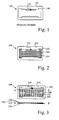
- Fig.1 shows a transponder 100 with a chip 110 and an antenna 120, which are arranged on a carrier 130, according to the prior art.
- the transponder 100 is designed here by way of example as a chip card in the format ID-1 according to ISO 7810.
- the antenna 120 has a first resonance frequency at 868 MHz due to its design and its geometric dimensions. For this frequency, the in Fig.1 exemplified planar antenna design, in which the antenna 120 has a planar antenna surface.
- FIG. 12 shows a transponder 200 having a chip 210 and an antenna 220 on a carrier 230, wherein the antenna 220 is provided with an FSS 240 in aperture geometry, according to a first embodiment of the invention.
- the transponder 200 out Fig. 2 at the antenna surface of the antenna 220, a plurality of periodically arranged apertures (apertures) 250 which in their entirety constitute the frequency selective surface FSS 240.
- the antenna 220 has a first resonant frequency at 868 MHz due to its design and geometrical dimensions. Due to the FSS 240, the antenna 220 has a second resonant frequency at a frequency of over 10 GHz, typically about 70 ...
- Fig. 3 1 shows a transponder 300 with a chip 310 and an antenna 320 with a FSS 340 in patch geometry, arranged on a carrier 330, according to a second embodiment of the invention.
- the transponder 300 off Fig. 3 has the transponder 300 off Fig. 3 on the antenna surface of the antenna 320, a plurality of periodically arranged conductive elements 350, which in their entirety form the frequency-selective surface FSS 340.
- an electrically insulating intermediate layer 360 Arranged between the antenna surface of the antenna 320 and the conductive elements 350 of the FSS 340 is an electrically insulating intermediate layer 360, with which the antenna 320 and the conductive elements 350 of the FSS 340 are electrically isolated from each other.
- the intermediate layer 360 is formed from a dielectric, for example from a plastic, for example from a plastic film.
- the individual conductive elements 350 are electrically connected to each other.
- the interconnected conductive elements 350 are electrically coupled or coupled to the chip 310, eg via one or more supply lines and logic lines.
- To the conductive elements 350 is further a - preferably variable - load resistor (not shown separately) can be coupled.
- the layer structure of the transponder 300 with the carrier 330, which on the carrier 330 arranged in the antenna 320, the insulating intermediate layer 360 disposed on the antenna 320 and the electrically conductive elements 350 disposed on the intermediate layer 360 is in the lower part of Fig. 3 in a sectional view along the line AB in the upper part of Fig. 3 illustrated.
- the antenna 320 has a first resonant frequency at 868 MHz due to its design and geometric dimensions. Due to the FSS 340, the antenna 320 has a second resonant frequency at a frequency of approximately well over 10 GHz, eg 70 ... 150 (200) ... GHz.
- the conductive elements 350 of the transponder 300 Fig. 3 are designed as rectangular areas.
- the elements 350 may have any other suitable shape.
- the apertures 250 of the transponder 200 can be made Fig. 2 have any suitable shape.
- a suitably dimensioned load resistor is coupled to the conductive elements 350.
- the signal for coupling the load resistor is transmitted to the chip 310 at the first resonant frequency with a suitable suitable reader.
- the chip 310 causes the coupling of the load resistor.
- the backscatter cross-section of the frequency-selective surface 340 which is low without the load resistor, is increased to a maximum value.
- the transponder 300 is activated and the Doppler measurement at the second resonance frequency can be performed.
Landscapes
- Business, Economics & Management (AREA)
- Finance (AREA)
- Physics & Mathematics (AREA)
- General Physics & Mathematics (AREA)
- Radar Systems Or Details Thereof (AREA)
Applications Claiming Priority (1)
| Application Number | Priority Date | Filing Date | Title |
|---|---|---|---|
| DE200610061312 DE102006061312A1 (de) | 2006-12-22 | 2006-12-22 | Antenne zur Messung einer Bewegungsinformation nach dem Doppler-Prinzip, Transponder, System und Verfahren |
Publications (2)
| Publication Number | Publication Date |
|---|---|
| EP1936740A1 true EP1936740A1 (fr) | 2008-06-25 |
| EP1936740B1 EP1936740B1 (fr) | 2015-09-16 |
Family
ID=39156228
Family Applications (1)
| Application Number | Title | Priority Date | Filing Date |
|---|---|---|---|
| EP07024616.0A Active EP1936740B1 (fr) | 2006-12-22 | 2007-12-19 | Système et procédé de mesure d'une information de mouvement d'après le principe Doppler |
Country Status (2)
| Country | Link |
|---|---|
| EP (1) | EP1936740B1 (fr) |
| DE (1) | DE102006061312A1 (fr) |
Cited By (1)
| Publication number | Priority date | Publication date | Assignee | Title |
|---|---|---|---|---|
| EP2492848A1 (fr) | 2011-02-24 | 2012-08-29 | Giesecke & Devrient GmbH | Procédé de fonctionnement d'un support de données et support à données doté d'une structure d'antennes |
Families Citing this family (1)
| Publication number | Priority date | Publication date | Assignee | Title |
|---|---|---|---|---|
| EP4376220A3 (fr) * | 2020-02-04 | 2024-07-31 | Aptiv Technologies AG | Dispositif radar |
Citations (9)
| Publication number | Priority date | Publication date | Assignee | Title |
|---|---|---|---|---|
| DE3219819C2 (de) | 1981-05-27 | 1984-12-13 | Hitachi, Ltd., Tokio/Tokyo | Doppler-Radar-Geschwindigkeitsmesser |
| WO1992016031A1 (fr) * | 1991-02-27 | 1992-09-17 | Alenia-Aeritalia & Selenia S.P.A. | Structure dichroïque a selection de frequences possedant une bande passante variable et applications |
| WO1993023833A1 (fr) * | 1992-05-11 | 1993-11-25 | Saab-Scania Combitech Aktiebolag | Dispositif de detection et de transfert d'information |
| US5680459A (en) | 1994-04-29 | 1997-10-21 | Kasten Chase Applied Research Limited | Passive transponder |
| DE19652324A1 (de) * | 1996-12-16 | 1998-06-25 | Siemens Ag | Transponder mit einer Mikrowellen-Empfangsantenne |
| EP0853245A2 (fr) * | 1996-12-30 | 1998-07-15 | Lucent Technologies Inc. | Système de détection à rétrodiffusion modulé |
| WO2002039379A1 (fr) * | 2000-11-13 | 2002-05-16 | Infineon Technologies Ag | Support de donnees sans contact |
| WO2002073234A1 (fr) * | 2001-03-14 | 2002-09-19 | Ip And Innovation Company Holdings (Proprietary) Limited | Detection de presence |
| WO2006027112A1 (fr) | 2004-09-06 | 2006-03-16 | Giesecke & Devrient Gmbh | Element de securite comprenant une caracteristique d'authenticite lisible par machine |
Family Cites Families (5)
| Publication number | Priority date | Publication date | Assignee | Title |
|---|---|---|---|---|
| US5512901A (en) * | 1991-09-30 | 1996-04-30 | Trw Inc. | Built-in radiation structure for a millimeter wave radar sensor |
| US5471224A (en) * | 1993-11-12 | 1995-11-28 | Space Systems/Loral Inc. | Frequency selective surface with repeating pattern of concentric closed conductor paths, and antenna having the surface |
| GB2328319B (en) * | 1994-06-22 | 1999-06-02 | British Aerospace | A frequency selective surface |
| US5917458A (en) * | 1995-09-08 | 1999-06-29 | The United States Of America As Represented By The Secretary Of The Navy | Frequency selective surface integrated antenna system |
| US7190325B2 (en) * | 2004-02-18 | 2007-03-13 | Delphi Technologies, Inc. | Dynamic frequency selective surfaces |
-
2006
- 2006-12-22 DE DE200610061312 patent/DE102006061312A1/de not_active Withdrawn
-
2007
- 2007-12-19 EP EP07024616.0A patent/EP1936740B1/fr active Active
Patent Citations (10)
| Publication number | Priority date | Publication date | Assignee | Title |
|---|---|---|---|---|
| DE3219819C2 (de) | 1981-05-27 | 1984-12-13 | Hitachi, Ltd., Tokio/Tokyo | Doppler-Radar-Geschwindigkeitsmesser |
| WO1992016031A1 (fr) * | 1991-02-27 | 1992-09-17 | Alenia-Aeritalia & Selenia S.P.A. | Structure dichroïque a selection de frequences possedant une bande passante variable et applications |
| WO1993023833A1 (fr) * | 1992-05-11 | 1993-11-25 | Saab-Scania Combitech Aktiebolag | Dispositif de detection et de transfert d'information |
| US5680459A (en) | 1994-04-29 | 1997-10-21 | Kasten Chase Applied Research Limited | Passive transponder |
| DE19652324A1 (de) * | 1996-12-16 | 1998-06-25 | Siemens Ag | Transponder mit einer Mikrowellen-Empfangsantenne |
| EP0853245A2 (fr) * | 1996-12-30 | 1998-07-15 | Lucent Technologies Inc. | Système de détection à rétrodiffusion modulé |
| WO2002039379A1 (fr) * | 2000-11-13 | 2002-05-16 | Infineon Technologies Ag | Support de donnees sans contact |
| DE10056148A1 (de) | 2000-11-13 | 2002-05-23 | Infineon Technologies Ag | Kontaktloser Datenträger |
| WO2002073234A1 (fr) * | 2001-03-14 | 2002-09-19 | Ip And Innovation Company Holdings (Proprietary) Limited | Detection de presence |
| WO2006027112A1 (fr) | 2004-09-06 | 2006-03-16 | Giesecke & Devrient Gmbh | Element de securite comprenant une caracteristique d'authenticite lisible par machine |
Non-Patent Citations (2)
| Title |
|---|
| KLAUS FINKENZELLER: "RFID-Handbuch", 1998, CARL HANSER VERLAG, MÜNCHEN, ISBN: 3-446-19376-6, XP002473544 * |
| KLAUS FINKENZELLER: "RFID-Handbuch", 2000, CARL HANSER VERLAG |
Cited By (2)
| Publication number | Priority date | Publication date | Assignee | Title |
|---|---|---|---|---|
| EP2492848A1 (fr) | 2011-02-24 | 2012-08-29 | Giesecke & Devrient GmbH | Procédé de fonctionnement d'un support de données et support à données doté d'une structure d'antennes |
| DE102011012230A1 (de) | 2011-02-24 | 2012-08-30 | Giesecke & Devrient Gmbh | Verfahren zum Betreiben eines Datenträgers und Datenträger mit einer Antennenstruktur |
Also Published As
| Publication number | Publication date |
|---|---|
| DE102006061312A1 (de) | 2008-06-26 |
| EP1936740B1 (fr) | 2015-09-16 |
Similar Documents
| Publication | Publication Date | Title |
|---|---|---|
| DE69332432T2 (de) | Gerät zur identification von beweglichen objekten | |
| EP2205990B1 (fr) | Dispositif de détection d'un véhicule sur une piste d'aéroport | |
| EP0968441B1 (fr) | Procede de traitement de signaux radar | |
| EP2012253B1 (fr) | Lecture d'informations à l'aide d'un capteur optoélectronique et d'un lecteur RFID | |
| EP3131065A1 (fr) | Procede et systeme de controle d'acces | |
| EP2125449B1 (fr) | Procédé de caractérisation de distance pour des systèmes d'accès à couplage inductif pour véhicules | |
| DE102016216251B4 (de) | Kraftfahrzeug zur Nutzung im Straßenverkehr und Verfahren zur Ermittlung einer Ausdehnung eines Fremdfahrzeugs in einem Kraftfahrzeug | |
| CH695907A5 (de) | Zugangskontrolleinrichtung. | |
| EP1274909A1 (fr) | Systeme pour controler l'autorisation d'acces a un vehicule | |
| EP1701287B1 (fr) | Système d'identification et procédé de détection d'informations de mouvement | |
| DE102011014855A1 (de) | Verfahren und Vorrichtung zum Erfassen und Klassifizieren von fahrenden Fahrzeugen | |
| EP3261060B1 (fr) | Procédés de contrôle d'accès dans un système de contrôle d'accès pour personnes ou véhicules automobiles et système de contrôle d'accès | |
| DE102007058278A1 (de) | Sicherheitsgurtsystem | |
| DE102010007415A1 (de) | Radarsignal-Verarbeitungsverfahren | |
| EP2529981B1 (fr) | Procédé et agencement destinés à la reconnaissance d'occupation d'une place assise | |
| EP1936740B1 (fr) | Système et procédé de mesure d'une information de mouvement d'après le principe Doppler | |
| AT4044U1 (de) | Zugangskontrollsystem | |
| DE102022203515B4 (de) | Fahrzeug mit einem Leuchtelement zur Beleuchtung eines Fahrzeugumfelds | |
| EP1860597B1 (fr) | Unité de transfert pour un système d'identification inductif et système d'identification inductif | |
| EP1672560B1 (fr) | Système d'identification à couplage inductif | |
| EP3640896A1 (fr) | Poignée de porte de véhicule pourvue d'électronique de communication de champ proche | |
| DE102007058277A1 (de) | Fahrzeuginsassen-Schutzvorrichtung | |
| DE3636414A1 (de) | Kontrollsystem zur identifizierung von personen und objekten | |
| EP2306406B1 (fr) | Dispositif de contrôle d'accès en construction compacte | |
| EP2592584A1 (fr) | Transaction sans fil sécurisée |
Legal Events
| Date | Code | Title | Description |
|---|---|---|---|
| PUAI | Public reference made under article 153(3) epc to a published international application that has entered the european phase |
Free format text: ORIGINAL CODE: 0009012 |
|
| AK | Designated contracting states |
Kind code of ref document: A1 Designated state(s): AT BE BG CH CY CZ DE DK EE ES FI FR GB GR HU IE IS IT LI LT LU LV MC MT NL PL PT RO SE SI SK TR |
|
| AX | Request for extension of the european patent |
Extension state: AL BA HR MK RS |
|
| 17P | Request for examination filed |
Effective date: 20081229 |
|
| AKX | Designation fees paid |
Designated state(s): AT BE BG CH CY CZ DE DK EE ES FI FR GB GR HU IE IS IT LI LT LU LV MC MT NL PL PT RO SE SI SK TR |
|
| 17Q | First examination report despatched |
Effective date: 20090209 |
|
| GRAP | Despatch of communication of intention to grant a patent |
Free format text: ORIGINAL CODE: EPIDOSNIGR1 |
|
| INTG | Intention to grant announced |
Effective date: 20150417 |
|
| GRAS | Grant fee paid |
Free format text: ORIGINAL CODE: EPIDOSNIGR3 |
|
| GRAA | (expected) grant |
Free format text: ORIGINAL CODE: 0009210 |
|
| AK | Designated contracting states |
Kind code of ref document: B1 Designated state(s): AT BE BG CH CY CZ DE DK EE ES FI FR GB GR HU IE IS IT LI LT LU LV MC MT NL PL PT RO SE SI SK TR |
|
| REG | Reference to a national code |
Ref country code: GB Ref legal event code: FG4D Free format text: NOT ENGLISH |
|
| REG | Reference to a national code |
Ref country code: CH Ref legal event code: EP |
|
| REG | Reference to a national code |
Ref country code: IE Ref legal event code: FG4D Free format text: LANGUAGE OF EP DOCUMENT: GERMAN |
|
| REG | Reference to a national code |
Ref country code: AT Ref legal event code: REF Ref document number: 750449 Country of ref document: AT Kind code of ref document: T Effective date: 20151015 |
|
| REG | Reference to a national code |
Ref country code: DE Ref legal event code: R096 Ref document number: 502007014223 Country of ref document: DE |
|
| REG | Reference to a national code |
Ref country code: CH Ref legal event code: NV Representative=s name: PATENTANWAELTE SCHAAD, BALASS, MENZL AND PARTN, CH |
|
| REG | Reference to a national code |
Ref country code: FR Ref legal event code: PLFP Year of fee payment: 9 |
|
| REG | Reference to a national code |
Ref country code: NL Ref legal event code: MP Effective date: 20150916 |
|
| PG25 | Lapsed in a contracting state [announced via postgrant information from national office to epo] |
Ref country code: LT Free format text: LAPSE BECAUSE OF FAILURE TO SUBMIT A TRANSLATION OF THE DESCRIPTION OR TO PAY THE FEE WITHIN THE PRESCRIBED TIME-LIMIT Effective date: 20150916 Ref country code: FI Free format text: LAPSE BECAUSE OF FAILURE TO SUBMIT A TRANSLATION OF THE DESCRIPTION OR TO PAY THE FEE WITHIN THE PRESCRIBED TIME-LIMIT Effective date: 20150916 Ref country code: GR Free format text: LAPSE BECAUSE OF FAILURE TO SUBMIT A TRANSLATION OF THE DESCRIPTION OR TO PAY THE FEE WITHIN THE PRESCRIBED TIME-LIMIT Effective date: 20151217 Ref country code: LV Free format text: LAPSE BECAUSE OF FAILURE TO SUBMIT A TRANSLATION OF THE DESCRIPTION OR TO PAY THE FEE WITHIN THE PRESCRIBED TIME-LIMIT Effective date: 20150916 |
|
| REG | Reference to a national code |
Ref country code: LT Ref legal event code: MG4D |
|
| PG25 | Lapsed in a contracting state [announced via postgrant information from national office to epo] |
Ref country code: SE Free format text: LAPSE BECAUSE OF FAILURE TO SUBMIT A TRANSLATION OF THE DESCRIPTION OR TO PAY THE FEE WITHIN THE PRESCRIBED TIME-LIMIT Effective date: 20150916 |
|
| PG25 | Lapsed in a contracting state [announced via postgrant information from national office to epo] |
Ref country code: NL Free format text: LAPSE BECAUSE OF FAILURE TO SUBMIT A TRANSLATION OF THE DESCRIPTION OR TO PAY THE FEE WITHIN THE PRESCRIBED TIME-LIMIT Effective date: 20150916 |
|
| PG25 | Lapsed in a contracting state [announced via postgrant information from national office to epo] |
Ref country code: CZ Free format text: LAPSE BECAUSE OF FAILURE TO SUBMIT A TRANSLATION OF THE DESCRIPTION OR TO PAY THE FEE WITHIN THE PRESCRIBED TIME-LIMIT Effective date: 20150916 Ref country code: SK Free format text: LAPSE BECAUSE OF FAILURE TO SUBMIT A TRANSLATION OF THE DESCRIPTION OR TO PAY THE FEE WITHIN THE PRESCRIBED TIME-LIMIT Effective date: 20150916 Ref country code: ES Free format text: LAPSE BECAUSE OF FAILURE TO SUBMIT A TRANSLATION OF THE DESCRIPTION OR TO PAY THE FEE WITHIN THE PRESCRIBED TIME-LIMIT Effective date: 20150916 Ref country code: EE Free format text: LAPSE BECAUSE OF FAILURE TO SUBMIT A TRANSLATION OF THE DESCRIPTION OR TO PAY THE FEE WITHIN THE PRESCRIBED TIME-LIMIT Effective date: 20150916 Ref country code: IT Free format text: LAPSE BECAUSE OF FAILURE TO SUBMIT A TRANSLATION OF THE DESCRIPTION OR TO PAY THE FEE WITHIN THE PRESCRIBED TIME-LIMIT Effective date: 20150916 Ref country code: IS Free format text: LAPSE BECAUSE OF FAILURE TO SUBMIT A TRANSLATION OF THE DESCRIPTION OR TO PAY THE FEE WITHIN THE PRESCRIBED TIME-LIMIT Effective date: 20160116 |
|
| PG25 | Lapsed in a contracting state [announced via postgrant information from national office to epo] |
Ref country code: PT Free format text: LAPSE BECAUSE OF FAILURE TO SUBMIT A TRANSLATION OF THE DESCRIPTION OR TO PAY THE FEE WITHIN THE PRESCRIBED TIME-LIMIT Effective date: 20160118 Ref country code: RO Free format text: LAPSE BECAUSE OF FAILURE TO SUBMIT A TRANSLATION OF THE DESCRIPTION OR TO PAY THE FEE WITHIN THE PRESCRIBED TIME-LIMIT Effective date: 20150916 Ref country code: BE Free format text: LAPSE BECAUSE OF NON-PAYMENT OF DUE FEES Effective date: 20151231 Ref country code: PL Free format text: LAPSE BECAUSE OF FAILURE TO SUBMIT A TRANSLATION OF THE DESCRIPTION OR TO PAY THE FEE WITHIN THE PRESCRIBED TIME-LIMIT Effective date: 20150916 |
|
| REG | Reference to a national code |
Ref country code: DE Ref legal event code: R097 Ref document number: 502007014223 Country of ref document: DE |
|
| PLBE | No opposition filed within time limit |
Free format text: ORIGINAL CODE: 0009261 |
|
| STAA | Information on the status of an ep patent application or granted ep patent |
Free format text: STATUS: NO OPPOSITION FILED WITHIN TIME LIMIT |
|
| PG25 | Lapsed in a contracting state [announced via postgrant information from national office to epo] |
Ref country code: MC Free format text: LAPSE BECAUSE OF FAILURE TO SUBMIT A TRANSLATION OF THE DESCRIPTION OR TO PAY THE FEE WITHIN THE PRESCRIBED TIME-LIMIT Effective date: 20150916 Ref country code: LU Free format text: LAPSE BECAUSE OF FAILURE TO SUBMIT A TRANSLATION OF THE DESCRIPTION OR TO PAY THE FEE WITHIN THE PRESCRIBED TIME-LIMIT Effective date: 20151219 |
|
| 26N | No opposition filed |
Effective date: 20160617 |
|
| PG25 | Lapsed in a contracting state [announced via postgrant information from national office to epo] |
Ref country code: DK Free format text: LAPSE BECAUSE OF FAILURE TO SUBMIT A TRANSLATION OF THE DESCRIPTION OR TO PAY THE FEE WITHIN THE PRESCRIBED TIME-LIMIT Effective date: 20150916 |
|
| REG | Reference to a national code |
Ref country code: IE Ref legal event code: MM4A |
|
| PG25 | Lapsed in a contracting state [announced via postgrant information from national office to epo] |
Ref country code: IE Free format text: LAPSE BECAUSE OF NON-PAYMENT OF DUE FEES Effective date: 20151219 |
|
| PG25 | Lapsed in a contracting state [announced via postgrant information from national office to epo] |
Ref country code: SI Free format text: LAPSE BECAUSE OF FAILURE TO SUBMIT A TRANSLATION OF THE DESCRIPTION OR TO PAY THE FEE WITHIN THE PRESCRIBED TIME-LIMIT Effective date: 20150916 |
|
| REG | Reference to a national code |
Ref country code: FR Ref legal event code: PLFP Year of fee payment: 10 |
|
| REG | Reference to a national code |
Ref country code: AT Ref legal event code: MM01 Ref document number: 750449 Country of ref document: AT Kind code of ref document: T Effective date: 20151219 |
|
| PG25 | Lapsed in a contracting state [announced via postgrant information from national office to epo] |
Ref country code: BG Free format text: LAPSE BECAUSE OF FAILURE TO SUBMIT A TRANSLATION OF THE DESCRIPTION OR TO PAY THE FEE WITHIN THE PRESCRIBED TIME-LIMIT Effective date: 20150916 Ref country code: HU Free format text: LAPSE BECAUSE OF FAILURE TO SUBMIT A TRANSLATION OF THE DESCRIPTION OR TO PAY THE FEE WITHIN THE PRESCRIBED TIME-LIMIT; INVALID AB INITIO Effective date: 20071219 Ref country code: AT Free format text: LAPSE BECAUSE OF NON-PAYMENT OF DUE FEES Effective date: 20151219 |
|
| PG25 | Lapsed in a contracting state [announced via postgrant information from national office to epo] |
Ref country code: CY Free format text: LAPSE BECAUSE OF FAILURE TO SUBMIT A TRANSLATION OF THE DESCRIPTION OR TO PAY THE FEE WITHIN THE PRESCRIBED TIME-LIMIT Effective date: 20150916 |
|
| REG | Reference to a national code |
Ref country code: DE Ref legal event code: R081 Ref document number: 502007014223 Country of ref document: DE Owner name: GIESECKE+DEVRIENT MOBILE SECURITY GMBH, DE Free format text: FORMER OWNER: GIESECKE & DEVRIENT GMBH, 81677 MUENCHEN, DE |
|
| PG25 | Lapsed in a contracting state [announced via postgrant information from national office to epo] |
Ref country code: MT Free format text: LAPSE BECAUSE OF FAILURE TO SUBMIT A TRANSLATION OF THE DESCRIPTION OR TO PAY THE FEE WITHIN THE PRESCRIBED TIME-LIMIT Effective date: 20150916 Ref country code: TR Free format text: LAPSE BECAUSE OF FAILURE TO SUBMIT A TRANSLATION OF THE DESCRIPTION OR TO PAY THE FEE WITHIN THE PRESCRIBED TIME-LIMIT Effective date: 20150916 |
|
| REG | Reference to a national code |
Ref country code: FR Ref legal event code: PLFP Year of fee payment: 11 |
|
| REG | Reference to a national code |
Ref country code: CH Ref legal event code: PUE Owner name: GIESECKE+DEVRIENT MOBILE SECURITY GMBH, DE Free format text: FORMER OWNER: GIESECKE AND DEVRIENT GMBH, DE |
|
| REG | Reference to a national code |
Ref country code: GB Ref legal event code: 732E Free format text: REGISTERED BETWEEN 20180301 AND 20180307 |
|
| REG | Reference to a national code |
Ref country code: FR Ref legal event code: TP Owner name: GIESECKE+DEVRIENT MOBILE SECURITY GMBH, DE Effective date: 20180619 |
|
| P01 | Opt-out of the competence of the unified patent court (upc) registered |
Effective date: 20230520 |
|
| REG | Reference to a national code |
Ref country code: DE Ref legal event code: R081 Ref document number: 502007014223 Country of ref document: DE Owner name: GIESECKE+DEVRIENT EPAYMENTS GMBH, DE Free format text: FORMER OWNER: GIESECKE+DEVRIENT MOBILE SECURITY GMBH, 81677 MUENCHEN, DE |
|
| PGFP | Annual fee paid to national office [announced via postgrant information from national office to epo] |
Ref country code: GB Payment date: 20231220 Year of fee payment: 17 |
|
| PGFP | Annual fee paid to national office [announced via postgrant information from national office to epo] |
Ref country code: FR Payment date: 20231220 Year of fee payment: 17 Ref country code: DE Payment date: 20231231 Year of fee payment: 17 |
|
| PGFP | Annual fee paid to national office [announced via postgrant information from national office to epo] |
Ref country code: CH Payment date: 20240110 Year of fee payment: 17 |
|
| REG | Reference to a national code |
Ref country code: DE Ref legal event code: R119 Ref document number: 502007014223 Country of ref document: DE |
|
| REG | Reference to a national code |
Ref country code: CH Ref legal event code: PL |
|
| GBPC | Gb: european patent ceased through non-payment of renewal fee |
Effective date: 20241219 |
|
| PG25 | Lapsed in a contracting state [announced via postgrant information from national office to epo] |
Ref country code: DE Free format text: LAPSE BECAUSE OF NON-PAYMENT OF DUE FEES Effective date: 20250701 |
|
| PG25 | Lapsed in a contracting state [announced via postgrant information from national office to epo] |
Ref country code: GB Free format text: LAPSE BECAUSE OF NON-PAYMENT OF DUE FEES Effective date: 20241219 |
|
| PG25 | Lapsed in a contracting state [announced via postgrant information from national office to epo] |
Ref country code: FR Free format text: LAPSE BECAUSE OF NON-PAYMENT OF DUE FEES Effective date: 20241231 |
|
| PG25 | Lapsed in a contracting state [announced via postgrant information from national office to epo] |
Ref country code: CH Free format text: LAPSE BECAUSE OF NON-PAYMENT OF DUE FEES Effective date: 20241231 |