EP1936744A2 - Elément de contact destiné à la fixation sur un appareil électrique fixé sur un rail de support - Google Patents
Elément de contact destiné à la fixation sur un appareil électrique fixé sur un rail de support Download PDFInfo
- Publication number
- EP1936744A2 EP1936744A2 EP07022524A EP07022524A EP1936744A2 EP 1936744 A2 EP1936744 A2 EP 1936744A2 EP 07022524 A EP07022524 A EP 07022524A EP 07022524 A EP07022524 A EP 07022524A EP 1936744 A2 EP1936744 A2 EP 1936744A2
- Authority
- EP
- European Patent Office
- Prior art keywords
- contact
- contact element
- switching device
- housing
- chamber
- Prior art date
- Legal status (The legal status is an assumption and is not a legal conclusion. Google has not performed a legal analysis and makes no representation as to the accuracy of the status listed.)
- Granted
Links
- 238000003780 insertion Methods 0.000 claims abstract description 5
- 230000037431 insertion Effects 0.000 claims abstract description 5
- 239000011810 insulating material Substances 0.000 claims description 7
- 239000000463 material Substances 0.000 claims description 7
- 239000012774 insulation material Substances 0.000 abstract 1
- 230000000284 resting effect Effects 0.000 abstract 1
- 238000002347 injection Methods 0.000 description 3
- 239000007924 injection Substances 0.000 description 3
- 229910000906 Bronze Inorganic materials 0.000 description 2
- 239000010974 bronze Substances 0.000 description 2
- KUNSUQLRTQLHQQ-UHFFFAOYSA-N copper tin Chemical compound [Cu].[Sn] KUNSUQLRTQLHQQ-UHFFFAOYSA-N 0.000 description 2
- 229910017755 Cu-Sn Inorganic materials 0.000 description 1
- 229910017927 Cu—Sn Inorganic materials 0.000 description 1
- ATJFFYVFTNAWJD-UHFFFAOYSA-N Tin Chemical compound [Sn] ATJFFYVFTNAWJD-UHFFFAOYSA-N 0.000 description 1
- 239000011324 bead Substances 0.000 description 1
- 238000005452 bending Methods 0.000 description 1
- 239000004020 conductor Substances 0.000 description 1
- 238000005516 engineering process Methods 0.000 description 1
- 238000009434 installation Methods 0.000 description 1
- 238000005476 soldering Methods 0.000 description 1
- 239000000243 solution Substances 0.000 description 1
Images

Classifications
-
- H—ELECTRICITY
- H01—ELECTRIC ELEMENTS
- H01H—ELECTRIC SWITCHES; RELAYS; SELECTORS; EMERGENCY PROTECTIVE DEVICES
- H01H9/00—Details of switching devices, not covered by groups H01H1/00 - H01H7/00
- H01H9/12—Means for earthing parts of switch not normally conductively connected to the contacts
-
- H—ELECTRICITY
- H01—ELECTRIC ELEMENTS
- H01R—ELECTRICALLY-CONDUCTIVE CONNECTIONS; STRUCTURAL ASSOCIATIONS OF A PLURALITY OF MUTUALLY-INSULATED ELECTRICAL CONNECTING ELEMENTS; COUPLING DEVICES; CURRENT COLLECTORS
- H01R4/00—Electrically-conductive connections between two or more conductive members in direct contact, i.e. touching one another; Means for effecting or maintaining such contact; Electrically-conductive connections having two or more spaced connecting locations for conductors and using contact members penetrating insulation
- H01R4/28—Clamped connections, spring connections
- H01R4/48—Clamped connections, spring connections utilising a spring, clip, or other resilient member
- H01R4/4809—Clamped connections, spring connections utilising a spring, clip, or other resilient member using a leaf spring to bias the conductor toward the busbar
- H01R4/4846—Busbar details
-
- H—ELECTRICITY
- H01—ELECTRIC ELEMENTS
- H01R—ELECTRICALLY-CONDUCTIVE CONNECTIONS; STRUCTURAL ASSOCIATIONS OF A PLURALITY OF MUTUALLY-INSULATED ELECTRICAL CONNECTING ELEMENTS; COUPLING DEVICES; CURRENT COLLECTORS
- H01R4/00—Electrically-conductive connections between two or more conductive members in direct contact, i.e. touching one another; Means for effecting or maintaining such contact; Electrically-conductive connections having two or more spaced connecting locations for conductors and using contact members penetrating insulation
- H01R4/58—Electrically-conductive connections between two or more conductive members in direct contact, i.e. touching one another; Means for effecting or maintaining such contact; Electrically-conductive connections having two or more spaced connecting locations for conductors and using contact members penetrating insulation characterised by the form or material of the contacting members
- H01R4/64—Connections between or with conductive parts having primarily a non-electric function, e.g. frame, casing, rail
-
- H—ELECTRICITY
- H01—ELECTRIC ELEMENTS
- H01R—ELECTRICALLY-CONDUCTIVE CONNECTIONS; STRUCTURAL ASSOCIATIONS OF A PLURALITY OF MUTUALLY-INSULATED ELECTRICAL CONNECTING ELEMENTS; COUPLING DEVICES; CURRENT COLLECTORS
- H01R9/00—Structural associations of a plurality of mutually-insulated electrical connecting elements, e.g. terminal strips or terminal blocks; Terminals or binding posts mounted upon a base or in a case; Bases therefor
- H01R9/22—Bases, e.g. strip, block, panel
- H01R9/24—Terminal blocks
- H01R9/26—Clip-on terminal blocks for side-by-side rail- or strip-mounting
- H01R9/2691—Clip-on terminal blocks for side-by-side rail- or strip-mounting with ground wire connection to the rail
-
- H—ELECTRICITY
- H02—GENERATION; CONVERSION OR DISTRIBUTION OF ELECTRIC POWER
- H02B—BOARDS, SUBSTATIONS OR SWITCHING ARRANGEMENTS FOR THE SUPPLY OR DISTRIBUTION OF ELECTRIC POWER
- H02B1/00—Frameworks, boards, panels, desks, casings; Details of substations or switching arrangements
- H02B1/015—Boards, panels, desks; Parts thereof or accessories therefor
- H02B1/04—Mounting thereon of switches or of other devices in general, the switch or device having, or being without, casing
- H02B1/052—Mounting on rails
-
- H—ELECTRICITY
- H01—ELECTRIC ELEMENTS
- H01H—ELECTRIC SWITCHES; RELAYS; SELECTORS; EMERGENCY PROTECTIVE DEVICES
- H01H50/00—Details of electromagnetic relays
- H01H50/14—Terminal arrangements
-
- H—ELECTRICITY
- H01—ELECTRIC ELEMENTS
- H01R—ELECTRICALLY-CONDUCTIVE CONNECTIONS; STRUCTURAL ASSOCIATIONS OF A PLURALITY OF MUTUALLY-INSULATED ELECTRICAL CONNECTING ELEMENTS; COUPLING DEVICES; CURRENT COLLECTORS
- H01R4/00—Electrically-conductive connections between two or more conductive members in direct contact, i.e. touching one another; Means for effecting or maintaining such contact; Electrically-conductive connections having two or more spaced connecting locations for conductors and using contact members penetrating insulation
- H01R4/28—Clamped connections, spring connections
- H01R4/48—Clamped connections, spring connections utilising a spring, clip, or other resilient member
- H01R4/4809—Clamped connections, spring connections utilising a spring, clip, or other resilient member using a leaf spring to bias the conductor toward the busbar
- H01R4/48185—Clamped connections, spring connections utilising a spring, clip, or other resilient member using a leaf spring to bias the conductor toward the busbar adapted for axial insertion of a wire end
- H01R4/4819—Clamped connections, spring connections utilising a spring, clip, or other resilient member using a leaf spring to bias the conductor toward the busbar adapted for axial insertion of a wire end the spring shape allowing insertion of the conductor end when the spring is unbiased
- H01R4/4821—Single-blade spring
-
- H—ELECTRICITY
- H01—ELECTRIC ELEMENTS
- H01R—ELECTRICALLY-CONDUCTIVE CONNECTIONS; STRUCTURAL ASSOCIATIONS OF A PLURALITY OF MUTUALLY-INSULATED ELECTRICAL CONNECTING ELEMENTS; COUPLING DEVICES; CURRENT COLLECTORS
- H01R4/00—Electrically-conductive connections between two or more conductive members in direct contact, i.e. touching one another; Means for effecting or maintaining such contact; Electrically-conductive connections having two or more spaced connecting locations for conductors and using contact members penetrating insulation
- H01R4/28—Clamped connections, spring connections
- H01R4/48—Clamped connections, spring connections utilising a spring, clip, or other resilient member
- H01R4/4809—Clamped connections, spring connections utilising a spring, clip, or other resilient member using a leaf spring to bias the conductor toward the busbar
- H01R4/484—Spring housing details
- H01R4/4842—Spring housing details the spring housing being provided with a single opening for insertion of a spring-activating tool
-
- H—ELECTRICITY
- H01—ELECTRIC ELEMENTS
- H01R—ELECTRICALLY-CONDUCTIVE CONNECTIONS; STRUCTURAL ASSOCIATIONS OF A PLURALITY OF MUTUALLY-INSULATED ELECTRICAL CONNECTING ELEMENTS; COUPLING DEVICES; CURRENT COLLECTORS
- H01R4/00—Electrically-conductive connections between two or more conductive members in direct contact, i.e. touching one another; Means for effecting or maintaining such contact; Electrically-conductive connections having two or more spaced connecting locations for conductors and using contact members penetrating insulation
- H01R4/28—Clamped connections, spring connections
- H01R4/48—Clamped connections, spring connections utilising a spring, clip, or other resilient member
- H01R4/4809—Clamped connections, spring connections utilising a spring, clip, or other resilient member using a leaf spring to bias the conductor toward the busbar
- H01R4/4846—Busbar details
- H01R4/4852—Means for improving the contact with the conductor, e.g. uneven wire-receiving surface
Definitions
- the invention relates to a contact element for attachment to a réellerastenden on a mounting rail, electrical switching device.
- the contact element is primarily used to make a contact with the electrical potential of the mounting rail.
- Switchgear arranged on mounting rails serve different purposes, whereby there may be a need to provide a ground potential connection (PE contact). Such a contact can be achieved most easily via the mounting rail, since mounting rails are usually made metallic, and the mounting rails are grounded in the switchgear or on the mounting wall.
- the essence of the invention consists of an electrically conductive contact element on which a contact lug is designed for receiving a contact socket, which allows the insertion of an electrical connector, wherein the contact socket is enclosed by a housing made of insulating material.
- the subject of the invention can also be addressed as a two-part assembly, wherein a contact element of conductive, preferably as a flat material with resilient properties, with a contact lug, the first part and the housing of insulating material is the second part.
- a device combination on mounting rails can be an arrangement of contactor and motor protection switch.
- contactors have no ground connection, so that a ground connection can be provided with the object according to the invention.
- connection terminal for tool-free contacting with a plug-in plug pin, for example a stranded connection.
- the contact element is formed of conductive sheet.
- surface-treated tin-bronze (Cu-Sn 2 .. 8%) is proposed, which is prefabricated as a stamped part and bent at the appropriate locations to form a contact lug and at least one spring angle.
- the contact lug is angled at right angles.
- the contact lug is used to attach the contact socket.
- a terminal is used according to the principle of the push-in terminal or another suitable, possibly without tools clamping contact bushing (for example, a tension spring clamp). Clamps according to the push-in principle are offered, for example, by de Weidmüller.
- At least one spring angle preferably also two spring angle is arranged.
- the one or more spring angle advised when snapping the switching device on the mounting rail with the DIN rail also in contact.
- the contact bushing surrounding housing of insulating material is provided from the outside accessible chamber for receiving the contact lug and for receiving the contact socket.
- the contact socket should be placed as a prefabricated part pushed onto the contact lug and held securely there.
- it can also be provided to fasten a contact socket or terminal captive on the contact lug, for example by soldering.
- the insulating material is pushed onto the contact vane bearing end of the contact element after attachment of the female contact.
- the housing is closed on five sides, and has only one larger opening, namely to the side into which the contact element is inserted during assembly.
- the opening is closable with a chamber closure, which is formed to match the opening.
- the chamber closure also serves to stabilize the seat of the contact socket in the housing, therefore, the chamber closure is profiled suitably for contact with the contact socket.
- each cooperating locking elements are formed, so that the chamber closure in the chamber is captively latched.
- the housing two grooves are formed, which cooperate for locking with projections formed on the switching device.
- the grooves extend in the direction perpendicular to the plane of the sheet the contact element, which - as mentioned - parallel to the underside of the housing.
- the projections which are merged with the grooves, located on a baseboard of the switching device, and there have a directed perpendicular to the housing bottom layer.
- the contact element fastening means are formed for attachment to the underside, namely on the side of the switching device, which is executed the support rail.
- the fastening means consists of a formed in the flat material of the contact element, provided with latching teeth hole, which can be latched onto a locking pin formed on the underside of the switching device.
- an injection point of the injection mold which is always present in the rule, can be used as a locking pin.
- FIG. 1 the flat contact element 10 and a contact terminal 30 are shown.
- the contact element 10 is made of conductive material, preferably made of tin bronze.
- a contact lug 12 On the flat material, a contact lug 12, a spring tongue 14 and two spring angle 16 are formed. The latter parts of the prefabricated as a stamped part contact element are bent or angled out of the plane 11 of the sheet.
- the contact element is located on the underside of the switching device (see Fig. 4 ), wherein the spring tongue and the spring angle 16 directed away from the switching device and the contact lug are executed in the direction of the switching device.
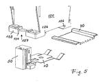
- the spring tongue and spring angle should be placed on the - in Fig. 5 shown - support rail 90 come into contact with the support rail.
- the spring tongue 14 is provided with a depth T1 out of the plane 11 out.
- the spring angle 16 reach spring action by bending at a distance T2.
- the contact lug 12 is angled at right angles and serves to attach the contact socket 30.
- a push-in terminal 30 is shown in which an electrical connector (pin 80, see Fig. 3 or stranded terminal) is insertable.
- the plug should preferably hold without screwing it in the contact socket. To pull out the plug, use an unlocking tool.
- a hole 19 is formed, which has a plurality of locking teeth 19Z in the inner edge.
- a latching pin (or injection point) 103 is formed (see Fig. 4 ), whereupon the contact element 10 can be fastened, wherein the latching teeth latch onto the latching pin.
- a slot 13 is present, in which a corner of the housing 50, and the chamber closure 70 engages, so that a locking of the housing on the contact element is formed.
- latching teeth 11Z are likewise present, which are pressed against a plastic bead in the area of the slider attachment (see FIG Fig. 4 ) lock.
- FIG. 2 shows the housing 50 (left part of the figure) and the chamber closure 70 (right part of the figure 2B).
- the contact socket 30 is enclosed by the two-part housing (50, 70) of insulating material.
- Contact element 10 and housing (50, 70) form a two-part assembly.
- a chamber 60 for receiving the contact lug and for receiving the contact socket is present.
- the contact socket should be placed as a prefabricated part pushed onto the contact lug and held securely there.
- a rectangular notch 12 A is present, which serves as a retaining edge of the web 30 S for the attachable push-in terminal 30.
- Two embossments 12B are used to compensate for any existing differences in the distance between the thickness of the contact lug 12 and the thickness of the material of the contact socket 30 to ensure sufficient spring force.
- the insulating material housing 50 is pushed onto the contact element 10 after the contact bush has been fastened to the contact lug (see arrow on the left in FIG Fig. 1 ).
- an opening is present. This opening can be closed with a chamber closure 70. Chamber closure and accordingly also said opening have the height H and the width B.
- the chamber closure serves to stabilize the seat of the push-in clamp in the housing, therefore the chamber closure on the side S 1 is profiled to fit the clamp.
- a nose 72, 74 are formed in the lower and upper regions.
- the lugs 72, 74 are used for latching with the housing 50, wherein in the housing in the upper region corresponding window 56 and in the lower region a spring element 65 is formed.
- the spring element 65 is arranged via lateral slots 64 hingedly on the side surface of the housing.
- an unlocking opening 68 for engaging an unlocking tool for releasing the inserted plug pin.
- two grooves 52 are formed, which are adapted for locking with formed on the switching device projections 104 (see Fig. 4 and 5 ) interact.
- the grooves 52 extend in the direction perpendicular to the plane 11 of the contact element.
- FIG. 3 shows a view into the cut housing 50.
- the contact lug 12 is indicated a punctiform attachment of a spring clip 30 'on the contact lug 12.
- Die in Fig. 3 illustrated terminal 30 ' is intended as an alternative to the terminal design in Fig. 1 be understood.
- an inserted connector pin 80 can be seen.
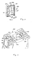
- the Fig. 4 shows a view of the bottom 102 of a switching device 100 with inserted contact element 10.
- Undercuts 106 are formed, which serve for locking with a support rail 90.
- a slider 110 is present, which interacts resiliently with the support rail.
- the fastening and locking elements of the switching device with the mounting rail are well known, and therefore require no further explanation.
- the position of the spring tongue 14 and the spring bracket 16 can be seen.
- the housing 50 On the left side of the Fig. 4 is the housing 50, which is visible from its underside.
- the latching of the housing with the switching device via grooves 52 and corresponding projections 104 on the baseboard 105 of the switching device. Grooves and protrusions are spaced from each other by the width W.
- the contact element hole 19 is formed with locking teeth 19Z, which cooperates with the locking pin 103 on the bottom 102 of the switching device and the contact element stop on the switching device.
- This type of attachment is to be understood as an example. It can also be provided to dispense with such an attachment to the underside of the switching device, since after sliding onto a mounting rail creates a separate stop, which requires no further holding means.
- the projections 104 in an opening 107 on the baseboard 105 (see also Fig. 5 ) of the switching device, which are merged with the grooves 52 are directed perpendicular to the housing bottom 102.
- an opening 107 on the baseboard 105 does not have to be a priori.
- the break-out piece may be prepared with predetermined breaking points on the baseboard 105, so that if necessary, the piece must be cracked out to form the opening 107.
- a complete assembly of the contact element is shown in its position below a switching device. The assembly is inserted from below into the opening 107.
Landscapes
- Engineering & Computer Science (AREA)
- Power Engineering (AREA)
- Switch Cases, Indication, And Locking (AREA)
- Breakers (AREA)
- Railway Tracks (AREA)
- Connector Housings Or Holding Contact Members (AREA)
Applications Claiming Priority (1)
| Application Number | Priority Date | Filing Date | Title |
|---|---|---|---|
| DE102006059826A DE102006059826A1 (de) | 2006-12-19 | 2006-12-19 | Kontaktelement zur Befestigung an einem auf einer Tragschiene aufzurastenden, elektrischen Schaltgerät |
Publications (3)
| Publication Number | Publication Date |
|---|---|
| EP1936744A2 true EP1936744A2 (fr) | 2008-06-25 |
| EP1936744A3 EP1936744A3 (fr) | 2010-01-20 |
| EP1936744B1 EP1936744B1 (fr) | 2012-02-22 |
Family
ID=39185768
Family Applications (1)
| Application Number | Title | Priority Date | Filing Date |
|---|---|---|---|
| EP07022524A Not-in-force EP1936744B1 (fr) | 2006-12-19 | 2007-11-20 | Appareil électrique avec élément de contact pour la fixation sur le même |
Country Status (3)
| Country | Link |
|---|---|
| EP (1) | EP1936744B1 (fr) |
| AT (1) | ATE546858T1 (fr) |
| DE (1) | DE102006059826A1 (fr) |
Cited By (2)
| Publication number | Priority date | Publication date | Assignee | Title |
|---|---|---|---|---|
| WO2011003605A1 (fr) * | 2009-07-10 | 2011-01-13 | Thomas Waible | Dispositif de mise à la terre pour fiche de prise de courant de sécurité, et fiche de prise de courant de sécurité correspondante |
| WO2015120951A1 (fr) * | 2014-02-13 | 2015-08-20 | Ellenberger & Poensgen Gmbh | Disjoncteur thermique de protection contre les surintensités |
Families Citing this family (1)
| Publication number | Priority date | Publication date | Assignee | Title |
|---|---|---|---|---|
| DE102013114261A1 (de) | 2013-12-17 | 2015-06-18 | Eaton Electrical Ip Gmbh & Co. Kg | Elektronikgehäuse eines Schaltgeräts und eine im Elektronikgehäuse montierbare Schutzkontaktanordnung |
Citations (1)
| Publication number | Priority date | Publication date | Assignee | Title |
|---|---|---|---|---|
| DE29905625U1 (de) | 1999-03-30 | 1999-06-10 | Festo AG & Co, 73734 Esslingen | Haltevorrichtung für Gehäuse von elektrischen Einrichtungen |
Family Cites Families (6)
| Publication number | Priority date | Publication date | Assignee | Title |
|---|---|---|---|---|
| DE8605786U1 (de) * | 1986-03-03 | 1986-04-17 | Albrecht Jung Gmbh, 7965 Ostrach | Geräteträger für NH-Sicherungsschalter |
| DE3732267C1 (en) * | 1987-09-25 | 1988-09-22 | Phoenix Elekt | Electrical terminal block |
| DE29515982U1 (de) * | 1995-09-29 | 1996-10-31 | Krone Ag, 14167 Berlin | Erdungsbügel, insbesondere zur Verwendung in einer Anschlußeinrichtung für die Fernmelde- und Datentechnik |
| DE19642086B4 (de) * | 1996-10-04 | 2006-06-08 | Wago Verwaltungsgesellschaft Mbh | Montage- und Kontaktträger für Tragschienen |
| US6940021B2 (en) * | 2002-09-30 | 2005-09-06 | Rockwell Automation Technologies, Inc. | Zero space component adapter for rail mounted terminal block relays |
| DE202005020655U1 (de) * | 2005-04-04 | 2006-06-29 | Ria-Btr Produktions-Gmbh | Trägerelement für Anschlussklemmen |
-
2006
- 2006-12-19 DE DE102006059826A patent/DE102006059826A1/de not_active Ceased
-
2007
- 2007-11-20 EP EP07022524A patent/EP1936744B1/fr not_active Not-in-force
- 2007-11-20 AT AT07022524T patent/ATE546858T1/de active
Patent Citations (1)
| Publication number | Priority date | Publication date | Assignee | Title |
|---|---|---|---|---|
| DE29905625U1 (de) | 1999-03-30 | 1999-06-10 | Festo AG & Co, 73734 Esslingen | Haltevorrichtung für Gehäuse von elektrischen Einrichtungen |
Cited By (4)
| Publication number | Priority date | Publication date | Assignee | Title |
|---|---|---|---|---|
| WO2011003605A1 (fr) * | 2009-07-10 | 2011-01-13 | Thomas Waible | Dispositif de mise à la terre pour fiche de prise de courant de sécurité, et fiche de prise de courant de sécurité correspondante |
| WO2015120951A1 (fr) * | 2014-02-13 | 2015-08-20 | Ellenberger & Poensgen Gmbh | Disjoncteur thermique de protection contre les surintensités |
| CN105993059A (zh) * | 2014-02-13 | 2016-10-05 | 埃伦贝格尔及珀恩斯根有限公司 | 热过电流保护开关 |
| US10348000B2 (en) | 2014-02-13 | 2019-07-09 | Ellenberger & Poensgen Gmbh | Thermal overcurrent circuit breaker |
Also Published As
| Publication number | Publication date |
|---|---|
| ATE546858T1 (de) | 2012-03-15 |
| EP1936744B1 (fr) | 2012-02-22 |
| DE102006059826A1 (de) | 2008-07-03 |
| EP1936744A3 (fr) | 2010-01-20 |
Similar Documents
| Publication | Publication Date | Title |
|---|---|---|
| EP0735615B1 (fr) | Borne de jonction pour appareils électriques | |
| DE102010025930B4 (de) | Anschlussklemme | |
| DE10315668B4 (de) | Anschlußklemme | |
| EP3159974A1 (fr) | Borne d'alimentation électrique | |
| DE10013111A1 (de) | Adapterplatte und System zur Anbringung eines Bauelementes auf eine Montageunterlage | |
| EP3843221B1 (fr) | Cadre de support pour un connecteur | |
| EP1536519A1 (fr) | Borne de raccordement pour conducteur | |
| DE102006060989B4 (de) | System zur Sicherung und zum Schutz einer elektrischen Steckverbindung und Aufsatzteil für diese Steckverbindung | |
| WO2000034971A1 (fr) | Disjoncteur de protection de circuits electriques de vehicules routiers | |
| EP1818964A2 (fr) | Barrette de fusibles avec contacts de sortie latéraux et module adaptateur latéral | |
| DE102018124583A1 (de) | Klemmenanordnung mit einer Stromschiene | |
| DE102006057766B4 (de) | Befestigungsvorrichtung von Elektronikmodulen auf Tragschiene | |
| DE19949387A1 (de) | Kontaktteil für Anschlussklemme | |
| DE20003081U1 (de) | Kabelhaltevorrichtung | |
| EP1936744B1 (fr) | Appareil électrique avec élément de contact pour la fixation sur le même | |
| DE1465705B1 (de) | Elektrischer Schnappschalter mit Drueckerhebel | |
| DE102011101078B4 (de) | Elektrisches Installationsschaltgerät mit einer Schnellbefestigungsvorrichtung | |
| DE102018106185B4 (de) | Kontaktelement mit einem Kontaktkörper und einem daran angeordneten Federelement | |
| DE202008010347U1 (de) | Steckbarer PE-Schutzkontakt | |
| DE19838432C1 (de) | Installationsgerät zur Montage an einer Hutschiene | |
| EP2192665B1 (fr) | Cassette d'installation au sol pour appareils d'installation électriques | |
| EP2339710A2 (fr) | Appareil d'installation électrique | |
| EP2489100B1 (fr) | Borne à vis avec couvercle et appareil de coupure d'installation | |
| DE102018119525A1 (de) | Abgriffsteckverbinder und Schutzerdungskontakt hierzu | |
| EP1480307A1 (fr) | Adaptateur pour un rail de support |
Legal Events
| Date | Code | Title | Description |
|---|---|---|---|
| PUAI | Public reference made under article 153(3) epc to a published international application that has entered the european phase |
Free format text: ORIGINAL CODE: 0009012 |
|
| AK | Designated contracting states |
Kind code of ref document: A2 Designated state(s): AT BE BG CH CY CZ DE DK EE ES FI FR GB GR HU IE IS IT LI LT LU LV MC MT NL PL PT RO SE SI SK TR |
|
| AX | Request for extension of the european patent |
Extension state: AL BA HR MK RS |
|
| PUAL | Search report despatched |
Free format text: ORIGINAL CODE: 0009013 |
|
| AK | Designated contracting states |
Kind code of ref document: A3 Designated state(s): AT BE BG CH CY CZ DE DK EE ES FI FR GB GR HU IE IS IT LI LT LU LV MC MT NL PL PT RO SE SI SK TR |
|
| AX | Request for extension of the european patent |
Extension state: AL BA HR MK RS |
|
| RAP1 | Party data changed (applicant data changed or rights of an application transferred) |
Owner name: EATON INDUSTIES GMBH |
|
| RAP1 | Party data changed (applicant data changed or rights of an application transferred) |
Owner name: EATON INDUSTRIES GMBH |
|
| 17P | Request for examination filed |
Effective date: 20100709 |
|
| 17Q | First examination report despatched |
Effective date: 20100809 |
|
| AKX | Designation fees paid |
Designated state(s): AT BE BG CH CY CZ DE DK EE ES FI FR GB GR HU IE IS IT LI LT LU LV MC MT NL PL PT RO SE SI SK TR |
|
| GRAP | Despatch of communication of intention to grant a patent |
Free format text: ORIGINAL CODE: EPIDOSNIGR1 |
|
| RTI1 | Title (correction) |
Free format text: ELECTRIC SWITCHING DEVICE WITH CONTACT ELEMENT FOR MOUNTING ON THE SAME |
|
| GRAS | Grant fee paid |
Free format text: ORIGINAL CODE: EPIDOSNIGR3 |
|
| GRAA | (expected) grant |
Free format text: ORIGINAL CODE: 0009210 |
|
| AK | Designated contracting states |
Kind code of ref document: B1 Designated state(s): AT BE BG CH CY CZ DE DK EE ES FI FR GB GR HU IE IS IT LI LT LU LV MC MT NL PL PT RO SE SI SK TR |
|
| REG | Reference to a national code |
Ref country code: GB Ref legal event code: FG4D Free format text: NOT ENGLISH |
|
| REG | Reference to a national code |
Ref country code: CH Ref legal event code: EP |
|
| REG | Reference to a national code |
Ref country code: AT Ref legal event code: REF Ref document number: 546858 Country of ref document: AT Kind code of ref document: T Effective date: 20120315 |
|
| REG | Reference to a national code |
Ref country code: NL Ref legal event code: T3 |
|
| REG | Reference to a national code |
Ref country code: IE Ref legal event code: FG4D Free format text: LANGUAGE OF EP DOCUMENT: GERMAN |
|
| REG | Reference to a national code |
Ref country code: SE Ref legal event code: TRGR |
|
| REG | Reference to a national code |
Ref country code: DE Ref legal event code: R096 Ref document number: 502007009309 Country of ref document: DE Effective date: 20120419 |
|
| LTIE | Lt: invalidation of european patent or patent extension |
Effective date: 20120222 |
|
| PG25 | Lapsed in a contracting state [announced via postgrant information from national office to epo] |
Ref country code: IS Free format text: LAPSE BECAUSE OF FAILURE TO SUBMIT A TRANSLATION OF THE DESCRIPTION OR TO PAY THE FEE WITHIN THE PRESCRIBED TIME-LIMIT Effective date: 20120622 Ref country code: LT Free format text: LAPSE BECAUSE OF FAILURE TO SUBMIT A TRANSLATION OF THE DESCRIPTION OR TO PAY THE FEE WITHIN THE PRESCRIBED TIME-LIMIT Effective date: 20120222 |
|
| PG25 | Lapsed in a contracting state [announced via postgrant information from national office to epo] |
Ref country code: PT Free format text: LAPSE BECAUSE OF FAILURE TO SUBMIT A TRANSLATION OF THE DESCRIPTION OR TO PAY THE FEE WITHIN THE PRESCRIBED TIME-LIMIT Effective date: 20120622 Ref country code: LV Free format text: LAPSE BECAUSE OF FAILURE TO SUBMIT A TRANSLATION OF THE DESCRIPTION OR TO PAY THE FEE WITHIN THE PRESCRIBED TIME-LIMIT Effective date: 20120222 Ref country code: FI Free format text: LAPSE BECAUSE OF FAILURE TO SUBMIT A TRANSLATION OF THE DESCRIPTION OR TO PAY THE FEE WITHIN THE PRESCRIBED TIME-LIMIT Effective date: 20120222 Ref country code: GR Free format text: LAPSE BECAUSE OF FAILURE TO SUBMIT A TRANSLATION OF THE DESCRIPTION OR TO PAY THE FEE WITHIN THE PRESCRIBED TIME-LIMIT Effective date: 20120523 |
|
| REG | Reference to a national code |
Ref country code: IE Ref legal event code: FD4D |
|
| PG25 | Lapsed in a contracting state [announced via postgrant information from national office to epo] |
Ref country code: CY Free format text: LAPSE BECAUSE OF FAILURE TO SUBMIT A TRANSLATION OF THE DESCRIPTION OR TO PAY THE FEE WITHIN THE PRESCRIBED TIME-LIMIT Effective date: 20120222 |
|
| PG25 | Lapsed in a contracting state [announced via postgrant information from national office to epo] |
Ref country code: RO Free format text: LAPSE BECAUSE OF FAILURE TO SUBMIT A TRANSLATION OF THE DESCRIPTION OR TO PAY THE FEE WITHIN THE PRESCRIBED TIME-LIMIT Effective date: 20120222 Ref country code: DK Free format text: LAPSE BECAUSE OF FAILURE TO SUBMIT A TRANSLATION OF THE DESCRIPTION OR TO PAY THE FEE WITHIN THE PRESCRIBED TIME-LIMIT Effective date: 20120222 Ref country code: SI Free format text: LAPSE BECAUSE OF FAILURE TO SUBMIT A TRANSLATION OF THE DESCRIPTION OR TO PAY THE FEE WITHIN THE PRESCRIBED TIME-LIMIT Effective date: 20120222 Ref country code: EE Free format text: LAPSE BECAUSE OF FAILURE TO SUBMIT A TRANSLATION OF THE DESCRIPTION OR TO PAY THE FEE WITHIN THE PRESCRIBED TIME-LIMIT Effective date: 20120222 Ref country code: IE Free format text: LAPSE BECAUSE OF FAILURE TO SUBMIT A TRANSLATION OF THE DESCRIPTION OR TO PAY THE FEE WITHIN THE PRESCRIBED TIME-LIMIT Effective date: 20120222 Ref country code: CZ Free format text: LAPSE BECAUSE OF FAILURE TO SUBMIT A TRANSLATION OF THE DESCRIPTION OR TO PAY THE FEE WITHIN THE PRESCRIBED TIME-LIMIT Effective date: 20120222 Ref country code: PL Free format text: LAPSE BECAUSE OF FAILURE TO SUBMIT A TRANSLATION OF THE DESCRIPTION OR TO PAY THE FEE WITHIN THE PRESCRIBED TIME-LIMIT Effective date: 20120222 |
|
| PG25 | Lapsed in a contracting state [announced via postgrant information from national office to epo] |
Ref country code: SK Free format text: LAPSE BECAUSE OF FAILURE TO SUBMIT A TRANSLATION OF THE DESCRIPTION OR TO PAY THE FEE WITHIN THE PRESCRIBED TIME-LIMIT Effective date: 20120222 |
|
| PLBE | No opposition filed within time limit |
Free format text: ORIGINAL CODE: 0009261 |
|
| STAA | Information on the status of an ep patent application or granted ep patent |
Free format text: STATUS: NO OPPOSITION FILED WITHIN TIME LIMIT |
|
| 26N | No opposition filed |
Effective date: 20121123 |
|
| PGFP | Annual fee paid to national office [announced via postgrant information from national office to epo] |
Ref country code: FR Payment date: 20121113 Year of fee payment: 6 Ref country code: DE Payment date: 20121130 Year of fee payment: 6 |
|
| PGFP | Annual fee paid to national office [announced via postgrant information from national office to epo] |
Ref country code: IT Payment date: 20121120 Year of fee payment: 6 Ref country code: SE Payment date: 20121107 Year of fee payment: 6 |
|
| REG | Reference to a national code |
Ref country code: DE Ref legal event code: R097 Ref document number: 502007009309 Country of ref document: DE Effective date: 20121123 |
|
| PGFP | Annual fee paid to national office [announced via postgrant information from national office to epo] |
Ref country code: NL Payment date: 20121112 Year of fee payment: 6 |
|
| PG25 | Lapsed in a contracting state [announced via postgrant information from national office to epo] |
Ref country code: ES Free format text: LAPSE BECAUSE OF FAILURE TO SUBMIT A TRANSLATION OF THE DESCRIPTION OR TO PAY THE FEE WITHIN THE PRESCRIBED TIME-LIMIT Effective date: 20120602 |
|
| BERE | Be: lapsed |
Owner name: EATON INDUSTRIES G.M.B.H. Effective date: 20121130 |
|
| REG | Reference to a national code |
Ref country code: CH Ref legal event code: PL |
|
| GBPC | Gb: european patent ceased through non-payment of renewal fee |
Effective date: 20121120 |
|
| PG25 | Lapsed in a contracting state [announced via postgrant information from national office to epo] |
Ref country code: LI Free format text: LAPSE BECAUSE OF NON-PAYMENT OF DUE FEES Effective date: 20121130 Ref country code: CH Free format text: LAPSE BECAUSE OF NON-PAYMENT OF DUE FEES Effective date: 20121130 Ref country code: BG Free format text: LAPSE BECAUSE OF FAILURE TO SUBMIT A TRANSLATION OF THE DESCRIPTION OR TO PAY THE FEE WITHIN THE PRESCRIBED TIME-LIMIT Effective date: 20120522 |
|
| PG25 | Lapsed in a contracting state [announced via postgrant information from national office to epo] |
Ref country code: BE Free format text: LAPSE BECAUSE OF NON-PAYMENT OF DUE FEES Effective date: 20121130 |
|
| PG25 | Lapsed in a contracting state [announced via postgrant information from national office to epo] |
Ref country code: MT Free format text: LAPSE BECAUSE OF FAILURE TO SUBMIT A TRANSLATION OF THE DESCRIPTION OR TO PAY THE FEE WITHIN THE PRESCRIBED TIME-LIMIT Effective date: 20120222 Ref country code: GB Free format text: LAPSE BECAUSE OF NON-PAYMENT OF DUE FEES Effective date: 20121120 |
|
| REG | Reference to a national code |
Ref country code: AT Ref legal event code: MM01 Ref document number: 546858 Country of ref document: AT Kind code of ref document: T Effective date: 20121130 |
|
| PG25 | Lapsed in a contracting state [announced via postgrant information from national office to epo] |
Ref country code: AT Free format text: LAPSE BECAUSE OF NON-PAYMENT OF DUE FEES Effective date: 20121130 |
|
| PG25 | Lapsed in a contracting state [announced via postgrant information from national office to epo] |
Ref country code: MC Free format text: LAPSE BECAUSE OF NON-PAYMENT OF DUE FEES Effective date: 20121130 Ref country code: TR Free format text: LAPSE BECAUSE OF FAILURE TO SUBMIT A TRANSLATION OF THE DESCRIPTION OR TO PAY THE FEE WITHIN THE PRESCRIBED TIME-LIMIT Effective date: 20120222 |
|
| PG25 | Lapsed in a contracting state [announced via postgrant information from national office to epo] |
Ref country code: LU Free format text: LAPSE BECAUSE OF NON-PAYMENT OF DUE FEES Effective date: 20121120 |
|
| REG | Reference to a national code |
Ref country code: NL Ref legal event code: V1 Effective date: 20140601 |
|
| REG | Reference to a national code |
Ref country code: SE Ref legal event code: EUG |
|
| PG25 | Lapsed in a contracting state [announced via postgrant information from national office to epo] |
Ref country code: HU Free format text: LAPSE BECAUSE OF FAILURE TO SUBMIT A TRANSLATION OF THE DESCRIPTION OR TO PAY THE FEE WITHIN THE PRESCRIBED TIME-LIMIT Effective date: 20071120 |
|
| REG | Reference to a national code |
Ref country code: FR Ref legal event code: ST Effective date: 20140731 |
|
| PG25 | Lapsed in a contracting state [announced via postgrant information from national office to epo] |
Ref country code: SE Free format text: LAPSE BECAUSE OF NON-PAYMENT OF DUE FEES Effective date: 20131121 Ref country code: NL Free format text: LAPSE BECAUSE OF NON-PAYMENT OF DUE FEES Effective date: 20140601 Ref country code: IT Free format text: LAPSE BECAUSE OF NON-PAYMENT OF DUE FEES Effective date: 20131120 Ref country code: DE Free format text: LAPSE BECAUSE OF NON-PAYMENT OF DUE FEES Effective date: 20140603 |
|
| REG | Reference to a national code |
Ref country code: DE Ref legal event code: R119 Ref document number: 502007009309 Country of ref document: DE Effective date: 20140603 |
|
| PG25 | Lapsed in a contracting state [announced via postgrant information from national office to epo] |
Ref country code: FR Free format text: LAPSE BECAUSE OF NON-PAYMENT OF DUE FEES Effective date: 20131202 |