EP1936754A2 - Connecteur à fiches doté d'un boîtier comportant un élément d'actionnement et un moyen d'accrochage - Google Patents
Connecteur à fiches doté d'un boîtier comportant un élément d'actionnement et un moyen d'accrochage Download PDFInfo
- Publication number
- EP1936754A2 EP1936754A2 EP07024492A EP07024492A EP1936754A2 EP 1936754 A2 EP1936754 A2 EP 1936754A2 EP 07024492 A EP07024492 A EP 07024492A EP 07024492 A EP07024492 A EP 07024492A EP 1936754 A2 EP1936754 A2 EP 1936754A2
- Authority
- EP
- European Patent Office
- Prior art keywords
- housing
- latching means
- connector according
- latching
- actuating element
- Prior art date
- Legal status (The legal status is an assumption and is not a legal conclusion. Google has not performed a legal analysis and makes no representation as to the accuracy of the status listed.)
- Withdrawn
Links
Images





Classifications
-
- H—ELECTRICITY
- H01—ELECTRIC ELEMENTS
- H01R—ELECTRICALLY-CONDUCTIVE CONNECTIONS; STRUCTURAL ASSOCIATIONS OF A PLURALITY OF MUTUALLY-INSULATED ELECTRICAL CONNECTING ELEMENTS; COUPLING DEVICES; CURRENT COLLECTORS
- H01R13/00—Details of coupling devices of the kinds covered by groups H01R12/70 or H01R24/00 - H01R33/00
- H01R13/62—Means for facilitating engagement or disengagement of coupling parts or for holding them in engagement
- H01R13/627—Snap or like fastening
- H01R13/6271—Latching means integral with the housing
- H01R13/6273—Latching means integral with the housing comprising two latching arms
Definitions
- the invention relates to a connector for electrical contacts according to claim 1 and a housing connector according to claim 19.
- a connector is known with an end cap, wherein the end cap is pushed onto a housing with a pin header by means of a lever mechanism by pivoting a lever by means of a gear on the housing.
- the object of the invention is to provide a simplified connector and a simplified housing for a connector, wherein the mounting of the connector is still easily possible.
- the object of the invention is achieved by the connector according to claim 1 and by the housing according to claim 19.
- An advantage of the connector is that no elaborate lever mechanism is required to connect a first housing to a second housing and that the first locking means is movably mounted on the first housing.
- the advantage is achieved in that at least one actuating element for applying a mounting force for inserting the first housing is provided in the second housing.
- a first latching means is provided on the first housing, which is resiliently connected to the first housing and can be brought into a mounting position with the actuator. During assembly of the two housings, the first latching means is deflected from a rest position. In an end position, the first locking means springs back into the rest position and comes into operative connection with a second locking means, which is formed on the second housing.
- the arrangement of the actuating element it is possible to move the first locking means in a mounting position closer to the first housing and to insert the first housing in the second housing.
- By forming the first and the second latching means on the first and second housings an automatic securing in the end position is achieved, so that the first housing is secured against unintentional release from the second housing.
- the spring element is designed in the form of a tab, wherein the tab holds the first latching means over a side surface of the first housing.
- the formation of the spring element as a tab is inexpensive and easy to perform.
- a sufficient pivotability of the first locking means by means of the actuating element is provided by the tab.
- a compact design is obtained by the arrangement of the first locking means on a side surface of the first housing, which is well suited for insertion of the first housing into a receiving opening of the second housing.
- two spring elements are provided, which are spaced apart from each other and connect the actuating element and the first latching means with the first housing.
- the two spring elements are arranged in such a manner that the first latching means is held over a side surface of the first housing at a predetermined distance.
- the two spring elements may be in the form of two tabs.
- the at least one tab is attached to an upper end portion of the first housing and has a bending portion of more than 90 °, which is connected to the first latching means.
- the spring element and the first latching means are formed integrally with the first housing.
- the first latching means in the form of a latching hook is formed, wherein the second latching means is designed in the form of a latching recess, in which the latching hook compresses in the end position and secures the first housing against removal from the second housing.
- the formation of the first latching means as latching hooks and the formation of the second latching means in the form of a latching recess is easy to carry out, wherein the latching hook and the latching recess represent reliable means for securing the first housing to the second housing.
- the first latching means is plate-shaped, wherein the first latching means is arranged substantially parallel to the side surface of the first housing. Due to the plate-shaped design of the first locking means and the parallel arrangement to the side surface of the first housing a compact design is given, so that the receiving opening of the second housing may have a small cross-section.
- the plate-shaped locking means When inserting the first housing in the second housing, the plate-shaped locking means is deflected from a rest position in the direction of the side surface of the first housing and upon reaching the end position, the plate-shaped locking means springs back into the rest position, in which case the first locking means in a safety position is located in which a removal of the first housing is hardly possible.
- the actuating element is designed in the form of a strip-shaped surface which is arranged transversely to a longitudinal axis of the first housing.
- at least two strip-shaped surfaces can be provided parallel and spaced as an actuating element.
- the actuating element is designed in the form of two webs, which are arranged parallel to one another, wherein a groove is provided between the webs, which also runs parallel to the webs. In this way, an improved attack surface for a tool or the hand of an operator is provided.
- the actuating element is connected to the housing via the at least one tab. In this way it is possible to maintain the compact design of the first housing and still provide an actuator. By fixing the actuating element via the spring element on the first housing, the actuating element is at least in a rest position laterally spaced from the housing. As a result, easy access to the actuator is possible.
- the actuating element is connected via two spring elements to the first housing.
- the two spring elements are laterally spaced from each other. Due to the lateral spacing of the two spring elements, the force introduced via the actuating element when the first housing is inserted is distributed more uniformly to the first housing.
- the free space between the two spring elements provides good access to the actuating element, so that a relatively large tool can be attached to the actuating element. When assembling by hand In addition, a relatively large area is available for acting on the actuating element.
- the first housing has on the side surface on which the actuating element is arranged, a contact edge, to which the actuating element is brought into abutment upon mating of the first and second housing. In this way, a safe and reliable introduction of the assembly force is made possible in the first housing.
- a stop element for the latching hook is provided on the first housing, wherein the stop element prevents a lateral deflection of the first latching means from the latching position.
- a high rigidity is achieved by the plate-shaped design of the first locking means despite a small thickness of the first locking means. Due to the high rigidity, the force that allows removal of the first housing from the second housing without releasing the first locking means, significantly increased. Only from a relatively high withdrawal force can be done by damage to the first or second locking means peeling off the first housing from the second housing.
- the second latching means is arranged on an inner side of a housing wall of the second housing, wherein the housing wall has an opening in the region of the second latching means to provide an access opening for releasing the first latching means.
- the second latching means is designed in the form of a plate element, wherein a recess for at least partially receiving the first latching means is provided on the plate element. This allows a simple design of the second locking means.
- first locking means are provided on opposite sides of the first housing.
- second locking means are provided on opposite sides of the second housing. The arrangement of locking means on two opposite sides of the first housing a reliable backup of the first housing against unintentional removal from the second housing is possible.
- actuating elements are provided on opposite sides.
- both the two first latching means and the two second latching means and the two actuating elements are formed identically on the two sides of the first housing.
- Fig. 1 shows in a perspective view a first housing 1, which may be in the form of a female housing.
- the first housing 1 is substantially cuboid-shaped and has on a rear side 2 contact openings 3 for receiving electrical contacts.
- the first housing 1 is formed mirror-symmetrically with respect to a center plane which is arranged parallel to the two wide side surfaces 5, 6.
- a hinged pivot bracket 7 is provided, which is fastened with two arms 8, 9 on the first side surface 5 of the first housing 1. Free ends of the first and second arms 8, 9 are connected to a transverse web 10.
- the crossbar 10 has on an inner side a cross-sectionally hook-shaped further web 11.
- the further web 11 is associated with a securing groove 12, which is formed on the first side surface 5.
- the securing groove 12 has a hook-shaped profile in cross-section, so that the further web 11 can be hooked to the securing groove 12.
- the swivel bracket 7 has a substantially U-shape, which surrounds a central space 13. The swivel bracket 7 and the center space 13 are arranged in a central portion of the first side surface 5. Below the securing groove 12, a contact portion 14 is provided on the first housing 1. Above connecting areas, in which the first and second arms 8, 9 are connected to the first side surface 5, there are two webs 15, 16 formed, which are arranged on an axis and a distance 17 from each other. Depending on the chosen embodiment, the first and second arms 8, 9 of the swivel bracket 7 may also be attached to the first and second webs 15, 16.
- first and second arms 8, 9 are connected on an underside of the first and second webs 15, 16 to the first and second webs 15, 16.
- the first and second webs 15, 16 are L-shaped in cross-section, the longer leg being fixed to the first side surface 5, and being arranged substantially perpendicular to the first side surface.
- the first and second arms 8, 9 are attached to the short leg via a film hinge.
- the first housing and the swivel bracket 7 may be integrally formed of the same material, such as plastic.
- first and a second abutment surface 18, 19 is formed on one of the underside opposite top of the first and second webs 15, 16 each have a first and a second abutment surface 18, 19 is formed.
- the first and the second contact surface 18, 19 is arranged in the illustrated embodiment substantially perpendicular to the first side surface 5 and in a plane.
- first and the second web 15, 16 two spring elements 20, 21 are provided, which are connected to the first side surface 5, wherein the first and the second spring element 20, 21 are formed in the form of tabs in particular spring tabs.
- the first and the second spring element 20, 21 are laterally spaced from each other and each connected to a first end in the upper edge region of the first side surface 5 adjacent to the back 2 of the first housing 1 with the first housing 1.
- Second ends of the first and second spring members 20, 21 are connected to a crossbar 22 at a fixed lateral distance.
- the first and second spring members 20, 21 have a bending portion between the first and second ends of at least 90 °.
- the first and the second spring element 20, 21 extend parallel to the first side surface 5 upwards and are guided in a bending section to the outside and back down again approximately parallel to the first side surface 5.
- the crossbar 22 extends transversely to a longitudinal axis of the first housing 1.
- the crossbar 22 has two end portions, which are arranged above the first and the second web 15, 16.
- a first latching means 25 is formed, which extends in the region of the distance 17 between the first and the second web 15, 16 downwards in the direction of the contact portion 14.
- the first locking means 25 is formed in the illustrated embodiment in the form of a plate-shaped latching hook with a latching nose 26.
- Under plate-shaped is understood a geometry whose width and length is significantly greater than the thickness thereof. For example, the width and length may be twice the thickness.
- finger-shaped latching means in particular catch hooks, whose width corresponds approximately to their thickness.
- the first locking means 25 is arranged in the region above the central space 13 of the swivel bracket.
- the latching hook 25 has a longitudinal edge 27, which is formed opposite to the latching lug 26. Adjacent to the longitudinal edge 27, a pin 28 is provided as a stop element on the first housing 1. The pin 28 prevents excessive lateral deflection of the first locking means 25 away from the second locking means, with which the locking lug is locked in the end position.
- the pin 28 is in the central space 13 or in a partial section, as in Fig. 1 is shown, the second arm 9 is arranged.
- the pin 28 is formed integrally with the first housing 1, for example.
- the crossbar 22 has in the illustrated embodiment, three parallel transverse webs 29, 30, 31, which are spaced by grooves 32, 33.
- the grooves have, for example, a similar width as the transverse webs 29, 30, 31.
- One The first transverse web 29, to which the first and the second spring element 20, 21 are connected, has an actuating surface 34, which is arranged substantially perpendicular to the first side surface 5.
- the second and the third transverse web on an actuating surface which are arranged substantially parallel to the actuating surface of the first crosspiece.
- the first latching means 25 is held resiliently in a rest position on the first housing 1 via the spring elements 20, 21.
- the spring elements, the first latching means and the crossbar may be integrally formed with the first housing and for example made of plastic.
- a second pivot bracket is provided on the second side surface 6.
- the second pivot bracket is formed identical to the first pivot bracket in the selected embodiment.
- the further first and the further second spring element are formed identical to the first and the second spring element in the selected embodiment.
- the further first latching means is identical to the first latching means.
- a further pin is provided as a stop element for the further first latching means.
- Fig. 2 shows a view from a contact side 38 on the first housing 1, wherein the contact side 38 is formed opposite to the back 2.
- contact holes 47 are provided, can be inserted via the second contacts in the contact portion 14 of the first housing 1.
- the contact side 38 is arranged at right angles to the longitudinal axis of the first housing.
- Fig. 3 shows the first housing 1, wherein electrical leads 39 are inserted with first contacts 4 via the contact openings 3 on the back 2 of the first housing 1 in the first housing 1.
- a further securing groove 44 is provided.
- Fig. 4 shows a cross section through the first housing 1, in which contacts 4 are mounted.
- the contacts 4 have contact sockets 45, which are arranged in contact spaces 46 of the contact section 14.
- the contact spaces 46 are accessible via the contact holes 47 from the contact side 38 ago.
- the contact spaces 46 are connected via a constricted cross-section 48 with the contact openings 3.
- the side walls are reduced in thickness, so that lateral bending is possible.
- the side walls spring back into the starting position.
- the swivel bracket 7, 37 are engaged in the securing grooves 12, 44, so that a lateral bending of the narrowed cross-sections 48 is prevented.
- the three transverse webs 29, 30, 31 decrease in width from top to bottom.
- the first transverse web 29 protrudes farther from an upper side of the first latching means 25 than the second transverse web 30.
- the third transverse web 31 protrudes less far from the upper side of the first latching means 25 than the second transverse web 30.
- Fig. 5 shows the first housing 1 with inserted first contacts 4, which are connected to electrical lines 39, wherein the first and the second pivot bracket 7, 37 are hooked into the securing grooves 12, 44.
- first and second pivoting brackets 7, 37 are arranged substantially parallel to the first and second side surfaces 5, 6.
- the first and the further first latching means 25, 43 are in a fixed distance to the first and second side surface 5, 6 and still outside of the center space 13 of the first and the second pivot bracket 7, 37 in a rest position.
- Fig. 6 shows a further perspective view of the first housing 1, wherein the first locking means 25 and the further first locking means 43 are arranged in the rest position between the first and the second web 15, 16 and the other first and second web 60, 61 and the pin 28 and the not shown further pin 62 up to the height of Longitudinal edge 27 of the first and the further first locking means 25, 43 protrude from the side surfaces of the housing.
- a lateral deflection of the first and second latching means 25, 43 is limited in the direction of the pin 28 and by the further pin 62.
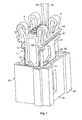
- Fig. 7 shows the first housing 1 when inserted into the second housing 49.
- the second housing 49 has a corresponding to the cross section of the first housing 1 formed receiving opening 50.
- a mounting force which is shown in the form of arrows F
- the actuators ie on the crossbars 22, 42.
- the first transverse bar 22 is placed on the first and second abutment surfaces 18, 19 of the first and second webs 15, 16.
- the further transverse bar 42 is placed on abutment surfaces of the further first and second webs 60, 61.
- the first housing 1 with the contact side 38 is pushed forward in the longitudinal direction into the receiving opening 50.
- first or the second latching means 25, 43 is pressed in the direction of the first and the second side surface 5, 6 of the first housing 1 to the first housing 1 in order to fit into the receiving opening 50.
- At least the locking lug 26 of the first and the further first locking means 25, 43 covers a plate member 51 and a further plate member 63 of a first and a second further side wall 52, 53 of the second housing 49.
- the plate member 51 and the further plate member 63 may in the form of a thicker version of the first or second further side wall 52, 53 may be formed.
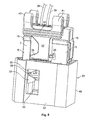
- Fig. 8 shows the connector with the second housing 49 and a partially inserted first housing 1.
- the second housing 49 openings 55 on.
- the plate member 51 and the further plate member 63 are arranged with recesses 56 on the inside.
- the recess 56 is adapted in the contour in cross-section to the latching lug 26, so that the latching lug 26 can spring out into the latching recess 56 upon reaching the latching recess 56.
- FIG. 9 This position is in which the first housing 1 is inserted into the end position in the second housing 49.
- the latching lugs 26 of the first and further first latching means 25, 43 are spring-loaded into the latching recesses 56, so that pulling out the first housing 1 by the first and further first latching means 25, 43 in the form of the latching recess 56 formed second and further second Locking means is prevented.
- the latching lugs 26 of the first and the further first latching means 25, 43 are pressed inwards in the direction of the first and the second side surface 5, 6 from the latching recesses 56 and at the same time the first housing 1 pulled out of the second housing 49.
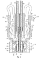
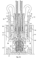
- Fig. 10 shows a cross section through the connector in the assembled state, wherein the first housing 1 is inserted and secured in the second housing 49.
- the second housing 49 has a pin header 57, are arranged in the second contacts 58.
- the second contacts 58 which are formed in the form of pins are inserted into the contact sockets 45 of the first contacts 4. In this way, an electrically conductive connection between the second contacts 58 of the second housing 49 and the first contacts 4 of the first housing 1 is made.
- the first and the further first latching means 25, 43 are biased in the mounted position to bias in the direction of the first housing 1 and are located on respectively associated holding blocks 59, 64 on.
- the holding blocks 59 are arranged on inner sides of the first further and the second further side wall 52, 53 of the second housing 49.
- a plate part 51, 63 are arranged on the inner sides of the holding blocks 59, 64, which is arranged in the same plane as the first and the further first latching means 25, 43.
- the recesses 56 are introduced, in which the latching lugs 26 of the first and the further first latching means 25, 43 are inserted. Due to the bias that biases the first and the further first locking means 25, 43 in the direction of the holding blocks 49 and the latching or the arrangement of the locking lugs 26 in the recesses 56 of the plate members 51, 63 is a secure and reliable latching or Abziehêt of the first housing 1 on the second housing 49.
- the plate members 51,63 have a sufficiently large distance D to the first and the second side surface 5, 6 of the first housing 1, which is greater than the thickness of the first and the further first locking means 25, 43. This makes it possible to push the first or the further first latching means 25, 43 into this intermediate space and to guide the first housing both into the second housing 49 and to pull it out of the second housing 49 again.
- a first locking means 25th and a crossbar 22 may be formed on one side of the first housing 1. Also, thereby a mounting mounting of the first and second housing 1, 49 are made possible. Due to the symmetrical arrangement of the first and further first locking means 25, 43 on opposite sides of the first housing 1, however, a more reliable securing is possible.
- first locking means 25 and the further first locking means 43 may also be designed differently.
- first latching means 25 and the further first latching means 43 may be formed in other forms.
- a bias of the first locking means and the further first locking means 25, 43 could be provided inwardly towards the first and the second side surface 5, 6 of the first housing 1 and for mounting or for disassembly of the first housing 1 of second housing 49, the first and the further first latching means 25, 43 are pulled outwardly into a corresponding free space away from the first and the second side surface 5, 6 of the first housing 1.
- the plate members 51, 63 having the recesses 56 are disposed adjacent to the first and second side surfaces 5, 6 in the second housing 49, respectively.
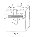
- the in Fig. 11 is shown, in each case only a first or a further first spring element 20, 40 is provided, which is connected to a first or a second side surface 5, 6 of the first housing 1 adjacent to the back 2 with one end to the first housing 1 , A second end of the first and the further first spring element 20, 40 is connected to a transverse bar 22.
- the first spring element 20 is arranged in the middle of the crossbar 22.
- the crossbar 22 may consist of a or a plurality of transverse webs 29, 30, 31 with grooves 32, 33 may be formed.
- the first transverse web 29 may be formed an actuating surface 34 for engaging a mounting force.
- the embodiment and the FIG. 11 also have a first locking means 25 with a spring element 20, 21 only on one side.
- a first locking means 25 with a spring element 20, 21 only on one side.
- only on one side of an actuator either directly on the first housing 1 or connected to the spring element and the first or further first locking means 25, 43 may be provided.
Landscapes
- Details Of Connecting Devices For Male And Female Coupling (AREA)
Applications Claiming Priority (1)
| Application Number | Priority Date | Filing Date | Title |
|---|---|---|---|
| DE200610060620 DE102006060620B4 (de) | 2006-12-21 | 2006-12-21 | Steckverbinder mit einem Gehäuse mit einem Betätigungselement und einem Rastmittel |
Publications (2)
| Publication Number | Publication Date |
|---|---|
| EP1936754A2 true EP1936754A2 (fr) | 2008-06-25 |
| EP1936754A3 EP1936754A3 (fr) | 2010-01-06 |
Family
ID=39226856
Family Applications (1)
| Application Number | Title | Priority Date | Filing Date |
|---|---|---|---|
| EP07024492A Withdrawn EP1936754A3 (fr) | 2006-12-21 | 2007-12-18 | Connecteur à fiches doté d'un boîtier comportant un élément d'actionnement et un moyen d'accrochage |
Country Status (2)
| Country | Link |
|---|---|
| EP (1) | EP1936754A3 (fr) |
| DE (1) | DE102006060620B4 (fr) |
Cited By (1)
| Publication number | Priority date | Publication date | Assignee | Title |
|---|---|---|---|---|
| CN110783768A (zh) * | 2018-12-30 | 2020-02-11 | 吴碧玉 | 一种用于彩超机的数据接口插座 |
Families Citing this family (1)
| Publication number | Priority date | Publication date | Assignee | Title |
|---|---|---|---|---|
| US12424789B2 (en) | 2020-08-05 | 2025-09-23 | Te Connectivity Solutions Gmbh | Housing for a connector of a connector system |
Family Cites Families (14)
| Publication number | Priority date | Publication date | Assignee | Title |
|---|---|---|---|---|
| GB2244181B (en) * | 1990-04-13 | 1994-12-21 | Oki Electric Cable | Double lock male/female type connector |
| FR2669897B1 (fr) * | 1990-11-30 | 1993-01-22 | Labinal | Dispositif de verrouillage de deux elements de boitier l'un par rapport a l'autre. |
| FR2709884B1 (fr) * | 1993-09-10 | 1995-10-13 | Cinch Connecteurs Sa | Perfectionnements aux boîtiers de connecteurs électriques. |
| JP2725759B2 (ja) * | 1993-11-18 | 1998-03-11 | 矢崎総業株式会社 | コネクタの結合検知装置及び短絡用接触子 |
| JP3074432B2 (ja) * | 1994-01-27 | 2000-08-07 | 矢崎総業株式会社 | ロック付きコネクタハウジング |
| JPH07307185A (ja) * | 1994-05-11 | 1995-11-21 | Yazaki Corp | コネクタのロック装置 |
| DE19743292A1 (de) * | 1997-09-30 | 1999-04-22 | Siemens Ag | Heckleuchten-Stecksystem-Familie mit Sicherungsbügel |
| GB9904214D0 (en) * | 1998-12-17 | 1999-04-21 | Drewnicki Richard | Electrical connectors |
| EP1107385B1 (fr) * | 1999-11-30 | 2011-11-09 | Tyco Electronics AMP GmbH | Connecteur électrique et/ou optique à douille ayant un bras d'arrêt |
| JP2001250636A (ja) * | 2000-03-03 | 2001-09-14 | Yazaki Corp | コネクタのロック構造 |
| JP3826799B2 (ja) * | 2001-03-02 | 2006-09-27 | 住友電装株式会社 | コネクタ |
| DE10314740A1 (de) * | 2003-03-31 | 2004-10-14 | Ghw Grote & Hartmann Gmbh | Steckverbindung mit Verriegelungseinrichtung |
| US20060025004A1 (en) * | 2004-07-29 | 2006-02-02 | Pei-Chen Chen | Electric coupler with positioning device |
| US6945807B1 (en) * | 2004-11-15 | 2005-09-20 | Hon Hai Precision Ind. Co., Ltd. | Cable end connector having integral latch means |
-
2006
- 2006-12-21 DE DE200610060620 patent/DE102006060620B4/de not_active Expired - Fee Related
-
2007
- 2007-12-18 EP EP07024492A patent/EP1936754A3/fr not_active Withdrawn
Cited By (1)
| Publication number | Priority date | Publication date | Assignee | Title |
|---|---|---|---|---|
| CN110783768A (zh) * | 2018-12-30 | 2020-02-11 | 吴碧玉 | 一种用于彩超机的数据接口插座 |
Also Published As
| Publication number | Publication date |
|---|---|
| DE102006060620B4 (de) | 2008-10-02 |
| DE102006060620A1 (de) | 2008-07-03 |
| EP1936754A3 (fr) | 2010-01-06 |
Similar Documents
| Publication | Publication Date | Title |
|---|---|---|
| EP3286806B1 (fr) | Châssis de maintien permettant de maintenir des modules de connecteur à fiche | |
| EP3734768B1 (fr) | Connecteur enfichable d'un raccord enfichable électrique ainsi que raccord enfichable électrique ainsi formé | |
| EP3586404B1 (fr) | Connexion élastique et connecteur rond comportant une pluralité de connexions élastiques | |
| WO2015128407A1 (fr) | Borne de liaison et contact de borne à ressort associé | |
| DE9017536U1 (de) | Steckverbindungsbuchse | |
| EP3843221B1 (fr) | Cadre de support pour un connecteur | |
| EP3375048B1 (fr) | Contact à enficher | |
| DE102018128042A1 (de) | Set aus Steckverbinder und Haltelement sowie Steckverbinder und Haltelement hierzu | |
| WO2023099476A1 (fr) | Connecteur mâle doté d'un système de verrouillage | |
| EP3855571A1 (fr) | Borne de raccordement et appareil électronique | |
| DE202023105328U1 (de) | Federkraftklemmanschluss und Leiteranschlussklemme | |
| DE19534205A1 (de) | Elektrischer Steckverbinder | |
| DE19916500B4 (de) | Aufbau eines Hebels für eine Steckverbindung, bei der die Steckelemente durch den Hebel verbunden werden | |
| EP2475057A1 (fr) | Dispositif de support de câble | |
| EP0139980B1 (fr) | Cable clamp | |
| DE102020126486A1 (de) | Halterahmen für einen Steckverbinder | |
| EP1528639A1 (fr) | Boítier de connecteur ayant un pont de court-circuit | |
| DE102006060620B4 (de) | Steckverbinder mit einem Gehäuse mit einem Betätigungselement und einem Rastmittel | |
| DE102019112612B3 (de) | Halterahmen und Steckverbinder mit einem derartigen Halterahmen | |
| DE102019106093B4 (de) | Halterahmen sowie Steckverbinder mit einem derartigen Halterahmen | |
| BE1032383B1 (de) | Halterahmen für einen Steckverbinder | |
| DE102018103999B4 (de) | Stromverteilergehäuse und Montageverfahren eines Sicherungsgehäuses in das Stromverteilergehäuse | |
| DE102023112873A1 (de) | Montagevorrichtung | |
| DE102024103084A1 (de) | Halterahmen für einen Steckverbinder | |
| DE102006020225B4 (de) | Reihenklemme mit einem Isoliergehäuse |
Legal Events
| Date | Code | Title | Description |
|---|---|---|---|
| PUAI | Public reference made under article 153(3) epc to a published international application that has entered the european phase |
Free format text: ORIGINAL CODE: 0009012 |
|
| AK | Designated contracting states |
Kind code of ref document: A2 Designated state(s): AT BE BG CH CY CZ DE DK EE ES FI FR GB GR HU IE IS IT LI LT LU LV MC MT NL PL PT RO SE SI SK TR |
|
| AX | Request for extension of the european patent |
Extension state: AL BA HR MK RS |
|
| PUAL | Search report despatched |
Free format text: ORIGINAL CODE: 0009013 |
|
| AK | Designated contracting states |
Kind code of ref document: A3 Designated state(s): AT BE BG CH CY CZ DE DK EE ES FI FR GB GR HU IE IS IT LI LT LU LV MC MT NL PL PT RO SE SI SK TR |
|
| AX | Request for extension of the european patent |
Extension state: AL BA HR MK RS |
|
| AKY | No designation fees paid | ||
| STAA | Information on the status of an ep patent application or granted ep patent |
Free format text: STATUS: THE APPLICATION IS DEEMED TO BE WITHDRAWN |
|
| 18D | Application deemed to be withdrawn |
Effective date: 20100707 |
|
| REG | Reference to a national code |
Ref country code: DE Ref legal event code: 8566 |