EP1936769B1 - Hilfsvorrichtung und Verfahren zur Angabe von Informationen, Hilfseinheit und elektrischer Schalter mit dieser Vorrichtung - Google Patents
Hilfsvorrichtung und Verfahren zur Angabe von Informationen, Hilfseinheit und elektrischer Schalter mit dieser Vorrichtung Download PDFInfo
- Publication number
- EP1936769B1 EP1936769B1 EP07354057.7A EP07354057A EP1936769B1 EP 1936769 B1 EP1936769 B1 EP 1936769B1 EP 07354057 A EP07354057 A EP 07354057A EP 1936769 B1 EP1936769 B1 EP 1936769B1
- Authority
- EP
- European Patent Office
- Prior art keywords
- information
- circuit breaker
- item
- auxiliary
- control
- Prior art date
- Legal status (The legal status is an assumption and is not a legal conclusion. Google has not performed a legal analysis and makes no representation as to the accuracy of the status listed.)
- Not-in-force
Links
- 238000000034 method Methods 0.000 title claims description 12
- 238000012546 transfer Methods 0.000 claims description 76
- 238000012545 processing Methods 0.000 claims description 43
- 230000003068 static effect Effects 0.000 claims description 43
- 230000008859 change Effects 0.000 claims description 20
- 230000008878 coupling Effects 0.000 claims description 16
- 238000010168 coupling process Methods 0.000 claims description 16
- 238000005859 coupling reaction Methods 0.000 claims description 16
- 230000007246 mechanism Effects 0.000 claims description 6
- 230000003287 optical effect Effects 0.000 claims description 5
- 230000004044 response Effects 0.000 claims description 5
- 238000005259 measurement Methods 0.000 claims description 3
- 239000004065 semiconductor Substances 0.000 description 19
- 230000007547 defect Effects 0.000 description 17
- 238000012360 testing method Methods 0.000 description 8
- 230000000903 blocking effect Effects 0.000 description 5
- 238000010586 diagram Methods 0.000 description 5
- 235000021183 entrée Nutrition 0.000 description 5
- 230000000630 rising effect Effects 0.000 description 5
- 230000008901 benefit Effects 0.000 description 3
- 239000003990 capacitor Substances 0.000 description 3
- 239000004020 conductor Substances 0.000 description 3
- 230000011664 signaling Effects 0.000 description 3
- 238000004146 energy storage Methods 0.000 description 2
- 230000010287 polarization Effects 0.000 description 2
- 230000008569 process Effects 0.000 description 2
- 238000004891 communication Methods 0.000 description 1
- 230000001419 dependent effect Effects 0.000 description 1
- 239000003517 fume Substances 0.000 description 1
- 239000000463 material Substances 0.000 description 1
- 238000007789 sealing Methods 0.000 description 1
Images


Classifications
-
- H—ELECTRICITY
- H02—GENERATION; CONVERSION OR DISTRIBUTION OF ELECTRIC POWER
- H02H—EMERGENCY PROTECTIVE CIRCUIT ARRANGEMENTS
- H02H3/00—Emergency protective circuit arrangements for automatic disconnection directly responsive to an undesired change from normal electric working condition with or without subsequent reconnection ; integrated protection
- H02H3/02—Details
- H02H3/04—Details with warning or supervision in addition to disconnection, e.g. for indicating that protective apparatus has functioned
Definitions
- the invention also relates to an auxiliary assembly of an electric circuit breaker comprising the auxiliary information transfer device.
- the invention also relates to a circuit breaker comprising said auxiliary assembly.
- the patent application EP 0 591 074 discloses an electric circuit breaker having auxiliary blocks providing signaling and / or control functions.
- One of the auxiliary blocks makes it possible to transfer information representative of a state of the circuit breaker, in particular information representative of the opening or closing of the main contacts of the circuit breaker.
- the processing means of the auxiliary information transfer devices of the prior art are generally initialized thanks to the information of the trigger signals. Such a process is not optimized for its reliability.
- the electrical faults generating the opening of main contacts of the circuit breaker comprise the thermal or differential type defects, the thermal type defects, and the differential type defects.
- the electrical faults that do not generate the opening of main contacts of the circuit breaker comprise any variation of the frequency relative to a reference, any variation of voltage with respect to a reference, and any failure in the measurement chain.
- the signals carrying the second information are in the form of a frame comprising a pulse whose duration is representative of the information carried by said signals.
- the processing means comprise a configuration input.
- the second piece of information is representative of an electrical fault of the thermal type and / or of the differential type.
- the auxiliary device comprises two control outputs for controlling the transfer of information on two static contacts for distinguishing distinctively information representative of a thermal-type electrical fault and information representative of a differential-type electrical fault.
- the processing means comprise timing means associated with the initialization means for authorizing the initialization when the time elapsed between the transfer of the second piece of information and the closing of the main contacts is less than a predetermined time delay, for example. example between 300 and 700 ms.
- the auxiliary initialization command is timed.
- the auxiliary device comprises means for adjusting the timing of the auxiliary opening control of an auxiliary switch.
- the first input is connected to the adjustment means to receive information representative of the delay.
- the auxiliary device comprises coupling means with a trigger of said circuit breaker for receiving signals carrying the second information representative of an electrical fault or of an auxiliary control, the second input being connected to said coupling means .
- the coupling means comprises an optical coupler and hermetic protection means.
- the auxiliary device comprises switching means connected to the at least one control output for switching at least one static contact and for posting on said contact at least one of said information.
- the auxiliary device has a standard form to be mounted in at least one compartment of said circuit breaker.
- the state transfer means comprise an electrical contact actuated by a mechanism of the circuit breaker.
- the state of the circuit breaker status means are arranged in a block of electrical terminals connected to the static contacts of said auxiliary device.
- the block of electrical terminals has a standard form to be mounted in at least one compartment of said circuit breaker.
- the invention also relates to an electric circuit breaker comprising an electronic release for triggering the opening of main contacts of said circuit breaker in response to at least one type of electrical fault, and an auxiliary assembly coupled to said electronic release, wherein said auxiliary assembly is such that described above, and wherein it is coupled to the trigger via the coupling means of the auxiliary information transfer device of said auxiliary assembly.
- the second piece of information is representative of an electrical fault of the thermal type and / or of the differential type.
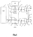
- the figure 1 is a block diagram of an auxiliary circuit breaker assembly having an auxiliary information transfer device in a fault report configuration with circuit breaker state change initialization.
- the figure 2 represents a block diagram of the processing means comprising means for selecting different configurations corresponding to given modes of operation.
- FIGS. 3a, 3b and 3c illustrate the operation of the auxiliary device in a fault report configuration with initialization by circuit breaker state change and in the case of a circuit breaker opening time less than a delay time.
- FIGS. 4a, 4b and 4c illustrate the operation of the auxiliary device in a fault report configuration with initialization by circuit breaker state change and in the case of a circuit breaker opening time greater than the delay time.
- FIGS. 5a, 5b and 5c illustrate the operation of the auxiliary device in a fault report configuration with initialization via the trigger of said circuit breaker.
- the figure 6 represents a more detailed diagram of an embodiment of the auxiliary device according to the invention.
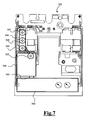
- the figure 7 represents an example of a front face of a circuit breaker with its associated auxiliary assembly comprising an auxiliary device and state transfer means arranged in a block of electrical terminals.
- the figure 8 represents a block diagram of an example of an auxiliary assembly according to an embodiment of the invention
- the figure 9 represents an example of a block of electrical terminals comprising the state transfer means.
- the figure 10 represents an embodiment of the information transfer method according to the invention.
- the auxiliary assembly shown in figure 1 comprises an auxiliary information transfer device 1, according to an embodiment of the invention, for reporting information representative of an electrical fault and / or a state of the circuit breaker.
- the auxiliary assembly also comprises state transfer means 2 for reporting the state of the circuit breaker, for example the opening O or the closing F of the main contacts of the circuit breaker.
- the auxiliary assembly is coupled to a trip unit 3 of the circuit breaker via the auxiliary device 1.
- the main function of the trip unit is to control the opening of the main contacts of the circuit breaker in response to certain electrical faults.
- the auxiliary device 1 for reporting the information of the figure 1 comprises coupling means 4 with the trigger 3. These coupling means allow the reception of signals from the trigger and carrying at least a second piece of information representative of an electrical fault or an auxiliary command.
- the auxiliary device 1 for reporting the information of the figure 1 comprises processing means 5, the latter having a second input 6 connected to the coupling means 4.
- the processing means comprise at least one output of commands.
- the processing means 5 comprise two control outputs 7 and 8, each of said control outputs allowing, in the case of the figure 1 , to control the report of the second information or a first information representative of a state of the circuit breaker.
- each output makes it possible to control, depending on the state of the circuit breaker, the report of the second piece of information representative of an electrical fault, or the report of the first piece of information representative of a state of the circuit breaker.
- the auxiliary device 1 comprises switching means connected to the at least one control output.
- the switching means comprise a first power semiconductor module 9 equipped with a control input 10 connected to the control output 7.
- the switching means also comprise a second power semiconductor module 11 equipped with a control input 12 connected to the control output 8.
- the first power semiconductor module 9 has an output 13 and a common output 14.
- the second power semiconductor module 11 has an output 15 and an output. common output 16.
- the common outputs 14 and 16 of each module are interconnected by a conductor 17.
- the switching means, and in particular the power semiconductor modules 9 and 11 of said switching means make it possible to switch to least one static contact and to defer on said contact the second or the first information.
- the output 13 of the first module 9 is connected to a first static contact 18, and the output 15 of the second module 11 is connected to a second static contact 19.
- One of the static contacts can allow the transfer of a type of defect predetermined, for example a SDT thermal type defect, and the other static contact may allow the transfer of another predetermined type of fault, for example an SDV differential type fault.
- the difference in voltage level on a static contact can make it possible to postpone the presence or absence of a predetermined type of fault.
- a low voltage level or a zero voltage may correspond to the absence of the predetermined fault type, while the presence of a high voltage level or a voltage may correspond to the presence of the same type default.
- the static contacts 18 and 19 may be connected to display means, such as light-emitting diodes, to display the information reported on these contacts and indicate the presence or absence of certain types of defects.
- the identification means may also make it possible to identify an auxiliary command in the second piece of information.
- the auxiliary command may be, for example, an auxiliary command for initializing or deactivating the at least one control output or an auxiliary command for opening an auxiliary switch.
- the signals carrying the second information may be in the form of a frame comprising pulses whose duration is representative of the information carried by said signals.
- the identification means make it possible to determine the duration of these pulses and to compare them with different values corresponding to predetermined information.
- the configuration input 32 of the processing means 5 makes it possible to select a configuration corresponding to an operating mode of the auxiliary device.
- the embodiment shown at figure 1 corresponds to a fault report SDX configuration with initialization by circuit breaker state change.
- the configuration input may make it possible to select other configurations such as an M2C fault report configuration with initialization via the trip unit of said circuit breaker or an auxiliary control SDTAM configuration of an auxiliary switch.
- the processing means 5 represented in the figure 1 comprise a first input 33 for receiving, in an SDX defect transfer configuration with initialization by circuit breaker state change, the first information representative of a state of said circuit breaker.
- the processing means 5 also include initialization means 34 of the control output for controlling, in the same SDX configuration, the transfer of the first information representative of a state, and this as a function of the second information and the first information.
- the processing means 5 may advantageously make it possible, in a first step, to control the transfer of the second piece of information, when the second piece of information is representative of a electrical fault corresponding to a fault generating an opening of the main contacts of the circuit breaker and, secondly, the initialization of the control output, when the first information is representative of a subsequent closure of the main contacts of said circuit breaker.
- the second piece of information is generally representative of an electrical fault of the SDT thermal type and / or of the SDV differential type.
- the two control outputs 7 and 8 make it possible to control the transfer of information, via the switching means 9 and 11, to two static contacts 18 and 19 for distinguishing distinctively information representative of an electrical fault of thermal type SDT and an electrical fault information of SDV differential type.
- Such an auxiliary information transfer device has an increased reliability, because the initialization is caused by information representative of the state of the circuit breaker and that this information comes from state transfer means detached from the trigger.
- the processing means may also comprise timing means associated with the initialization means for authorizing the initialization of the control output when the time elapsed between the transfer of the second information and the closing of the main contacts is less than a predetermined time delay.
- the delay time can range from 500 ms to 1 second, preferably from 300 to 700 ms. This delay ensures that the circuit breaker has changed state before resetting, which allows, for example, to overcome the problem of rebound in the contact.
- the processing means 51 represented in the figure 2 include, as in the figure 1 a second input 55, identification means 56 connected to the second input, a first input 57, two control outputs 58 and 59, initialization means 60 of the control outputs, and delay means 61 associated with the initialization means.
- the processing means 51 comprise elements dedicated to operation in the other two configurations M2C and SDTAM.
- delay means 62 associated initialization means 62 allow, in an SDTAM configuration to time the initialization of at least one of the command outputs 58 and / or 59.
- the configuration switch 52 and the configuration switch 53 of the figure 2 are represented in states allowing an SDX configuration of fault report with initialization by state change of the circuit breaker.
- the configuration switch 53 is in a state for connecting the first input 57, via the delay means 61, to the initialization means 60.
- the first information representative of a state O or F of said circuit breaker controls the initialization of the control outputs 58 and 59.
- the configuration switch 52 is, in turn, in an open state to disconnect the identification means of the initialization means.
- the processing means first make it possible to control the transfer of the second information available on the second input 55, when this information is representative of an electrical fault corresponding to a fault generating an opening.
- processing means also allow, in a second step, the initialization of the control outputs, when the first information available on the first input 57 is representative of a subsequent closure of the main contacts of said circuit breaker and when the time elapsed between the transfer the second information on the input 57 and the closure of the main contacts is less than a predetermined time delay.
- the Figures 3a to 3c illustrate the operation of the auxiliary device, in an SDX configuration, and when the opening of the circuit breaker following an electrical fault, extends over a period of less than the delay time.
- the signal 101 represented in figure 3a received on the second input 55, carries a second piece of information representative of a defect, in this case a predetermined type of defect.
- This signal comprises a pulse 102 whose duration makes it possible to identify the predetermined type of fault, for example an SDT thermal type or SDV differential type fault.
- the fault appears at time t0 and is identified at time t1 or shortly after, that is to say, at the earliest, at the falling edge 103 of pulse 102.
- the presence of this type of predetermined fault generates a change of state of the circuit breaker, in this case an opening of the main contacts, this information representative of a state being carried over to the first entry 57.
- the signal 104 received on the first input 57 has a rising edge 105 representative of the opening of the main contacts of the circuit breaker. This rising edge 105 of the signal 104 may occur shortly after the time t0.
- the signal 104 is maintained at a high level until the time t2 corresponding to a closure of the main contacts of the circuit breaker.
- a transfer command of the second information representative of the fault is sent to the control output 58 of the processing means.
- This second information is then reported, via the switching means, on the static contact or one of the static contacts for the transfer of the predetermined type of fault.
- the voltage 106 on this static contact represented in FIG. figure 3c , passes at time t1, from a low level to a high level, to report the presence of a fault corresponding to the predetermined type of fault.
- the time elapsed between t1 and t2 being less than the delay time of the delay means 61, no initialization is performed and the voltage 106 on the static contact, represented in FIG. figure 3c , is maintained after the time t2 to a high level.
- the main contacts of the circuit breaker having remained open for a period less than the delay time set by the timing means 61, the reset of the control outputs is not made. This makes it possible to overcome rebound problems in the contact.
- the Figures 4a to 4c illustrate the operation of the auxiliary device, in an SDX configuration, and when the opening of the circuit breaker following an electrical fault, extends over a duration greater than the delay time.
- the signal 111 represented in figure 4a received on the second input 55, comprises a pulse 112 whose duration makes it possible to identify the predetermined type of fault, for example a thermal type SDT or SDV differential type fault.
- the fault appears at the time t0 and is identified at time t1 or shortly after, that is, at the earliest, at the falling edge 113 of the pulse 112.
- the signal 114 received at the first input 57 comprises, meanwhile, a rising edge 115 representative of the opening of the main contacts of the circuit breaker.
- the signal 114 of the figure 4b is maintained at a high level for a longer time, until a time t2 corresponding to a closure of the main contacts of the circuit breaker.
- the voltage 116 on the static contact shown in FIG. figure 4c passes at time t1, from a low level to a high level, to report the presence of a fault corresponding to the predetermined type of fault.
- the time elapsed between t1 and t2 being greater than the delay time, an initialization of the control output is carried out when the first information is representative of the subsequent closure of the main contacts.
- the voltage 116 on the static contact shown in FIG.
- figure 3c passes after the time t2, from a high level to a low level.
- the reset of the control outputs is done only i) if the main contacts of the circuit-breaker were open for at least the delay time of the timer means 61, and ii) if these contacts were closed again later.
- the delay means 61 thus make it possible to ensure that the reset of the control outputs can be carried out.
- the configuration switch 52 In a defect report M2C configuration with initialization via the trip unit of said circuit breaker, the configuration switch 52 is in a closed state and the switch 53 is in a state for completely disconnecting the first input 57; to say that the first input is disconnected with respect to the delay means 61 and 62.
- the processing means allow, firstly, the transfer control of the second information available on the second input 55, when the second information is representative of an electrical fault, and in a second step, the initialization of the control outputs, when the second information is representative of an auxiliary command initialization.
- the Figures 5a to 5c illustrate the operation of the auxiliary device, in an M2C configuration.
- the signal 121 represented at figure 5a received on the second input 55, carries a second piece of information representative of a defect, in this case the presence of a predetermined type of defect.
- This signal comprises a pulse 122 whose duration makes it possible to identify the predetermined type of fault, for example an SDT thermal type or SDV differential type fault, or another type of fault, for example not generating an opening of the main contacts of the device. breaker.
- the fault appears at the time t0 and is identified at the time t1 or shortly after, that is to say, at the earliest, at the falling edge 123 of the pulse 122.
- the presence of this type of predetermined fault generates, in this particular case, a change of state of the circuit breaker, in this case an opening of the main contacts.
- the information representative of the opening of the main contacts is reported on the first entry 57.
- the signal 124 received on the first input 57 has a rising edge 125 representative of the opening of the main contacts of the circuit breaker. This rising edge 125 of the signal 124 can occur shortly after the time t0.
- the signal 124 is maintained at a high level until the time t2 corresponding to a closure of the main contacts of the circuit breaker.
- a transfer command of the second information representative of the fault is sent to the control output 58 of the processing means.
- This second information is then reported, via the switching means, on the static contact or one of the static contacts for the transfer of the predetermined type of fault.
- the voltage 126 on this static contact represented in FIG. figure 5c , passes at time t1, from a low level to a high level, to report the presence of a fault corresponding to the predetermined type of fault.
- the initialization of the command output is not performed in response to a subsequent closing of the main contacts.
- the initialization of the control output is performed when the second information is representative of an auxiliary initialization command. As shown in figure 5a , this auxiliary initialization command is received on the second input 55 of the processing means, at a time t3.
- the signal 121 comprises, at time t3, the beginning of a pulse 127 whose duration, different from that of the pulse 122 can identify an auxiliary command initialization.
- the initialization is carried out at time t4, or shortly after, that is to say on the falling edge 128 of the pulse 127.
- the voltage 126 on the static contact represented in FIG. figure 5c , go after time t4, or shortly thereafter, from a high level to a low level.
- the M2C configuration makes it possible not to take into account the state of the circuit breaker to reinitialize the control outputs and to keep the information transfer to an initialization command from the trigger via the coupling means.
- auxiliary switch SDTAM configuration of an annex switch
- the configuration switch 52 is in a closed state and the configuration switch 53 is in a state to connect the first input 57 to the delay means 62.
- the first input is used to provide a delay time.
- the processing means allow, first of all, the transfer control of the second information available on the second input 55, when the second information is representative of an auxiliary command opening an auxiliary switch, and in a second step, the initialization of the control outputs, when the second information is representative of an auxiliary command of initialization.
- the report control of the second piece of information when it is representative of an auxiliary command, makes it possible to remotely control the openings of the main contacts of an auxiliary switch via the static contacts.
- the static contacts are connected, by any coupling means known to those skilled in the art, to a control input of the annex switch.
- the auxiliary control of initialization is advantageously timed by the delay means 62, which allows to close the contacts of the auxiliary switch and ensure continuity of service facilities protected by the circuit breaker.
- the auxiliary device advantageously comprises means for adjusting the timing of the auxiliary control of initialization. In this case, an output of these adjustment means is connected to the first input 57. This first input thus receives an information representative of the delay time of the delay means 62.
- the auxiliary device 201 shown in FIG. figure 6 comprises a control circuit 202 and a power supply circuit 203 making it possible, among other things, to supply a supply voltage to the control circuit via a conductor 204.
- the control circuit 202 comprises the processing means and comprises the elements described above, such as identification means and initialization means.
- a coupler photo 205 makes it possible to couple the processing means 202 with a trip unit of the circuit breaker via a second input 206 of said control circuit.
- the coupler photo 205 advantageously comprises at least one optical coupler and hermetic protection means.
- a first input 207 of said control circuit allows a coupling with a terminal block 208 having means of status report of the circuit breaker.
- the first input 207 is intended to be connected with an electrical contact of a switch 209 of the state transfer means in the terminal block 208, said contact being actuated by a mechanism of the circuit breaker.
- the second input 206 provides the second information representative of an electrical fault or an auxiliary command, while the first input 207 provides the first information representative of a state O or F of the circuit breaker.
- the circuit control also includes a control input 210 for the configuration and an input 211 responsive to an electrical contact 212 for a global reset.
- the control circuit 202 comprises two control outputs 213 and 214 for controlling the transfer of a second piece of information received on the second input 206 or of a first piece of information received on the first input 207.
- the auxiliary device 201 shown in FIG. figure 6 comprises switching means connected to the control outputs 213 and 214 of the control circuit 202.
- the switching means comprise a first power semiconductor module 221 and a second power semiconductor module 222.
- the first power semiconductor module 221 has a common output and an output connected to a second static contact 224.
- the second power semiconductor module 222 has a common output and an output connected to a first static contact 223.
- the two common outputs are generally interconnected to be grouped into a main common output 225.
- the supply circuit 203 supplies a bias voltage VP on a bias voltage output 231 when there is a first polarity allowing a current flow between a feed input 232 of the feed circuit 203 and the main common output 225.
- Each module 221 and 222 comprises a rectifier bridge 234 formed of four diodes not shown.
- Each bridge rectifier 234 has two alternative terminals corresponding to the outputs of the modules 221 and 222 connected to the static contacts 223, 224 and 225, and DC terminals connected to power electrodes of an electronic power component 235.
- the current blocking means are constituted by at least one diode not shown of each rectifier bridge 234 connected between a reference electrode 236 of the power semiconductor 235 and the main common output 225.
- the bias voltage VP is supplied by the power supply circuit when a polarity of positive voltage is applied to the input 232 and a negative voltage polarity is applied to the second common output 225.
- the reference electrode 236 of the power semiconductors 235 corresponds to the source or emitter, depending on the type of power transistor that is used.
- the polarization electrical energy storage means 233 for controlling the power semiconductor 235 are connected to a control electrode of said power semiconductor.
- a diode 237 connected in series with the supply input 232 of the supply circuit 203 participates in the blocking of the power supply in case of negative alternation.
- the storage means are constituted in this case by an RC circuit comprising a capacitor 238 and a resistor 239 connected in parallel and a series diode 240 non-return.
- the capacitor stores a control power or voltage for a predetermined time by the values of the capacitor 237 and the resistor 238.
- the storage means are referenced to the reference electrode 236 of the power semiconductor 235. ie the source or transmitter depending on the type of transistor used.
- the switching means of the auxiliary device represented in FIG. figure 6 comprise reference line changing means 241 for changing a control signal reference line between a first input signal reference line 242 and a second reference line dependent on the bias voltage output VP 231.
- circuits 241 change the control reference of the modules 221 and 222 by applying the voltage VP without being referenced to the reference line 242 of the control circuit 202.
- the circuits 241 thus operate an electrical decoupling between the reference line 242.
- control circuit input and common output 225 are examples of the switching circuit input and common output 225.
- the auxiliary device power circuit shown in FIG. figure 6 also has a second supply voltage input 243 connected to the common output main 225 power semiconductor modules 221 and 222.
- the control circuit 202 is supplied by a supply voltage VC through the conductor 204.
- the control outputs 213 and 214 of the control circuit 202 allow to providing control signals to the power semiconductor modules 221 and 222 through the reference line changing circuits 241.
- the reference lines 242 of the control circuit 202, the bias voltage VP, the reference electrodes 236 of the power semiconductors 235, and the main common output 225 are at different electrical voltages.
- signaling lights 251 and 252 are respectively connected to the static contacts 223 and 224.
- the switching means make it possible to switch at least one of the static contacts 223 and 224 and to postpone on said contact the second or the first information, which information is displayed by means of the signaling lights 251 and 252.
- One of the static contacts may allow the transfer of a predetermined type of fault, for example a defect of the type SDT thermal, and the other static contact can allow the transfer of another type of predetermined fault, for example an SDV differential type fault.
- the electrical circuit breaker 301 shown in FIG. figure 7 comprises an electronic trip device 302 for triggering the opening of main contacts of said circuit breaker in response to at least one type of electrical fault.
- the circuit breaker also comprises an auxiliary assembly according to one embodiment of the invention, said auxiliary assembly being coupled to the trigger via the coupling means 303 of the auxiliary information transfer device 304 of said auxiliary assembly.
- Auxiliary device 304 has a standard form to be mounted in a compartment of said circuit breaker and has an input 305 supply of the not shown power circuit.
- the auxiliary assembly includes circuit breaker status transfer means separated from said auxiliary device and arranged in a separate electrical terminal block 306 and connected to the static contacts of said auxiliary device.
- the electrical terminal block has static contacts 307 and 308 connected to the control outputs switching means of the auxiliary device and a static contact 309 connected to the main common output of said switching means.
- the auxiliary assembly 401 shown in FIG. figure 8 comprises an auxiliary device 402 according to an embodiment and a block of electrical terminals 403.
- the auxiliary device has a standard form to be mounted in a compartment of the circuit breaker and has a power input 404 of the not shown power circuit.
- the auxiliary device comprises a photo coupler 405 equipped with an optical coupler and hermetic protection means.
- the mechanical coupling is achieved by a slide device 406 which may have a dovetail shape as shown or a form of rectangular groove slides.
- Such a protection of the connection makes it possible to prevent projections or fumes, present during breaks in the circuit breaker with very high currents, from disturbing the optical beam communication.
- the electrical terminal block 402 includes static contacts 407 and 408 connected to the control outputs of the switching means of the auxiliary device and a static contact 409 connected to the main common output of said switching means.
- the figure 8 also shows schematically the main contacts 411 of the circuit breaker and the mechanism 412 of said circuit breaker for actuating an electrical contact 413 status transfer means of the block of electrical terminals.
- the electrical contact is connected to the first input of the processing means of the auxiliary device to receive the first information representative of a state of said circuit breaker, in this case the opening or closing of said circuit breaker.
- the mechanism 412 makes it possible to actuate the opening and closing of the main contacts of the circuit breaker and to transfer the first representative state information to the electrical contact 413.
- the block of electrical terminals 501 of the auxiliary assembly shown schematically at the figure 9 , has a standard form to be mounted in at least one compartment of said circuit breaker using a bracket 502.
- the block of electrical terminals 501 includes static contacts 503, 504 and 505.
- the static contacts 503 and 504 are intended to be connected to the control outputs of the switching means of the auxiliary device via a first socket 506.
- the block of electrical terminals also comprises an electrical contact 507 actuated by a mechanism of the circuit breaker and connected to the static contact 505.
- a second socket 508 makes it possible to connect the static contact 505 to the main common output of said switching means of the auxiliary device, and to connect the electrical contact 507 to the first input of the processing means of said auxiliary device. .
- An advantage of the auxiliary state transfer device according to the invention is, in the SDX mode, to allow the use of existing means, in this case the state transfer means, to initialize the control output of the means. treatment.
- auxiliary state transfer device Another advantage of the auxiliary state transfer device according to the invention is that, in the SDX mode, the control of the initialization via the state transfer means is reliably reported. Thus, the presence of an electrical fault is reported as the main contacts of the circuit breaker have not been closed.
Landscapes
- Breakers (AREA)
- Remote Monitoring And Control Of Power-Distribution Networks (AREA)
- Driving Mechanisms And Operating Circuits Of Arc-Extinguishing High-Tension Switches (AREA)
Claims (26)
- Hilfseinrichtung (1; 201; 304; 402) zur Informationsübertragung für einen Leistungsschalter (301), welche Einrichtung Verarbeitungsmittel (5; 51; 202) umfasst, die- einen ersten Eingang (33; 57; 207), der dazu dient, in mindestens einer Konfiguration eine erste Information zu empfangen (606), die einen Schaltzustand (O, F) des genannten Leistungsschalters abbildet, sowie- mindestens einen Steuerausgang (7, 8; 58, 59; 213, 214) zur Steuerung der Informationsübertragung umfasst,dadurch gekennzeichnet, dass die Verarbeitungsmittel- einen zweiten Eingang (6; 55; 206) zum Empfang mindestens einer zweiten Information, die einen elektrischen Fehler oder einen Steuerbefehl abbildet,- an den zweiten Eingang angeschlossene Erkennungsmittel (31; 56) zur Erkennung (605) des elektrischen Fehlers (SD, SDT, SDV) in der zweiten Information sowie- Initialisierungsmittel (34; 60) umfasst, um den mindestens einfach vorhandenen Steuerausgang zu initialisieren und in der genannten Konfiguration die Übertragung der ersten, einen Schaltzustand (O, F) des genannten Leistungsschalters abbildenden Information in Abhängigkeit von der ersten Information und von der zweiten Information zu steuern (610).
- Einrichtung nach Anspruch 1, dadurch gekennzeichnet, dass die Erkennungsmittel (31; 56) wahlweise die Erkennung eines elektrischen Fehlers folgenden Typs erlauben:- elektrische Fehler, die eine Abschaltung der Hauptkontakte des Leistungsschalters bewirken, und/oder- elektrische Fehler, die keine Abschaltung der Hauptkontakte des Leistungsschalters bewirken.
- Einrichtung nach Anspruch 2, dadurch gekennzeichnet, dass die eine Abschaltung der Hauptkontakte des Leistungsschalters bewirkenden elektrischen Fehler folgende Fehlertypen umfassen:- thermische Überlast oder Differenzstromfehler (SD),- thermische Überlast (SDT),- Differenzstromfehler (SDV).
- Einrichtung nach Anspruch 2, dadurch gekennzeichnet, dass die keine Abschaltung der Hauptkontakte des Leistungsschalters bewirkenden elektrischen Fehler folgende Fehlertypen umfassen:- alle Abweichungen der Frequenz von einem Referenzwert,- alle Abweichungen der Spannung von einem Referenzwert,- alle Störungen in der Messkette.
- Einrichtung nach einem der Ansprüche 1 bis 4, dadurch gekennzeichnet, dass die Signale mit der zweiten Information als Block (101) mit einem Impuls (102; 112; 122; 127) vorliegen, dessen Dauer (T1) die in den genannten Signalen enthaltenen Informationen abbildet.
- Einrichtung nach einem der Ansprüche 1 bis 5, dadurch gekennzeichnet, dass die Verarbeitungsmittel (5; 51; 202) einen Konfigurationseingang (32) umfassen.
- Einrichtung nach einem der Ansprüche 1 bis 6, dadurch gekennzeichnet, dass in einer Fehlermeldekonfiguration (SDX) mit Initialisierung durch Änderung des Schaltzustands des Leistungsschalters die Verarbeitungsmittel folgendes erlauben:- Steuerung der Übertragung der zweiten Information (608), wenn die zweite Information einen elektrischen Fehler entsprechend eines Fehlertyps abbildet, der eine Abschaltung der Hauptkontakte des Leistungsschalters (607) bewirkt, und- Initialisierung des mindestens einfach vorhandenen Steuerausgangs (610), wenn die erste Information ein nachfolgendes Einschalten der Hauptkontakte des genannten Leistungsschalters (609) abbildet.
- Einrichtung nach Anspruch 7, dadurch gekennzeichnet, dass in der Fehlermeldekonfiguration (SDX) mit Initialisierung durch Änderung des Schaltzustands des Leistungsschalters die zweite Information einen elektrischen Fehler vom Typ thermische Überlast (SDT) und/oder Differenzstromfehler (SDV) abbildet.
- Einrichtung nach einem der Ansprüche 7 oder 8, dadurch gekennzeichnet, dass sie zwei Steuerausgänge (13; 15) zur Steuerung des Informationsübertragung an zwei elektronische Kontakte (18; 19) umfasst, die eine differenzierte Übertragung einer Information, welche einen elektrischen Fehler vom Typ thermische Überlast (SDT) bzw. einer Information, welche einen elektrischen Fehler vom Typ Differenzstromfehler (SDV) abbildet.
- Einrichtung nach einem der Ansprüche 7 bis 9, dadurch gekennzeichnet, dass die Verarbeitungsmittel (5; 51) den Initialisierungsmitteln (60) zugeordnete Zeitverzögerungsmittel (61) umfassen, um die Initialisierung (610) freizugeben, wenn die zwischen der Übertragung der zweiten Information und dem Einschalten der Hauptkontakte verstrichene Zeit kürzer als eine festgelegte Verzögerungszeit ist.
- Einrichtung nach Anspruch 10, dadurch gekennzeichnet, dass die Verzögerungszeit zwischen 300 und 700 ms beträgt.
- Einrichtung nach einem der Ansprüche 1 bis 6, dadurch gekennzeichnet, dass in einer Fehlermeldekonfiguration (M2C) mit Initialisierung durch den Auslöser des genannten Leistungsschalters die Verarbeitungsmittel folgendes erlauben:- Steuerung der Übertragung der zweiten Information, wenn die zweite Information einen elektrischen Fehler abbildet, und- Initialisierung des mindestens einfach vorhandenen Steuerausgangs, wenn die zweite Information einen Initialisierungs-Steuerbefehl abbildet.
- Einrichtung nach einem der Ansprüche 1 bis 6, dadurch gekennzeichnet, dass in einer Steuerbefehlskonfiguration (SDTAM) mit Ansteuerung eines angebauten Hilfsschalters die Verarbeitungsmittel folgendes erlauben:- Steuerung der Übertragung der zweiten Information, wenn die zweite Information einen Steuerbefehl zur Abschaltung eines angebauten Hilfsschalters abbildet, und- Initialisierung des mindestens einfach vorhandenen Steuerausgangs, wenn die zweite Information einen Initialisierungs-Steuerbefehl abbildet.
- Einrichtung nach Anspruch 13, dadurch gekennzeichnet, dass der Initialisierungs-Steuerbefehl zeitverzögert ist.
- Einrichtung nach einem der Ansprüche 13 oder 14, dadurch gekennzeichnet, dass die Einrichtung Mittel (62) zur Einstellung der Zeitverzögerung des Steuerbefehls zur Abschaltung des angebauten Hilfsschalters umfasst.
- Einrichtung nach Anspruch 15, dadurch gekennzeichnet, dass der erste Eingang (57) an die Einstellmittel (62) angeschlossen ist, um eine die Zeitverzögerung abbildende Information zu empfangen.
- Einrichtung nach einem der Ansprüche 1 bis 16, dadurch gekennzeichnet, dass die Einrichtung Verbindungsmittel (4; 205; 303; 405) zur Verbindung mit einem Auslöser (3; 302) des genannten Leistungsschalters umfasst, die dazu dienen, Signale mit der darin enthaltenen, einen elektrischen Fehler oder einen Steuerbefehl abbildenden zweiten Information zu empfangen, wobei der zweite Eingang (6; 55; 206) an die genannten Verbindungsmittel angeschlossen ist.
- Einrichtung nach Anspruch 17, dadurch gekennzeichnet, dass die Verbindungsmittel (4; 205; 303; 405) einen Optokoppler sowie hermetisch verschlossene Schutzmittel umfassen.
- Einrichtung nach einem der Ansprüche 1 bis 18, dadurch gekennzeichnet, dass sie an den mindestens einfach vorhandenen Steuerausgang angeschlossene Umschaltmittel (9, 11; 221, 222) umfasst, um mindestens einen elektronischen Kontakt (18, 19; 223, 224; 307, 308; 407, 408; 503, 504) zu schalten und mindestens eine der genannten Informationen an den genannten Kontakt zu übertragen.
- Hilfsschaltung eines Leistungsschalters, dadurch gekennzeichnet, dass sie- eine Hilfseinrichtung (1; 201) nach einem der Ansprüche 1 bis 19 und- von der genannten Hilfseinrichtung getrennte und mit dem ersten Eingang (33; 207) dieser Einrichtung verbundene Mittel zur Übertragung des Schaltzustands des Leistungsschalters umfasst.
- Hilfsschaltung nach Anspruch 20, dadurch gekennzeichnet, dass die Schaltzustands-Übertragungsmittel einen elektrischen Kontakt (413) umfassen, der durch einen Mechanismus (412) des Leistungsschalters angesteuert wird.
- Hilfsschaltung nach einem der Ansprüche 20 oder 21, dadurch gekennzeichnet, dass die Mittel zur Übertragung des Schaltzustands des Leistungsschalters in einem mit den elektronischen Kontakten der genannten Hilfseinrichtung verbundenen Anschlussklemmenblock (306; 412; 501) angeordnet sind.
- Leistungsschalter (301) mit- einem elektronischen Auslöser (302) zur Ansteuerung der Abschaltung der Hauptkontakte des genannten Leistungsschalters nach Auftreten mindestens eines elektrischen Fehlers sowie- einer mit dem genannten elektronischen Auslöser verbundenen Hilfsschaltung (304; 306), dadurch gekennzeichnet, dass die genannte Hilfsschaltung gemäß einem der Ansprüche 20 bis 22 ausgeführt ist und über Verbindungsmittel (303) der Hilfseinrichtung zur Informationsübertragung der genannten Hilfsschaltung mit dem Auslöser verbunden ist.
- Verfahren zur Informationsübertragung für einen Leistungsschalter mit:- einem Leseschritt (606), um in mindestens einer Konfiguration eine erste Information einzulesen, die einen Schaltzustand (O, F) des genannten Leistungsschalters abbildet, sowie- einem Steuerschritt (608) zur Steuerung der Übertragung einer Information, dadurch gekennzeichnet, dass die Verarbeitungsmittel- einen Leseschritt (604) zum Empfang mindestens einer zweiten Information, die einen elektrischen Fehler oder einen Steuerbefehl abbildet,- einen Erkennungsschritt (605) zur Erkennung eines elektrischen Fehlers (SD, SDT, SDV) in der zweiten Information und- einen Initialisierungsschritt (610) umfasst, um in der genannten Konfiguration die Übertragung der ersten, einen Schaltzustand (O, F) des genannten Leistungsschalters abbildenden Information in Abhängigkeit von der ersten Information und von der zweiten Information zu steuern.
- Verfahren nach Anspruch 24, dadurch gekennzeichnet, dass in der Fehlermeldekonfiguration (SDX) mit Initialisierung durch Änderung des Schaltzustands des Leistungsschalters- ein Steuerbefehl zur Übertragung der zweiten Information an den Steuerausgang ausgegeben (608) wird, wenn die zweite Information einen elektrischen Fehler entsprechend eines Fehlertyps abbildet, der eine Abschaltung der Hauptkontakte des Leistungsschalters (607) bewirkt, bzw.- der genannte Steuerausgang initialisiert wird (610), wenn die erste Information ein nachfolgendes Einschalten der Hauptkontakte des genannten Leistungsschalters (609) abbildet.
- Verfahren nach Anspruch 25, dadurch gekennzeichnet, dass in der Fehlermeldekonfiguration (SDX) mit Initialisierung durch Änderung des Schaltzustands des Leistungsschalters die zweite Information einen elektrischen Fehler vom Typ thermische Überlast (SDT) und/oder Differenzstromfehler (SDV) abbildet.
Priority Applications (1)
| Application Number | Priority Date | Filing Date | Title |
|---|---|---|---|
| PL07354057T PL1936769T3 (pl) | 2006-12-18 | 2007-10-10 | Układ pomocniczy i sposób raportowania informacji, zespół pomocniczy i elektryczny wyłącznik samoczynny, zawierający wspomniany układ |
Applications Claiming Priority (1)
| Application Number | Priority Date | Filing Date | Title |
|---|---|---|---|
| FR0611009A FR2910174B1 (fr) | 2006-12-18 | 2006-12-18 | Dispositif auxiliaire et procede de report d'informations, ensemble auxiliaire et disjoncteur electrique comportant ledit dispositif |
Publications (3)
| Publication Number | Publication Date |
|---|---|
| EP1936769A2 EP1936769A2 (de) | 2008-06-25 |
| EP1936769A3 EP1936769A3 (de) | 2014-06-04 |
| EP1936769B1 true EP1936769B1 (de) | 2015-01-21 |
Family
ID=38235162
Family Applications (1)
| Application Number | Title | Priority Date | Filing Date |
|---|---|---|---|
| EP07354057.7A Not-in-force EP1936769B1 (de) | 2006-12-18 | 2007-10-10 | Hilfsvorrichtung und Verfahren zur Angabe von Informationen, Hilfseinheit und elektrischer Schalter mit dieser Vorrichtung |
Country Status (4)
| Country | Link |
|---|---|
| EP (1) | EP1936769B1 (de) |
| ES (1) | ES2535077T3 (de) |
| FR (1) | FR2910174B1 (de) |
| PL (1) | PL1936769T3 (de) |
Families Citing this family (1)
| Publication number | Priority date | Publication date | Assignee | Title |
|---|---|---|---|---|
| PL2079091T3 (pl) | 2008-01-10 | 2014-07-31 | Schneider Electric Ind Sas | Obudowa wyzwalacza elektronicznego dla wyłącznika samoczynnego, elektroniczne urządzenie rozłączające i sposób montażu |
Family Cites Families (1)
| Publication number | Priority date | Publication date | Assignee | Title |
|---|---|---|---|---|
| FR2696276B1 (fr) * | 1992-09-29 | 1994-12-02 | Merlin Gerin | Disjoncteur à boîtier moulé à contacts auxiliaires. |
-
2006
- 2006-12-18 FR FR0611009A patent/FR2910174B1/fr not_active Expired - Fee Related
-
2007
- 2007-10-10 EP EP07354057.7A patent/EP1936769B1/de not_active Not-in-force
- 2007-10-10 ES ES07354057.7T patent/ES2535077T3/es active Active
- 2007-10-10 PL PL07354057T patent/PL1936769T3/pl unknown
Also Published As
| Publication number | Publication date |
|---|---|
| EP1936769A2 (de) | 2008-06-25 |
| ES2535077T3 (es) | 2015-05-05 |
| FR2910174B1 (fr) | 2009-01-16 |
| PL1936769T3 (pl) | 2015-06-30 |
| FR2910174A1 (fr) | 2008-06-20 |
| EP1936769A3 (de) | 2014-06-04 |
Similar Documents
| Publication | Publication Date | Title |
|---|---|---|
| EP1764891B1 (de) | Elektronische Auslösevorrichtung mit Überwachungsmittel und entsprechendes Überwachungsverfahren | |
| CH669057A5 (fr) | Installation de surveillance et d'alarme. | |
| EP0913020B1 (de) | Abklemmbares elektrisches gerät mit einer ortsfesten einheit und einer entfernbaren und abklemmbaren einheit welche in der ortsfesten einheit installiert ist | |
| EP2063278A1 (de) | Verfahren zur Prüfung der digitalen Ausgängein eines PLC-moduls und entsprechendes PLC-modul | |
| EP2267465B1 (de) | Vorrichtung und Verfahren zur Anzeige von elektrischen Fehlern, Einheit und elektrische Schalttafel, die diese Vorrichtung umfassen | |
| EP1936769B1 (de) | Hilfsvorrichtung und Verfahren zur Angabe von Informationen, Hilfseinheit und elektrischer Schalter mit dieser Vorrichtung | |
| CA2406449A1 (fr) | Dispositif anti-points chauds pour module photovoltaique et module photovoltaique equipe d'un tel dispositif | |
| EP3437115A1 (de) | Hybridisierungssystem für hochspannungsgleichstrom | |
| FR3067514B1 (fr) | Liaison electrique comprenant un dispositif de protection electrique - test d'integrite | |
| EP0536058B2 (de) | Elektronischer Auslöser mit lokale den detektierten Fehler anzeigende Mittel | |
| FR3044489A1 (fr) | Procede et dispositif de detection d'un arc electrique parasite dans une installation photovoltaique | |
| EP0320409B1 (de) | Statischer Auslöser mit externer Versorgung | |
| EP1147518B1 (de) | Elektronische und/oder elektrische integrierte schaltung mit isolationsmitteln enes funktionellen moduls , isolationsanordnung und -verfahren sowie ihre verwendung | |
| EP0676845A1 (de) | Überspannungsschutzsystem | |
| EP3297111B1 (de) | Vorrichtung und verfahren zur überwachung der aktivität der verarbeitungseinheiten in einem elektrischen auslöser | |
| FR2870996A1 (fr) | Protection de circuit electrique en mode veille pour vehicule | |
| EP0539301A1 (de) | Kupplungsvorrichtung einer äusseren Boden-Energieversorgung mit einem Flugzeug | |
| EP0755107A1 (de) | Nachrichtenkreis für Fehlermeldung und zugehöriges Testmodul | |
| EP2693585B1 (de) | Schutzsystem für eine Vielzahl von elektrischen Ableitungen gegen Kurzschlüsse, und Elektroanlage, die ein solches Schutzsystem umfasst | |
| FR3147668A1 (fr) | Système et méthode de protection d’un système électronique d’actionnement contre un sur-courant | |
| FR3064414A1 (fr) | Appareil de coupure de courant electrique comportant un afficheur a cristaux liquides et un mecanisme presseur | |
| EP4495970A1 (de) | Verfahren zum schutz eines schützes und schütz dafür | |
| FR3116392A1 (fr) | Appareillage de protection à coupure électronique | |
| FR2773409A1 (fr) | Dispositif de commande a securite positive | |
| FR2909819A1 (fr) | Dispositif de commutation electrique et disjoncteur comportant un tel dispositif. |
Legal Events
| Date | Code | Title | Description |
|---|---|---|---|
| PUAI | Public reference made under article 153(3) epc to a published international application that has entered the european phase |
Free format text: ORIGINAL CODE: 0009012 |
|
| AK | Designated contracting states |
Kind code of ref document: A2 Designated state(s): AT BE BG CH CY CZ DE DK EE ES FI FR GB GR HU IE IS IT LI LT LU LV MC MT NL PL PT RO SE SI SK TR |
|
| AX | Request for extension of the european patent |
Extension state: AL BA HR MK RS |
|
| RAP1 | Party data changed (applicant data changed or rights of an application transferred) |
Owner name: SCHNEIDER ELECTRIC INDUSTRIES SAS |
|
| PUAL | Search report despatched |
Free format text: ORIGINAL CODE: 0009013 |
|
| AK | Designated contracting states |
Kind code of ref document: A3 Designated state(s): AT BE BG CH CY CZ DE DK EE ES FI FR GB GR HU IE IS IT LI LT LU LV MC MT NL PL PT RO SE SI SK TR |
|
| AX | Request for extension of the european patent |
Extension state: AL BA HR MK RS |
|
| RIC1 | Information provided on ipc code assigned before grant |
Ipc: H02H 3/04 20060101AFI20140425BHEP |
|
| 17P | Request for examination filed |
Effective date: 20140621 |
|
| RBV | Designated contracting states (corrected) |
Designated state(s): AT BE BG CH CY CZ DE DK EE ES FI FR GB GR HU IE IS IT LI LT LU LV MC MT NL PL PT RO SE SI SK TR |
|
| GRAP | Despatch of communication of intention to grant a patent |
Free format text: ORIGINAL CODE: EPIDOSNIGR1 |
|
| INTG | Intention to grant announced |
Effective date: 20140903 |
|
| GRAS | Grant fee paid |
Free format text: ORIGINAL CODE: EPIDOSNIGR3 |
|
| GRAA | (expected) grant |
Free format text: ORIGINAL CODE: 0009210 |
|
| AK | Designated contracting states |
Kind code of ref document: B1 Designated state(s): AT BE BG CH CY CZ DE DK EE ES FI FR GB GR HU IE IS IT LI LT LU LV MC MT NL PL PT RO SE SI SK TR |
|
| REG | Reference to a national code |
Ref country code: GB Ref legal event code: FG4D |
|
| REG | Reference to a national code |
Ref country code: CH Ref legal event code: EP |
|
| AKX | Designation fees paid |
Designated state(s): AT BE BG CH CY CZ DE DK EE ES FI FR GB GR HU IE IS IT LI LT LU LV MC MT NL PL PT RO SE SI SK TR |
|
| REG | Reference to a national code |
Ref country code: IE Ref legal event code: FG4D Free format text: LANGUAGE OF EP DOCUMENT: FRENCH |
|
| REG | Reference to a national code |
Ref country code: AT Ref legal event code: REF Ref document number: 707776 Country of ref document: AT Kind code of ref document: T Effective date: 20150215 |
|
| REG | Reference to a national code |
Ref country code: DE Ref legal event code: R096 Ref document number: 602007040104 Country of ref document: DE Effective date: 20150305 |
|
| REG | Reference to a national code |
Ref country code: ES Ref legal event code: FG2A Ref document number: 2535077 Country of ref document: ES Kind code of ref document: T3 Effective date: 20150505 |
|
| REG | Reference to a national code |
Ref country code: NL Ref legal event code: VDEP Effective date: 20150121 |
|
| REG | Reference to a national code |
Ref country code: AT Ref legal event code: MK05 Ref document number: 707776 Country of ref document: AT Kind code of ref document: T Effective date: 20150121 |
|
| REG | Reference to a national code |
Ref country code: LT Ref legal event code: MG4D Ref country code: FR Ref legal event code: PLFP Year of fee payment: 9 |
|
| REG | Reference to a national code |
Ref country code: PL Ref legal event code: T3 |
|
| PG25 | Lapsed in a contracting state [announced via postgrant information from national office to epo] |
Ref country code: LT Free format text: LAPSE BECAUSE OF FAILURE TO SUBMIT A TRANSLATION OF THE DESCRIPTION OR TO PAY THE FEE WITHIN THE PRESCRIBED TIME-LIMIT Effective date: 20150121 Ref country code: BG Free format text: LAPSE BECAUSE OF FAILURE TO SUBMIT A TRANSLATION OF THE DESCRIPTION OR TO PAY THE FEE WITHIN THE PRESCRIBED TIME-LIMIT Effective date: 20150421 Ref country code: FI Free format text: LAPSE BECAUSE OF FAILURE TO SUBMIT A TRANSLATION OF THE DESCRIPTION OR TO PAY THE FEE WITHIN THE PRESCRIBED TIME-LIMIT Effective date: 20150121 Ref country code: SE Free format text: LAPSE BECAUSE OF FAILURE TO SUBMIT A TRANSLATION OF THE DESCRIPTION OR TO PAY THE FEE WITHIN THE PRESCRIBED TIME-LIMIT Effective date: 20150121 |
|
| PG25 | Lapsed in a contracting state [announced via postgrant information from national office to epo] |
Ref country code: AT Free format text: LAPSE BECAUSE OF FAILURE TO SUBMIT A TRANSLATION OF THE DESCRIPTION OR TO PAY THE FEE WITHIN THE PRESCRIBED TIME-LIMIT Effective date: 20150121 Ref country code: LV Free format text: LAPSE BECAUSE OF FAILURE TO SUBMIT A TRANSLATION OF THE DESCRIPTION OR TO PAY THE FEE WITHIN THE PRESCRIBED TIME-LIMIT Effective date: 20150121 Ref country code: NL Free format text: LAPSE BECAUSE OF FAILURE TO SUBMIT A TRANSLATION OF THE DESCRIPTION OR TO PAY THE FEE WITHIN THE PRESCRIBED TIME-LIMIT Effective date: 20150121 Ref country code: IS Free format text: LAPSE BECAUSE OF FAILURE TO SUBMIT A TRANSLATION OF THE DESCRIPTION OR TO PAY THE FEE WITHIN THE PRESCRIBED TIME-LIMIT Effective date: 20150521 Ref country code: GR Free format text: LAPSE BECAUSE OF FAILURE TO SUBMIT A TRANSLATION OF THE DESCRIPTION OR TO PAY THE FEE WITHIN THE PRESCRIBED TIME-LIMIT Effective date: 20150422 |
|
| REG | Reference to a national code |
Ref country code: DE Ref legal event code: R097 Ref document number: 602007040104 Country of ref document: DE |
|
| PG25 | Lapsed in a contracting state [announced via postgrant information from national office to epo] |
Ref country code: CZ Free format text: LAPSE BECAUSE OF FAILURE TO SUBMIT A TRANSLATION OF THE DESCRIPTION OR TO PAY THE FEE WITHIN THE PRESCRIBED TIME-LIMIT Effective date: 20150121 Ref country code: SK Free format text: LAPSE BECAUSE OF FAILURE TO SUBMIT A TRANSLATION OF THE DESCRIPTION OR TO PAY THE FEE WITHIN THE PRESCRIBED TIME-LIMIT Effective date: 20150121 Ref country code: DK Free format text: LAPSE BECAUSE OF FAILURE TO SUBMIT A TRANSLATION OF THE DESCRIPTION OR TO PAY THE FEE WITHIN THE PRESCRIBED TIME-LIMIT Effective date: 20150121 Ref country code: EE Free format text: LAPSE BECAUSE OF FAILURE TO SUBMIT A TRANSLATION OF THE DESCRIPTION OR TO PAY THE FEE WITHIN THE PRESCRIBED TIME-LIMIT Effective date: 20150121 Ref country code: RO Free format text: LAPSE BECAUSE OF FAILURE TO SUBMIT A TRANSLATION OF THE DESCRIPTION OR TO PAY THE FEE WITHIN THE PRESCRIBED TIME-LIMIT Effective date: 20150121 |
|
| PLBE | No opposition filed within time limit |
Free format text: ORIGINAL CODE: 0009261 |
|
| STAA | Information on the status of an ep patent application or granted ep patent |
Free format text: STATUS: NO OPPOSITION FILED WITHIN TIME LIMIT |
|
| 26N | No opposition filed |
Effective date: 20151022 |
|
| PG25 | Lapsed in a contracting state [announced via postgrant information from national office to epo] |
Ref country code: SI Free format text: LAPSE BECAUSE OF FAILURE TO SUBMIT A TRANSLATION OF THE DESCRIPTION OR TO PAY THE FEE WITHIN THE PRESCRIBED TIME-LIMIT Effective date: 20150121 |
|
| PG25 | Lapsed in a contracting state [announced via postgrant information from national office to epo] |
Ref country code: LU Free format text: LAPSE BECAUSE OF FAILURE TO SUBMIT A TRANSLATION OF THE DESCRIPTION OR TO PAY THE FEE WITHIN THE PRESCRIBED TIME-LIMIT Effective date: 20151010 |
|
| REG | Reference to a national code |
Ref country code: CH Ref legal event code: PL |
|
| PG25 | Lapsed in a contracting state [announced via postgrant information from national office to epo] |
Ref country code: MC Free format text: LAPSE BECAUSE OF FAILURE TO SUBMIT A TRANSLATION OF THE DESCRIPTION OR TO PAY THE FEE WITHIN THE PRESCRIBED TIME-LIMIT Effective date: 20150121 |
|
| REG | Reference to a national code |
Ref country code: IE Ref legal event code: MM4A |
|
| PG25 | Lapsed in a contracting state [announced via postgrant information from national office to epo] |
Ref country code: CH Free format text: LAPSE BECAUSE OF NON-PAYMENT OF DUE FEES Effective date: 20151031 Ref country code: LI Free format text: LAPSE BECAUSE OF NON-PAYMENT OF DUE FEES Effective date: 20151031 |
|
| REG | Reference to a national code |
Ref country code: FR Ref legal event code: PLFP Year of fee payment: 10 |
|
| PG25 | Lapsed in a contracting state [announced via postgrant information from national office to epo] |
Ref country code: IE Free format text: LAPSE BECAUSE OF NON-PAYMENT OF DUE FEES Effective date: 20151010 |
|
| PG25 | Lapsed in a contracting state [announced via postgrant information from national office to epo] |
Ref country code: HU Free format text: LAPSE BECAUSE OF FAILURE TO SUBMIT A TRANSLATION OF THE DESCRIPTION OR TO PAY THE FEE WITHIN THE PRESCRIBED TIME-LIMIT; INVALID AB INITIO Effective date: 20071010 |
|
| PG25 | Lapsed in a contracting state [announced via postgrant information from national office to epo] |
Ref country code: CY Free format text: LAPSE BECAUSE OF FAILURE TO SUBMIT A TRANSLATION OF THE DESCRIPTION OR TO PAY THE FEE WITHIN THE PRESCRIBED TIME-LIMIT Effective date: 20150121 |
|
| PG25 | Lapsed in a contracting state [announced via postgrant information from national office to epo] |
Ref country code: BE Free format text: LAPSE BECAUSE OF NON-PAYMENT OF DUE FEES Effective date: 20151031 |
|
| PG25 | Lapsed in a contracting state [announced via postgrant information from national office to epo] |
Ref country code: MT Free format text: LAPSE BECAUSE OF FAILURE TO SUBMIT A TRANSLATION OF THE DESCRIPTION OR TO PAY THE FEE WITHIN THE PRESCRIBED TIME-LIMIT Effective date: 20150121 Ref country code: TR Free format text: LAPSE BECAUSE OF FAILURE TO SUBMIT A TRANSLATION OF THE DESCRIPTION OR TO PAY THE FEE WITHIN THE PRESCRIBED TIME-LIMIT Effective date: 20150121 |
|
| REG | Reference to a national code |
Ref country code: FR Ref legal event code: PLFP Year of fee payment: 11 |
|
| PG25 | Lapsed in a contracting state [announced via postgrant information from national office to epo] |
Ref country code: PT Free format text: LAPSE BECAUSE OF FAILURE TO SUBMIT A TRANSLATION OF THE DESCRIPTION OR TO PAY THE FEE WITHIN THE PRESCRIBED TIME-LIMIT Effective date: 20150121 |
|
| REG | Reference to a national code |
Ref country code: FR Ref legal event code: PLFP Year of fee payment: 12 |
|
| PGFP | Annual fee paid to national office [announced via postgrant information from national office to epo] |
Ref country code: PL Payment date: 20220928 Year of fee payment: 16 |
|
| PGFP | Annual fee paid to national office [announced via postgrant information from national office to epo] |
Ref country code: FR Payment date: 20221024 Year of fee payment: 16 |
|
| PGFP | Annual fee paid to national office [announced via postgrant information from national office to epo] |
Ref country code: IT Payment date: 20221020 Year of fee payment: 16 Ref country code: GB Payment date: 20221018 Year of fee payment: 16 Ref country code: ES Payment date: 20221117 Year of fee payment: 16 Ref country code: DE Payment date: 20221028 Year of fee payment: 16 |
|
| REG | Reference to a national code |
Ref country code: DE Ref legal event code: R119 Ref document number: 602007040104 Country of ref document: DE |
|
| GBPC | Gb: european patent ceased through non-payment of renewal fee |
Effective date: 20231010 |
|
| PG25 | Lapsed in a contracting state [announced via postgrant information from national office to epo] |
Ref country code: GB Free format text: LAPSE BECAUSE OF NON-PAYMENT OF DUE FEES Effective date: 20231010 |
|
| PG25 | Lapsed in a contracting state [announced via postgrant information from national office to epo] |
Ref country code: GB Free format text: LAPSE BECAUSE OF NON-PAYMENT OF DUE FEES Effective date: 20231010 Ref country code: FR Free format text: LAPSE BECAUSE OF NON-PAYMENT OF DUE FEES Effective date: 20231031 Ref country code: DE Free format text: LAPSE BECAUSE OF NON-PAYMENT OF DUE FEES Effective date: 20240501 |
|
| REG | Reference to a national code |
Ref country code: ES Ref legal event code: FD2A Effective date: 20241128 |
|
| PG25 | Lapsed in a contracting state [announced via postgrant information from national office to epo] |
Ref country code: IT Free format text: LAPSE BECAUSE OF NON-PAYMENT OF DUE FEES Effective date: 20231010 |
|
| PG25 | Lapsed in a contracting state [announced via postgrant information from national office to epo] |
Ref country code: IT Free format text: LAPSE BECAUSE OF NON-PAYMENT OF DUE FEES Effective date: 20231010 |
|
| PG25 | Lapsed in a contracting state [announced via postgrant information from national office to epo] |
Ref country code: ES Free format text: LAPSE BECAUSE OF NON-PAYMENT OF DUE FEES Effective date: 20231011 |
|
| PG25 | Lapsed in a contracting state [announced via postgrant information from national office to epo] |
Ref country code: ES Free format text: LAPSE BECAUSE OF NON-PAYMENT OF DUE FEES Effective date: 20231011 |
|
| PG25 | Lapsed in a contracting state [announced via postgrant information from national office to epo] |
Ref country code: PL Free format text: LAPSE BECAUSE OF NON-PAYMENT OF DUE FEES Effective date: 20231010 |