EP1938755A2 - Vorrichtung zum Drehen eines Wandlers einer Ultraschallsonde - Google Patents
Vorrichtung zum Drehen eines Wandlers einer Ultraschallsonde Download PDFInfo
- Publication number
- EP1938755A2 EP1938755A2 EP07025146A EP07025146A EP1938755A2 EP 1938755 A2 EP1938755 A2 EP 1938755A2 EP 07025146 A EP07025146 A EP 07025146A EP 07025146 A EP07025146 A EP 07025146A EP 1938755 A2 EP1938755 A2 EP 1938755A2
- Authority
- EP
- European Patent Office
- Prior art keywords
- wire
- rope
- transducer
- pulley
- screw
- Prior art date
- Legal status (The legal status is an assumption and is not a legal conclusion. Google has not performed a legal analysis and makes no representation as to the accuracy of the status listed.)
- Withdrawn
Links
Images






Classifications
-
- A—HUMAN NECESSITIES
- A61—MEDICAL OR VETERINARY SCIENCE; HYGIENE
- A61B—DIAGNOSIS; SURGERY; IDENTIFICATION
- A61B8/00—Diagnosis using ultrasonic, sonic or infrasonic waves
-
- A—HUMAN NECESSITIES
- A61—MEDICAL OR VETERINARY SCIENCE; HYGIENE
- A61B—DIAGNOSIS; SURGERY; IDENTIFICATION
- A61B8/00—Diagnosis using ultrasonic, sonic or infrasonic waves
- A61B8/08—Clinical applications
-
- A—HUMAN NECESSITIES
- A61—MEDICAL OR VETERINARY SCIENCE; HYGIENE
- A61B—DIAGNOSIS; SURGERY; IDENTIFICATION
- A61B8/00—Diagnosis using ultrasonic, sonic or infrasonic waves
- A61B8/44—Constructional features of the ultrasonic, sonic or infrasonic diagnostic device
- A61B8/4444—Constructional features of the ultrasonic, sonic or infrasonic diagnostic device related to the probe
- A61B8/4461—Features of the scanning mechanism, e.g. for moving the transducer within the housing of the probe
-
- A—HUMAN NECESSITIES
- A61—MEDICAL OR VETERINARY SCIENCE; HYGIENE
- A61B—DIAGNOSIS; SURGERY; IDENTIFICATION
- A61B8/00—Diagnosis using ultrasonic, sonic or infrasonic waves
- A61B8/44—Constructional features of the ultrasonic, sonic or infrasonic diagnostic device
- A61B8/4444—Constructional features of the ultrasonic, sonic or infrasonic diagnostic device related to the probe
- A61B8/4461—Features of the scanning mechanism, e.g. for moving the transducer within the housing of the probe
- A61B8/4466—Features of the scanning mechanism, e.g. for moving the transducer within the housing of the probe involving deflection of the probe
-
- A—HUMAN NECESSITIES
- A61—MEDICAL OR VETERINARY SCIENCE; HYGIENE
- A61B—DIAGNOSIS; SURGERY; IDENTIFICATION
- A61B8/00—Diagnosis using ultrasonic, sonic or infrasonic waves
- A61B8/44—Constructional features of the ultrasonic, sonic or infrasonic diagnostic device
- A61B8/4483—Constructional features of the ultrasonic, sonic or infrasonic diagnostic device characterised by features of the ultrasound transducer
- A61B8/4494—Constructional features of the ultrasonic, sonic or infrasonic diagnostic device characterised by features of the ultrasound transducer characterised by the arrangement of the transducer elements
-
- A—HUMAN NECESSITIES
- A61—MEDICAL OR VETERINARY SCIENCE; HYGIENE
- A61B—DIAGNOSIS; SURGERY; IDENTIFICATION
- A61B8/00—Diagnosis using ultrasonic, sonic or infrasonic waves
- A61B8/48—Diagnostic techniques
- A61B8/483—Diagnostic techniques involving the acquisition of a 3D volume of data
-
- G—PHYSICS
- G01—MEASURING; TESTING
- G01S—RADIO DIRECTION-FINDING; RADIO NAVIGATION; DETERMINING DISTANCE OR VELOCITY BY USE OF RADIO WAVES; LOCATING OR PRESENCE-DETECTING BY USE OF THE REFLECTION OR RERADIATION OF RADIO WAVES; ANALOGOUS ARRANGEMENTS USING OTHER WAVES
- G01S15/00—Systems using the reflection or reradiation of acoustic waves, e.g. sonar systems
- G01S15/88—Sonar systems specially adapted for specific applications
- G01S15/89—Sonar systems specially adapted for specific applications for mapping or imaging
- G01S15/8906—Short-range imaging systems; Acoustic microscope systems using pulse-echo techniques
- G01S15/8993—Three dimensional imaging systems
-
- G—PHYSICS
- G01—MEASURING; TESTING
- G01S—RADIO DIRECTION-FINDING; RADIO NAVIGATION; DETERMINING DISTANCE OR VELOCITY BY USE OF RADIO WAVES; LOCATING OR PRESENCE-DETECTING BY USE OF THE REFLECTION OR RERADIATION OF RADIO WAVES; ANALOGOUS ARRANGEMENTS USING OTHER WAVES
- G01S7/00—Details of systems according to groups G01S13/00, G01S15/00, G01S17/00
- G01S7/52—Details of systems according to groups G01S13/00, G01S15/00, G01S17/00 of systems according to group G01S15/00
- G01S7/52017—Details of systems according to groups G01S13/00, G01S15/00, G01S17/00 of systems according to group G01S15/00 particularly adapted to short-range imaging
- G01S7/52079—Constructional features
-
- G—PHYSICS
- G10—MUSICAL INSTRUMENTS; ACOUSTICS
- G10K—SOUND-PRODUCING DEVICES; METHODS OR DEVICES FOR PROTECTING AGAINST, OR FOR DAMPING, NOISE OR OTHER ACOUSTIC WAVES IN GENERAL; ACOUSTICS NOT OTHERWISE PROVIDED FOR
- G10K11/00—Methods or devices for transmitting, conducting or directing sound in general; Methods or devices for protecting against, or for damping, noise or other acoustic waves in general
- G10K11/18—Methods or devices for transmitting, conducting or directing sound
- G10K11/26—Sound-focusing or directing, e.g. scanning
- G10K11/35—Sound-focusing or directing, e.g. scanning using mechanical steering of transducers or their beams
- G10K11/352—Sound-focusing or directing, e.g. scanning using mechanical steering of transducers or their beams by moving the transducer
- G10K11/355—Arcuate movement
-
- H—ELECTRICITY
- H02—GENERATION; CONVERSION OR DISTRIBUTION OF ELECTRIC POWER
- H02K—DYNAMO-ELECTRIC MACHINES
- H02K7/00—Arrangements for handling mechanical energy structurally associated with dynamo-electric machines, e.g. structural association with mechanical driving motors or auxiliary dynamo-electric machines
- H02K7/10—Structural association with clutches, brakes, gears, pulleys or mechanical starters
- H02K7/1004—Structural association with clutches, brakes, gears, pulleys or mechanical starters with pulleys
-
- H—ELECTRICITY
- H02—GENERATION; CONVERSION OR DISTRIBUTION OF ELECTRIC POWER
- H02K—DYNAMO-ELECTRIC MACHINES
- H02K7/00—Arrangements for handling mechanical energy structurally associated with dynamo-electric machines, e.g. structural association with mechanical driving motors or auxiliary dynamo-electric machines
- H02K7/14—Structural association with mechanical loads, e.g. with hand-held machine tools or fans
-
- G—PHYSICS
- G01—MEASURING; TESTING
- G01S—RADIO DIRECTION-FINDING; RADIO NAVIGATION; DETERMINING DISTANCE OR VELOCITY BY USE OF RADIO WAVES; LOCATING OR PRESENCE-DETECTING BY USE OF THE REFLECTION OR RERADIATION OF RADIO WAVES; ANALOGOUS ARRANGEMENTS USING OTHER WAVES
- G01S15/00—Systems using the reflection or reradiation of acoustic waves, e.g. sonar systems
- G01S15/88—Sonar systems specially adapted for specific applications
- G01S15/89—Sonar systems specially adapted for specific applications for mapping or imaging
- G01S15/8906—Short-range imaging systems; Acoustic microscope systems using pulse-echo techniques
- G01S15/8934—Short-range imaging systems; Acoustic microscope systems using pulse-echo techniques using a dynamic transducer configuration
- G01S15/8938—Short-range imaging systems; Acoustic microscope systems using pulse-echo techniques using a dynamic transducer configuration using transducers mounted for mechanical movement in two dimensions
- G01S15/894—Short-range imaging systems; Acoustic microscope systems using pulse-echo techniques using a dynamic transducer configuration using transducers mounted for mechanical movement in two dimensions by rotation about a single axis
Definitions
- the present invention generally relates to a device for rotating a transducer provided in an ultrasonic probe for use with an ultrasonic diagnostic apparatus.
- An ultrasonic diagnostic apparatus is widely used to diagnose a subject by visualizing a portion of the subject's body.
- the ultrasonic diagnostic apparatus diagnoses a subject by detecting alien substances of organs, measuring the level of a lesion, or observing a tumor or a fetus.
- Such an ultrasonic diagnostic apparatus generally employs various ultrasonic probes to obtain information on a subject's body.
- the ultrasonic probe has a transducer, which emits ultrasonic waves into an inspection portion of a subject and receives the reflected ultrasonic waves therefrom to convert the reflected ultrasonic waves into electric signals.
- the ultrasonic diagnostic apparatus processes the electric signals from the ultrasonic probe, thereby forming ultrasonic images that show the inspection portion of the subject's body.
- an ultrasonic probe configured to rotate the transducer is used to obtain more accurate or three-dimensional ultrasonic images.
- the prior art device for rotating the transducer of an ultrasonic probe includes the following: a step motor 110 having a rotating shaft; a drive pulley 120 coupled to the rotating shaft of the step motor 110; a driven pulley 140; a belt 130 transmitting the drive force from the drive pulley 120 to the driven pulley 140; a driven shaft 141 coupled to the driven pulley 140; a wire-rope holder 150 coupled to the driven shaft 141; a transducer 170 having a rotating shaft 174; and a pair of wire-ropes with one ends fixed to the wire-rope holder 150 and other ends coupled to the transducer 170 for rotating the transducer 170 by drive force from the step motor 110.
- the wire-rope holder 150 has a buffer spring 151, both ends of which can be deformed as 151 a or 151b by means of a tension force of the wire-rope 160.
- the wire-rope 160 is knotted at an end of the buffer spring 151.
- the wire-rope 160 has a coupler 162 at the other end.
- the transducer 170 includes a wire-rope guide 172 having a slit 173. The wire-rope 160 is inserted into the slit 173 and the coupler 162 is fixed to the slit 173.
- step motor 110 rotates the drive pulley 120
- the drive pulley 120 rotates the driven pulley 140 and the driven shaft 141.
- the wire-rope holder 150 coupled to the driven shaft 141 is rotated.
- the rotation of the wire-rope holder 150 forms a tension to one of the wire-ropes for rotating the transducer 170.
- the step motor 110 rotates to the right and reverses repeatedly.
- the wire-rope holder 150 has a means for buffering the shock by means of the repetitive right and reversal revolution of the step motor 110.
- the wire-rope holder 150 has many parts.
- the driven shaft occupies a large area in the probe case. Accordingly, there is a further problem with the prior art device in that the total size of an ultrasonic probe may be quite large.
- Fig. 1 is a perspective view showing an internal structure of a prior art ultrasonic probe for three-dimensional imaging.
- Fig. 2 is an exploded view of the ultrasonic probe shown in Fig. 1 .
- Fig. 3 is a perspective view of a wire-rope holder of the ultrasonic probe shown in Fig. 1 .
- Fig. 4 is a side view of a transducer and the wire-rope holder of the ultrasonic probe shown in Fig. 1 .
- Fig. 5 is a perspective view showing an internal structure of an ultrasonic probe for three-dimensional imaging, which is constructed in accordance with an embodiment of the present invention.
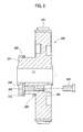
- Fig. 6 is a cross-sectional view of a wire-rope holder of the ultrasonic probe shown in Fig. 5 .
- Figs. 7 and 8 are perspective views of a transducer of the ultrasonic probe shown in Fig. 5 .
- Fig. 9 is a cross-sectional view of an ultrasonic probe for three-dimensional imaging, which is constructed in accordance with an embodiment of the present invention.
- the device 200 for rotating a transducer of an ultrasonic probe includes the following: a drive motor 210 having a drive shaft; a drive pulley 220 coupled to the drive shaft of the drive motor 210; a driven pulley 240 driven by the drive pulley 220; a belt 230 transmitting a drive force from the drive pulley 220 to the driven pulley 240; and a transducer 270 connected to the driven pulley 240 via a pair of wire-ropes 260.
- a tension of the wire-rope 260 produced by the rotation of the driven pulley 240 can rotate the transducer 270.
- the drive motor 210 is a step motor.
- a wire-rope holder 241 is formed on the driven pulley 240 concentrically, with one end of a wire-rope 260 being fixed to the wire-rope holder 241.
- the wire-rope 260 is wound around the wire-rope holder 241.
- a via hole 242 is formed on the wire-rope holder 241 from the periphery to the center.
- a screw hole 243 is formed on the driven pulley 240 orthogonal to the via hole 242.
- the screw hole 241 communicates a surface of the driven pulley 240 and the via hole 242.
- wire-rope 260 is fixed to the wire-rope holder 240 such that one end of the wire-rope 260 is inserted to the via hole 242.
- the wire-rope is wound around the wire-rope holder 241.
- a screw 245 is fastened in the screw hole 243 to press the wire-rope 260 inserted in the via hole 242.
- a pressing member 244 can be provided in the screw hole. The pressing member 244 is pressed by the screw 245, while the pressing member 244 presses the wire-rope 260 in the via hole 242.
- the pressing member 244 has a larger cross-sectional area and a smaller hardness than the screw 245 for protecting the wire-rope 260.
- the transducer 270 includes: ultrasonic elements 271; a transducer holder 272 having a rotating shaft 275; a pair of wire-rope guides 273 mounted on both sides of the transducer 272 for arranging wire ropes 260 along the both sides of the transducer 270; a pair of wire-rope holes 274 formed through the transducer 270 parallel to the rotating shaft 275; and a pair of buffer springs 276 mounted on both sides of the transducer 270. Both buffer springs 276 are facial to each other around the transducer. Both wire-rope guides 273 are provided at both sides of the transducer 270. A via hole communicates an end of a wire-rope guide 273 and a corresponding buffer spring 276.
- wire-rope 260 is fixed to the wire rope holder 240 and the other end thereof is fixed to one of the buffer springs 270 via the wire-rope guide 273 and the wire-rope hole 274.
- the wire ropes 260 are connected to the corresponding buffer springs 276.
- a pair of pin guides 277 having a cylindrical cross-section are formed adjacent to the end of the wire-rope holes 274. This is so that the edges of the wire-rope holes 274 do not contact the wire-ropes 260.
- pin guides 277 are formed on the wire-rope guides 273.
- the pin guides 277 can be formed adjacent to the buffer spring 276. Bearings, pulleys or the like, which can reduce the friction force between the wire rope 260 and the edge of the wire-rope hole 274, can be used instead of the pin guides 277.
- a driving force of the drive motor 210 rotates the drive pulley 220, while the belt 230 rotates the driven pulley 240.
- the rotation of the driven pulley 240 pulls one of a pair of wire-ropes 260.
- the drive force is converted into a tension of the wire-rope 260.
- the tension of the wire-rope 260 is transmitted to the buffer spring 276 via the wire-rope guide 273 and the wire-rope hole 274.
- the tension makes the rotating momentum of the transducer around the rotating shaft 275, thereby rotating the transducer 270.
- the buffer spring 276 absorbs a shock produced while the tension of the wire-rope 260 is transmitted to the transducer 270.
- the driven pulley 240 pulls the other wire-rope 260.
- the transducer 270 rotates reversely in the similar process to that mentioned above.
- the ultrasonic probe can be manufactured with a compact size, thereby removing the space occupied by the driven shaft disposed across the case 201.
- the spare area can be used for additional terminals for additional ultrasonic elements. Additional ultrasonic elements can improve the quality of a three-dimensional image obtained.
- the structure of the wire-rope holder 241 is not so complex to manufacture.
- the buffer spring 276 can remove the buffering means of the wire-rope holder 241. As such, the manufacturing process can be simple and the productivity of an ultrasonic probe can be increased.
- Embodiments of the present invention may provide a device for rotating a transducer of an ultrasonic probe.
- the device may comprise: a drive motor; a pulley rotatably driven by the drive motor; a pair of wire-ropes wounded around the pulley; a rotatable transducer having a plurality of ultrasonic elements; and a pair of buffer springs each connecting one end of the respective wire-rope and the transducer, wherein the buffer springs are attached to the transducer.
- the pulley can include: a wire-rope holder protruded from the pulley concentrically, the wire rope being wound around the wire-rope holder; a via hole formed from the periphery to the center of the wire-rope holder for inserting one end of each wire-rope thereto; a screw hole formed from a surface of the pulley to the via hole; and a screw fastened in the screw holes for fixing the wire-rope inserted in the via hole.
- a pressing member can be interposed between the wire-rope and the screw in the screw hole, wherein the pressing member has a larger cross-sectional area than the screw.
- the transducer can include a pair of wire-rope guides mounted to both sides of the transducer for guiding the wire-ropes.
- the buffer springs can be mounted to the opposite side of the wire-rope guides on the transducer.
- a pair of wire-rope holes can be formed through the transducer for communicating each wire-rope guide and the corresponding buffer spring.
- Pin guides having a cylindrical cross-section can be formed adjacent to one ends of the wire-rope holes.
- any reference in this specification to "one embodiment,” “an embodiment,” “example embodiment,” etc. means that a particular feature, structure or characteristic described in connection with the embodiment is included in at least one embodiment of the present invention.
- the appearances of such phrases in various places in the specification are not necessarily all referring to the same embodiment.
Landscapes
- Health & Medical Sciences (AREA)
- Life Sciences & Earth Sciences (AREA)
- Engineering & Computer Science (AREA)
- Physics & Mathematics (AREA)
- Surgery (AREA)
- Public Health (AREA)
- Radiology & Medical Imaging (AREA)
- Nuclear Medicine, Radiotherapy & Molecular Imaging (AREA)
- Biomedical Technology (AREA)
- Heart & Thoracic Surgery (AREA)
- Medical Informatics (AREA)
- Molecular Biology (AREA)
- Biophysics (AREA)
- Animal Behavior & Ethology (AREA)
- General Health & Medical Sciences (AREA)
- Pathology (AREA)
- Veterinary Medicine (AREA)
- Radar, Positioning & Navigation (AREA)
- Remote Sensing (AREA)
- Acoustics & Sound (AREA)
- Power Engineering (AREA)
- Computer Networks & Wireless Communication (AREA)
- General Physics & Mathematics (AREA)
- Multimedia (AREA)
- Gynecology & Obstetrics (AREA)
- Ultra Sonic Daignosis Equipment (AREA)
Applications Claiming Priority (1)
| Application Number | Priority Date | Filing Date | Title |
|---|---|---|---|
| KR1020060135164A KR100949061B1 (ko) | 2006-12-27 | 2006-12-27 | 초음파 진단장치의 프로브의 초음파 진동자 회동장치 |
Publications (2)
| Publication Number | Publication Date |
|---|---|
| EP1938755A2 true EP1938755A2 (de) | 2008-07-02 |
| EP1938755A3 EP1938755A3 (de) | 2015-10-14 |
Family
ID=39283163
Family Applications (1)
| Application Number | Title | Priority Date | Filing Date |
|---|---|---|---|
| EP07025146.7A Withdrawn EP1938755A3 (de) | 2006-12-27 | 2007-12-27 | Vorrichtung zum Drehen eines Wandlers einer Ultraschallsonde |
Country Status (3)
| Country | Link |
|---|---|
| US (1) | US7998077B2 (de) |
| EP (1) | EP1938755A3 (de) |
| KR (1) | KR100949061B1 (de) |
Cited By (1)
| Publication number | Priority date | Publication date | Assignee | Title |
|---|---|---|---|---|
| CN103690190A (zh) * | 2012-09-27 | 2014-04-02 | 深圳市索诺瑞科技有限公司 | 机械扫描探头 |
Families Citing this family (10)
| Publication number | Priority date | Publication date | Assignee | Title |
|---|---|---|---|---|
| KR100951589B1 (ko) * | 2007-01-03 | 2010-04-13 | 주식회사 메디슨 | 탐촉부 회동장치의 와이어로프 고정장치를 갖는 초음파 프루브 |
| CN102018531B (zh) * | 2009-09-21 | 2014-03-05 | 深圳迈瑞生物医疗电子股份有限公司 | 一种用于超声成像的探头 |
| CN102087122B (zh) | 2009-12-02 | 2014-10-29 | 深圳迈瑞生物医疗电子股份有限公司 | 一种3d机械探头 |
| KR101116405B1 (ko) * | 2011-02-21 | 2012-03-12 | (주)프로소닉 | 직립 모터 구동 방식의 초음파 프로브 |
| US20130172751A1 (en) * | 2012-01-02 | 2013-07-04 | General Electric Company | Systems and methods for shock absorbing in ultrasound probes |
| CN104235296B (zh) * | 2013-06-19 | 2017-01-25 | 深圳迈瑞生物医疗电子股份有限公司 | 探头传动装置 |
| CN104224228B (zh) * | 2013-06-19 | 2017-08-11 | 深圳迈瑞生物医疗电子股份有限公司 | 3d机械探头及绳索传动装置 |
| CN104948687B (zh) * | 2015-05-07 | 2019-03-19 | 东方晶源微电子科技(北京)有限公司 | 一种适用于光机检测系统的带传动机构 |
| CN104948690B (zh) * | 2015-05-07 | 2019-02-01 | 东方晶源微电子科技(北京)有限公司 | 一种具有张力保持装置的滑轮 |
| CN115523270B (zh) * | 2022-10-26 | 2025-09-23 | 武汉联影医疗科技有限公司 | 绳索传动装置、超声波探头及超声波设备 |
Citations (1)
| Publication number | Priority date | Publication date | Assignee | Title |
|---|---|---|---|---|
| KR20060076026A (ko) | 2004-12-29 | 2006-07-04 | 주식회사 메디슨 | 초음파 진단장치의 프로브의 초음파 진동자 회동장치 |
Family Cites Families (10)
| Publication number | Priority date | Publication date | Assignee | Title |
|---|---|---|---|---|
| US4203324A (en) * | 1977-08-05 | 1980-05-20 | Joseph Baumoel | Sonic liquid level detector |
| US4485462A (en) * | 1982-09-29 | 1984-11-27 | Honeywell Elac-Nautik Gmbh | Transducer mounting apparatus |
| JPH0255050A (ja) * | 1988-08-22 | 1990-02-23 | Toshiba Corp | 機械式走査型超音波探触子 |
| IL87648A0 (en) | 1988-09-01 | 1989-02-28 | Elscint Ltd | Ultrasonic probe |
| US5351692A (en) * | 1993-06-09 | 1994-10-04 | Capistrano Labs Inc. | Laparoscopic ultrasonic probe |
| AU4159097A (en) | 1996-08-30 | 1998-03-19 | Whitaker Corporation, The | Apparatus to flex a bendable probe |
| JP3490390B2 (ja) * | 2000-11-17 | 2004-01-26 | 松下電器産業株式会社 | 超音波探触子およびその製造方法 |
| JP3664710B2 (ja) * | 2002-12-24 | 2005-06-29 | 松下電器産業株式会社 | 超音波探触子 |
| US7105956B2 (en) | 2004-04-23 | 2006-09-12 | Aerotech, Inc. | High precision z-theta stage |
| KR100747094B1 (ko) | 2005-07-15 | 2007-08-07 | 주식회사 메디슨 | 초음파 프루브의 트랜스듀서 구동장치 |
-
2006
- 2006-12-27 KR KR1020060135164A patent/KR100949061B1/ko not_active Expired - Fee Related
-
2007
- 2007-12-27 EP EP07025146.7A patent/EP1938755A3/de not_active Withdrawn
- 2007-12-27 US US11/964,876 patent/US7998077B2/en not_active Expired - Fee Related
Patent Citations (1)
| Publication number | Priority date | Publication date | Assignee | Title |
|---|---|---|---|---|
| KR20060076026A (ko) | 2004-12-29 | 2006-07-04 | 주식회사 메디슨 | 초음파 진단장치의 프로브의 초음파 진동자 회동장치 |
Cited By (2)
| Publication number | Priority date | Publication date | Assignee | Title |
|---|---|---|---|---|
| CN103690190A (zh) * | 2012-09-27 | 2014-04-02 | 深圳市索诺瑞科技有限公司 | 机械扫描探头 |
| CN103690190B (zh) * | 2012-09-27 | 2015-09-02 | 深圳市索诺瑞科技有限公司 | 机械扫描探头 |
Also Published As
| Publication number | Publication date |
|---|---|
| KR20080060728A (ko) | 2008-07-02 |
| US7998077B2 (en) | 2011-08-16 |
| KR100949061B1 (ko) | 2010-03-25 |
| US20080161694A1 (en) | 2008-07-03 |
| EP1938755A3 (de) | 2015-10-14 |
Similar Documents
| Publication | Publication Date | Title |
|---|---|---|
| US7998077B2 (en) | Device for rotating a transducer of an ultrasonic probe | |
| US7998078B2 (en) | Ultrasonic probe having a device for coupling a wire-rope to a transducer | |
| US7635335B2 (en) | Device for moving a transducer of an ultrasonic probe | |
| EP2309929B1 (de) | Ultraschallsonde für dreidimensionale bildgebung | |
| KR100741694B1 (ko) | 초음파 진단장치의 프로브의 초음파 진동자 회동장치 | |
| WO2015056823A1 (ko) | 진동 발생 기능을 갖는 초음파 프로브 및 이를 포함하는 초음파 진단장치 | |
| EP1938753A1 (de) | Vorrichtung zum Drehen eines Wandlers einer Ultraschallsonde | |
| KR102255420B1 (ko) | 3d 초음파 프로브 | |
| WO2012115354A2 (ko) | 직립 모터 구동 방식의 초음파 프로브 | |
| KR100891287B1 (ko) | 초음파 진단장치의 프루브 | |
| JP3852183B2 (ja) | 超音波プローブ | |
| KR100992445B1 (ko) | 초음파 진단장치 | |
| CN115523270B (zh) | 绳索传动装置、超声波探头及超声波设备 | |
| JP3852296B2 (ja) | 超音波プローブ | |
| CN223262961U (zh) | 一种腔内探头及超声设备 | |
| CN219461255U (zh) | 控制装置及缝合组件 | |
| KR20070029891A (ko) | 초음파 프루브 및 초음파 소자 유닛 구동 장치 | |
| KR20080016021A (ko) | 초음파 프로브 | |
| JP3671725B2 (ja) | 超音波プローブ | |
| CN118319359A (zh) | 超声探头及医疗器械 | |
| KR101271847B1 (ko) | 초음파프로브 | |
| CN121445416A (zh) | 一种腔内超声探头 | |
| JP4405762B2 (ja) | 超音波探触子およびその超音波撮影装置とそのブッシング | |
| CN119074041A (zh) | 超声探头及超声成像装置 | |
| JP2008188175A (ja) | 超音波診断装置 |
Legal Events
| Date | Code | Title | Description |
|---|---|---|---|
| PUAI | Public reference made under article 153(3) epc to a published international application that has entered the european phase |
Free format text: ORIGINAL CODE: 0009012 |
|
| AK | Designated contracting states |
Kind code of ref document: A2 Designated state(s): AT BE BG CH CY CZ DE DK EE ES FI FR GB GR HU IE IS IT LI LT LU LV MC MT NL PL PT RO SE SI SK TR |
|
| AX | Request for extension of the european patent |
Extension state: AL BA HR MK RS |
|
| PUAL | Search report despatched |
Free format text: ORIGINAL CODE: 0009013 |
|
| AK | Designated contracting states |
Kind code of ref document: A3 Designated state(s): AT BE BG CH CY CZ DE DK EE ES FI FR GB GR HU IE IS IT LI LT LU LV MC MT NL PL PT RO SE SI SK TR |
|
| AX | Request for extension of the european patent |
Extension state: AL BA HR MK RS |
|
| RIC1 | Information provided on ipc code assigned before grant |
Ipc: G01S 15/89 20060101ALI20150910BHEP Ipc: H02K 7/00 20060101ALI20150910BHEP Ipc: F16H 19/00 20060101ALI20150910BHEP Ipc: G10K 11/35 20060101ALI20150910BHEP Ipc: A61B 8/08 20060101AFI20150910BHEP |
|
| AKY | No designation fees paid | ||
| AXX | Extension fees paid |
Extension state: HR Extension state: AL Extension state: RS Extension state: MK Extension state: BA |
|
| REG | Reference to a national code |
Ref country code: DE Ref legal event code: R108 |
|
| STAA | Information on the status of an ep patent application or granted ep patent |
Free format text: STATUS: THE APPLICATION IS DEEMED TO BE WITHDRAWN |
|
| 18D | Application deemed to be withdrawn |
Effective date: 20160415 |