EP1938885B1 - Filteranlage zum Abscheiden von Stäuben aus Gasen - Google Patents
Filteranlage zum Abscheiden von Stäuben aus Gasen Download PDFInfo
- Publication number
- EP1938885B1 EP1938885B1 EP07024051A EP07024051A EP1938885B1 EP 1938885 B1 EP1938885 B1 EP 1938885B1 EP 07024051 A EP07024051 A EP 07024051A EP 07024051 A EP07024051 A EP 07024051A EP 1938885 B1 EP1938885 B1 EP 1938885B1
- Authority
- EP
- European Patent Office
- Prior art keywords
- filter
- collecting
- line
- gases
- filter unit
- Prior art date
- Legal status (The legal status is an assumption and is not a legal conclusion. Google has not performed a legal analysis and makes no representation as to the accuracy of the status listed.)
- Not-in-force
Links
- 239000000428 dust Substances 0.000 title claims description 18
- 239000007789 gas Substances 0.000 title claims description 18
- 239000002245 particle Substances 0.000 title description 2
- 239000012065 filter cake Substances 0.000 claims description 6
- 238000004140 cleaning Methods 0.000 claims description 3
- 238000001914 filtration Methods 0.000 claims description 3
- 238000007664 blowing Methods 0.000 claims 1
- 238000000605 extraction Methods 0.000 claims 1
- 230000000694 effects Effects 0.000 description 1
- 238000000034 method Methods 0.000 description 1
- 238000000926 separation method Methods 0.000 description 1
Images
Classifications
-
- B—PERFORMING OPERATIONS; TRANSPORTING
- B01—PHYSICAL OR CHEMICAL PROCESSES OR APPARATUS IN GENERAL
- B01D—SEPARATION
- B01D46/00—Filters or filtering processes specially modified for separating dispersed particles from gases or vapours
- B01D46/42—Auxiliary equipment or operation thereof
- B01D46/48—Removing dust other than cleaning filters, e.g. by using collecting trays
Definitions
- the invention relates to a filter system for separating dusts from gases according to the preamble of patent claim 1.
- filter systems have a plurality of filter units which are connected in parallel to a line for raw gas and to a line for clean gas.
- Each filter unit usually contains a plurality of so-called filter cartridges, which are successively flowed through by the raw gas stream, wherein the flow direction is usually from bottom to top.
- the separated dust particles deposit on the filter and form a filter cake.
- the flow resistance of the filter cartridge increases. If a certain differential pressure is exceeded, a cleaning of the filter cassette takes place automatically, for example on pneumatic Ways. The cleaned filter cake is collected in a collecting space below the filter cassettes and then removed from the filter system.
- the invention has for its object to provide a filter system for the separation of dusts from gases, with a similar effect as in the last-described central dust collector is achieved, however, a significantly reduced operational effort must be made available.
- the dust discharge openings of all filter units are connected to one with a common manifold.
- the collecting line is connected to the raw gas region of a filter unit.
- the manifold is connected to the plenum of the one filter unit.
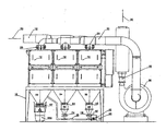
- the single figure shows schematically a filter system according to the invention in side view.
- a first line 18 is connected via connections 20 to the upper end of the filter units 10 to 14.
- the line 18 is a so-called raw gas line. It is charged according to arrow 20 with a source of raw gas, ie dust-laden gas.
- a clean gas line 22 is connected via corresponding connections 24 to the output of the filter units 10 to 14.
- the clean gas line 22 is connected to the inlet of a blower 26 whose output 28 goes to the atmosphere, as indicated at 30.
- a funnel 32, 34, 36 is arranged at the lower end of each filter unit 10 to 14.
- Each hopper 32, 34, 36 has a dust outlet opening, which can be closed by a flap 52, 54, 56.
- a dust collector 64, 66 which receives the resulting dusts during filtration and the filter cleaning process.
- a second flap 74, 76 may be provided, which establishes the connection to the manifold 38 and during the open position of the flap 54, 56 closes the passage to the manifold 38.
- the manifold 38 connects the dust collector 64, 66 and their dust outlet with each other.
- the one end of the manifold 38 is connected to the hopper 32 of the filter unit 10. Below the filter unit 10 and the funnel 32, a collecting vessel 38 a is arranged.
- the collecting space 32 is therefore a central collecting space for all filter units 10 to 14 whose dust or filter cake is collected in the vessel 38. This happens because there is a negative pressure in the collecting chamber 32 during operation of the filter systems.
- a channel is directed down to the lowermost filter cassette.
- the negative pressure which causes a flow through the filter cartridges, also in the collecting space 32.
- the dust from the other collecting chambers 34, 36 is sucked and conveyed into the collecting space 36.
- the bus 38 must be open at the other end.
- a valve 40 operable by a servo actuator 42 is connected to atmosphere through a filter 44. The valve 40 is opened when dust from the collecting chambers 34, 36 is to be conveyed into the collecting space 32.
Landscapes
- Chemical & Material Sciences (AREA)
- Chemical Kinetics & Catalysis (AREA)
- Filtering Of Dispersed Particles In Gases (AREA)
- Processes For Solid Components From Exhaust (AREA)
Description
- Die Erfindung bezieht sich auf eine Filteranlage zum Abscheiden von Stäuben aus Gasen nach dem Oberbegriff des Patentanspruchs 1.
- Es ist bekannt, daß derartige Filteranlagen eine Vielzahl von Filtereinheiten aufweisen, die parallel an eine Leitung für Rohgas und an eine Leitung für Reingas angeschlossen sind. Jede Filtereinheit enthält zumeist eine Mehrzahl von sogenannten Filterkassetten, die nacheinander vom Rohgasstrom durchströmt sind, wobei die Strömungsrichtung üblicherweise von unten nach oben erfolgt. Die abgeschiedenen Staubpartikel lagern sich am Filter ab und bilden einen Filterkuchen. Durch Anwachsen des Filterkuchens steigt der Strömungswiderstand der Filterkassette. Wird darin ein bestimmter Differenzdruck überschritten, findet automatisch eine Reinigung der Filterkassette statt, beispielsweise auf pneumatischem Wege. Der abgereinigte Filterkuchen wird in einem Sammelraum unterhalb der Filterkassetten aufgefangen und anschließend aus der Filteranlage entnommen.
- Es ist bekannt, unterhalb jedes Sammelraums einer Filtereinheit ein Sammelgefäß aufzustellen, in das der abgereinigte Filterkuchen abgefüllt wird. Eine derartige Handhabung ist verhältnismäßig aufwendig, da für jede Filtereinheit ein Sammelgefäß vorgesehen werden muß, das von Zeit zu Zeit gegen ein leeres auszuwechseln ist.
- Es ist jedoch auch bekannt, wie aus Dokument
WO 9 007 369 - Der Erfindung liegt die Aufgabe zugrunde, eine Filteranlage zum Abscheiden von Stäuben aus Gasen zu schaffen, mit der eine ähnliche Wirkung wie bei dem zuletzt beschriebenen zentralen Staubsammler erzielt wird, wobei jedoch ein deutlich verringerter operativer Aufwand zur Verfügung gestellt werden muß.
- Diese Aufgabe wird durch die Merkmale des Patentanspruchs 1 gelöst.
- Bei der erfindungsgemäßen Filteranlage sind die Staubaustragöffnungen aller Filtereinheiten bis auf eine mit einer gemeinsamen Sammelleitung verbunden. Die Sammelleitung ist mit dem Rohgasbereich der einen Filtereinheit verbunden. Vorzugsweise ist die Sammelleitung mit dem Sammelraum der einen Filtereinheit verbunden.
- Bei der Erfindung wird von der Kenntnis ausgegangen, daß im Rohgasbereich jeder Filtereinheit ein Unterdruck herrscht. Diesen Unterdruck benutzt die erfindungsgemäße Filteranlage, um Staub aus den Sammelräumen der anderen Filteranlagen in den Sammelraum der einen Filtereinheit zu transportieren. Somit ist die eine Filtereinheit mit einem zentralen Staubsammelraum ausgerüstet.
- Ein Ausführungsbeispiel der Erfindung wird nachfolgend anhand einer Zeichnung näher erläutert:
- Die einzige Figur zeigt schematisch eine Filteranlage nach der Erfindung in Seitenansicht.
- In der in der Figur gezeigten Filteranlage sind drei Filtereinheiten 10, 12 und 14 nebeneinander angeordnet. Sie stehen auf einem gemeinsamen Gestell 16. Eine erste Leitung 18 ist über Anschlüsse 20 mit dem oberen Ende der Filtereinheiten 10 bis 14 verbunden. Die Leitung 18 ist eine sogenannte Rohgasleitung. Sie wird gemäß Pfeil 20 mit einer Quelle für Rohgas, d.h. staubbelastetes Gas, beschickt. Eine Reingasleitung 22 ist über entsprechende Anschlüsse 24 mit dem Ausgang der Filtereinheiten 10 bis 14 verbunden. Die Reingasleitung 22 ist mit dem Eingang eines Gebläses 26 verbunden, dessen Ausgang 28 zur Atmosphäre geht, wie bei 30 angedeutet. Am unteren Ende jeder Filtereinheit 10 bis 14 ist ein Trichter 32, 34, 36 angeordnet. Jeder Trichter 32, 34, 36 hat eine Staubaustrittsöffnung, die durch eine Klappe 52, 54, 56 verschlossen werden kann. Unterhalb der Klappe 54, 56 befindet sich ein Staubsammler 64, 66, der die anfallenden Stäube während der Filtration und des Filterreinigungsprozesses aufnimmt. Optional kann unterhalb der Staubsammler 64, 66 eine zweite Klappe 74, 76 vorgesehen sein, die die Verbindung zur Sammelleitung 38 herstellt und während der geöffneten Position der Klappe 54, 56 den Durchgang zur Sammelleitung 38 verschließt. Die Sammelleitung 38 verbindet die Staubsammler 64, 66 bzw. deren Staubaustrittsöffnung miteinander.
- Das eine Ende der Sammelleitung 38 ist mit dem Trichter 32 der Filtereinheit 10 verbunden. Unterhalb der Filtereinheit 10 bzw. des Trichters 32 ist ein Auffanggefäß 38a angeordnet. Der Sammelraum 32 ist mithin zentraler Sammelraum für alle Filtereinheiten 10 bis 14, deren Staub bzw. Filterkuchen im Gefäß 38 aufgefangen wird. Dies geschieht dadurch, daß im Sammelraum 32 ein Unterdruck im Betrieb der Filteranlagen herrscht. Üblicherweise wird bei derartigen Filtereinheiten 10-14, an die der Eingang des Gebläses 26 angeschlossen ist, ein Kanal nach unten zur untersten Filterkassette geleitet. Damit herrscht der Unterdruck, der eine Strömung durch die Filterkassetten bewirkt, auch im Sammelraum 32. Dadurch wird der Staub aus den anderen Sammelräumen 34, 36 angesaugt und in den Sammelraum 36 gefördert. Zu diesem Zweck muß jedoch die Sammelleitung 38 am anderen Ende offen sein. Ein Ventil 40, das von einer Servobetätigung 42 betätigbar ist, ist über einen Filter 44 mit Atmosphäre verbunden. Das Ventil 40 wird geöffnet, wenn Staub aus den Sammelräumen 34, 36 in den Sammelraum 32 gefördert werden soll.
Claims (2)
- Filteranlage zur Abscheidung von Stäuben aus Gasen, mit einer Mehrzahl von Filtereinheiten (10, 12, 14), die parallel an eine Leitung für Rohgas und deren Ausgänge parallel an eine Leitung für Reingas angeschlossen sind, wobei an die Leitung für Reingas ein. Sauggebläse angeschlossen ist, ferner mit einer Vorrichtung zum Reinigen der Filtereinheiten, wobei jede Filtereinheit einen unteren Sammelraum (32, 34, 36) für den Filterkuchen aufweist mit einer Austragöffnung mit Verschluß am unteren Ende des Sammelraums, dadurch gekenntzeichnet, daß die Staubaustragöffnung aller Filtereinheiten (12, 14) bis auf eine bestimmte (10) mit einer gemeinsamen Sammelleitung (38) verbunden sind und die Sammelleitung (38) mit dem Rohgasbereich der bestimmten Filtereinheit (10) verbunden ist.
- Filteranlage nach Anspruch 1, dadurch gekennzeichnet, daß die Sammelleitung (38) mit dem Sammelraum (32) der bestimmten Filtereinheit (10) verbunden ist.
Applications Claiming Priority (1)
| Application Number | Priority Date | Filing Date | Title |
|---|---|---|---|
| DE102006061256A DE102006061256B4 (de) | 2006-12-22 | 2006-12-22 | Filteranlage zum Abscheiden von Stäuben aus Gasen |
Publications (2)
| Publication Number | Publication Date |
|---|---|
| EP1938885A1 EP1938885A1 (de) | 2008-07-02 |
| EP1938885B1 true EP1938885B1 (de) | 2010-07-21 |
Family
ID=39295589
Family Applications (1)
| Application Number | Title | Priority Date | Filing Date |
|---|---|---|---|
| EP07024051A Not-in-force EP1938885B1 (de) | 2006-12-22 | 2007-12-12 | Filteranlage zum Abscheiden von Stäuben aus Gasen |
Country Status (3)
| Country | Link |
|---|---|
| US (1) | US7951215B2 (de) |
| EP (1) | EP1938885B1 (de) |
| DE (2) | DE102006061256B4 (de) |
Families Citing this family (3)
| Publication number | Priority date | Publication date | Assignee | Title |
|---|---|---|---|---|
| DE202012013036U1 (de) * | 2012-03-09 | 2014-08-04 | Cl Schutzrechtsverwaltungs Gmbh | Filtereinrichtung zum Anschluss an eine Lasersinter- oder Laserschmelzanlage |
| CL2012002186A1 (es) * | 2012-08-03 | 2012-10-05 | Inovaciony Desarrollo Tecnologico S A | Sistema de captación y extracción de gases y particulas contaminantes que son partes de un circuito cerado de vapor a presion, incluyendo dos estacionaes de recuperacion de gases cilindricas conectadas a una campana de extraccion, un ventilador de tiro inducido y un precipitador dinamico de agua. |
| EP4049831A1 (de) | 2017-07-21 | 2022-08-31 | CL Schutzrechtsverwaltungs GmbH | Vorrichtung zur generativen fertigung dreidimensionaler objekte |
Family Cites Families (18)
| Publication number | Priority date | Publication date | Assignee | Title |
|---|---|---|---|---|
| US2892512A (en) * | 1957-08-16 | 1959-06-30 | Standard Oil Co | Flow limiting filter valve |
| US3146080A (en) * | 1960-08-01 | 1964-08-25 | Continental Carbon Co | Carbon black collecting process |
| GB1145827A (en) * | 1965-07-22 | 1969-03-19 | Smidth & Co As F L | Treatment of dust from cement kilns |
| US3491518A (en) * | 1966-09-15 | 1970-01-27 | Ashland Oil Inc | Solid-gas separating means |
| DE1607694C3 (de) * | 1967-02-11 | 1974-08-29 | Deutsche Gold- Und Silber-Scheideanstalt Vormals Roessler, 6000 Frankfurt | Anlage zur Abscheidung von Feststoffen aus Aerosolen |
| GB1481697A (en) * | 1974-04-10 | 1977-08-03 | British Steel Corp | Bag filter installation |
| FR2432883A1 (fr) * | 1978-08-11 | 1980-03-07 | Commissariat Energie Atomique | Dispositif de separation et de recuperation d'un produit solide transporte par un gaz |
| US4205931A (en) * | 1978-12-04 | 1980-06-03 | Combustion Engineering, Inc. | Pneumatic ash transporting and containing system |
| US4523933A (en) * | 1980-08-29 | 1985-06-18 | Scott Paper Company | Apparatus for conveying particulate material |
| US4446109A (en) * | 1980-09-22 | 1984-05-01 | Peabody Process Systems, Inc. | System for dry scrubbing of flue gas |
| DE3420972A1 (de) * | 1984-06-06 | 1985-12-12 | Bühler-Miag GmbH, 3300 Braunschweig | Anordnung zum abziehen von gut bei einer filteranlage |
| DE3505729A1 (de) * | 1985-02-15 | 1986-08-21 | Deutsche Filterbau GmbH, 4000 Düsseldorf | Verfahren zur reinigung von filterelementen |
| US4759781A (en) * | 1987-03-09 | 1988-07-26 | Olson Robert P | Filtering and dust collecting apparatus |
| ATE112504T1 (de) * | 1989-01-03 | 1994-10-15 | Future Air Tech | Staubsammelsystem mit off-line-filterreinigung. |
| FR2664178B1 (fr) * | 1990-07-09 | 1992-10-30 | Gore W L & Ass Sarl | Installation de filtrage de gaz a moyens de decolmatage perfectionnes. |
| DE9203474U1 (de) * | 1992-03-16 | 1992-09-24 | Obermüller, Herbert, 6464 Linsengericht | Schwebstoff-Filteranlage |
| DE19652160B4 (de) * | 1996-12-14 | 2004-01-29 | British-American Tobacco (Germany) Gmbh | Entstaubungsanlage |
| DE102004024713A1 (de) * | 2004-05-19 | 2005-12-15 | Melitta Haushaltsprodukte Gmbh & Co. Kg | Mahlvorrichtung für Kaffeebohnen |
-
2006
- 2006-12-22 DE DE102006061256A patent/DE102006061256B4/de not_active Expired - Fee Related
-
2007
- 2007-12-12 DE DE502007004472T patent/DE502007004472D1/de active Active
- 2007-12-12 EP EP07024051A patent/EP1938885B1/de not_active Not-in-force
- 2007-12-20 US US11/960,980 patent/US7951215B2/en not_active Expired - Fee Related
Also Published As
| Publication number | Publication date |
|---|---|
| US20080223009A1 (en) | 2008-09-18 |
| EP1938885A1 (de) | 2008-07-02 |
| DE102006061256B4 (de) | 2009-04-30 |
| US7951215B2 (en) | 2011-05-31 |
| DE102006061256A1 (de) | 2008-06-26 |
| DE502007004472D1 (de) | 2010-09-02 |
Similar Documents
| Publication | Publication Date | Title |
|---|---|---|
| DE69715560T2 (de) | Zyklon-Staubsammelvorrichtung | |
| EP1024878B1 (de) | Verfahren und vorrichtung zum reinigen eines staubabscheiders | |
| EP4065252B1 (de) | Verfahren zur intermittierenden abreinigung eines filters sowie filtereinrichtung für eine metall-druckeinrichtung | |
| DE102009005158A1 (de) | Kombinationsfilter | |
| DE3422093C2 (de) | Entstaubungsvorrichtung | |
| DE903890C (de) | Mehrkammer-Filteranlage | |
| DE102007011246A1 (de) | Druckluftversorgungseinrichtung und Ventilgehäuse | |
| DE102004036083B4 (de) | Ansaugvorrichtung | |
| EP1938885B1 (de) | Filteranlage zum Abscheiden von Stäuben aus Gasen | |
| DE925392C (de) | Mehrkammer-Staubfilteranlage | |
| DE19722840B4 (de) | Vorrichtung zur Regeneration von Speicherfiltern | |
| DE2540672C3 (de) | Für pneumatische Saugförderanlagen vorgesehener Abscheider, insbesondere zum Beschicken von kunststoffverarbeitenden Maschinen | |
| EP3453444A1 (de) | Vorrichtung zur feststoffabscheidung aus gasen | |
| DE202006016366U1 (de) | Für einen Staubsauger bestimmte Einrichtung zum Abtrennen und Sammeln von Schmutz | |
| DE10126048B4 (de) | Vorrichtung zum Reinigen staubbeladener Rohgase | |
| EP1563889B1 (de) | Filternder Abscheider für partikelbelastete Gase | |
| DE102008045613B4 (de) | Anlage zum Aufnehmen, Fördern und Abscheiden von Reststoffen | |
| DE102012207139A1 (de) | Verfahren und Vorrichtung zum Filtern von Partikeln aus Gasen | |
| DE2705040C2 (de) | ||
| DE102024002148A1 (de) | Anlage zum Entfernen von Partikeln, insbesondere Stäuben, aus einem Gasstrom sowie Verfahren zum Entfernen von Partikeln, insbesondere Stäuben, aus einem Gasstrom | |
| DE4330644C1 (de) | Filternder Abscheider | |
| DE1407293A1 (de) | Vorrichtung zum Auffangen und Ausscheiden von Faserflug und Staub im Abluftkanal von Belueftungs- oder Klimaanlagen in Textilbetrieben,insbesondere Spinnereien und Webereien | |
| DE1659961B1 (de) | Abwurfschaechte in Gebaeuden zum Abwurf von Abfaellen,Saecken mit verschmutzter Waesche od.dgl. | |
| WO2021190755A1 (de) | Vorrichtung zum absondern von feststoffpartikeln | |
| EP3730023A1 (de) | Staubsaugvorrichtung mit einem sammelbehälter, in dem unterschiedliche bereiche abgetrennt werden können, sowie verfahren zum auswechseln eines entsorgungsbeutels in einer staubsaugvorrichtung |
Legal Events
| Date | Code | Title | Description |
|---|---|---|---|
| PUAI | Public reference made under article 153(3) epc to a published international application that has entered the european phase |
Free format text: ORIGINAL CODE: 0009012 |
|
| AK | Designated contracting states |
Kind code of ref document: A1 Designated state(s): AT BE BG CH CY CZ DE DK EE ES FI FR GB GR HU IE IS IT LI LT LU LV MC MT NL PL PT RO SE SI SK TR |
|
| AX | Request for extension of the european patent |
Extension state: AL BA HR MK RS |
|
| 17P | Request for examination filed |
Effective date: 20080528 |
|
| AKX | Designation fees paid |
Designated state(s): BE CH DE FR GB IT LI |
|
| GRAP | Despatch of communication of intention to grant a patent |
Free format text: ORIGINAL CODE: EPIDOSNIGR1 |
|
| GRAS | Grant fee paid |
Free format text: ORIGINAL CODE: EPIDOSNIGR3 |
|
| GRAA | (expected) grant |
Free format text: ORIGINAL CODE: 0009210 |
|
| AK | Designated contracting states |
Kind code of ref document: B1 Designated state(s): BE CH DE FR GB IT LI |
|
| REG | Reference to a national code |
Ref country code: GB Ref legal event code: FG4D Free format text: NOT ENGLISH |
|
| REG | Reference to a national code |
Ref country code: CH Ref legal event code: NV Representative=s name: ISLER & PEDRAZZINI AG Ref country code: CH Ref legal event code: EP |
|
| REF | Corresponds to: |
Ref document number: 502007004472 Country of ref document: DE Date of ref document: 20100902 Kind code of ref document: P |
|
| PLBE | No opposition filed within time limit |
Free format text: ORIGINAL CODE: 0009261 |
|
| STAA | Information on the status of an ep patent application or granted ep patent |
Free format text: STATUS: NO OPPOSITION FILED WITHIN TIME LIMIT |
|
| 26N | No opposition filed |
Effective date: 20110426 |
|
| REG | Reference to a national code |
Ref country code: DE Ref legal event code: R081 Ref document number: 502007004472 Country of ref document: DE Owner name: FETTE COMPACTING GMBH, DE Free format text: FORMER OWNER: FETTE GMBH, 21493 SCHWARZENBEK, DE Effective date: 20110621 |
|
| REG | Reference to a national code |
Ref country code: DE Ref legal event code: R097 Ref document number: 502007004472 Country of ref document: DE Effective date: 20110426 |
|
| PG25 | Lapsed in a contracting state [announced via postgrant information from national office to epo] |
Ref country code: IT Free format text: LAPSE BECAUSE OF NON-PAYMENT OF DUE FEES Effective date: 20101212 |
|
| REG | Reference to a national code |
Ref country code: FR Ref legal event code: PLFP Year of fee payment: 9 |
|
| REG | Reference to a national code |
Ref country code: FR Ref legal event code: PLFP Year of fee payment: 10 |
|
| REG | Reference to a national code |
Ref country code: FR Ref legal event code: PLFP Year of fee payment: 11 |
|
| PGFP | Annual fee paid to national office [announced via postgrant information from national office to epo] |
Ref country code: FR Payment date: 20171219 Year of fee payment: 11 |
|
| PGFP | Annual fee paid to national office [announced via postgrant information from national office to epo] |
Ref country code: GB Payment date: 20171221 Year of fee payment: 11 Ref country code: BE Payment date: 20171219 Year of fee payment: 11 Ref country code: CH Payment date: 20171221 Year of fee payment: 11 Ref country code: IT Payment date: 20171218 Year of fee payment: 11 |
|
| PGFP | Annual fee paid to national office [announced via postgrant information from national office to epo] |
Ref country code: DE Payment date: 20180214 Year of fee payment: 11 |
|
| REG | Reference to a national code |
Ref country code: DE Ref legal event code: R119 Ref document number: 502007004472 Country of ref document: DE |
|
| REG | Reference to a national code |
Ref country code: CH Ref legal event code: PL |
|
| REG | Reference to a national code |
Ref country code: DE Ref legal event code: R082 Ref document number: 502007004472 Country of ref document: DE Representative=s name: HAUCK PATENTANWALTSPARTNERSCHAFT MBB, DE |
|
| GBPC | Gb: european patent ceased through non-payment of renewal fee |
Effective date: 20181212 |
|
| REG | Reference to a national code |
Ref country code: BE Ref legal event code: MM Effective date: 20181231 |
|
| PG25 | Lapsed in a contracting state [announced via postgrant information from national office to epo] |
Ref country code: DE Free format text: LAPSE BECAUSE OF NON-PAYMENT OF DUE FEES Effective date: 20190702 Ref country code: FR Free format text: LAPSE BECAUSE OF NON-PAYMENT OF DUE FEES Effective date: 20181231 Ref country code: IT Free format text: LAPSE BECAUSE OF NON-PAYMENT OF DUE FEES Effective date: 20181212 |
|
| PG25 | Lapsed in a contracting state [announced via postgrant information from national office to epo] |
Ref country code: BE Free format text: LAPSE BECAUSE OF NON-PAYMENT OF DUE FEES Effective date: 20181231 |
|
| PG25 | Lapsed in a contracting state [announced via postgrant information from national office to epo] |
Ref country code: GB Free format text: LAPSE BECAUSE OF NON-PAYMENT OF DUE FEES Effective date: 20181212 Ref country code: CH Free format text: LAPSE BECAUSE OF NON-PAYMENT OF DUE FEES Effective date: 20181231 Ref country code: LI Free format text: LAPSE BECAUSE OF NON-PAYMENT OF DUE FEES Effective date: 20181231 |