EP1939059A2 - System zur Moduswechselsteuerung für ein Hybridfahrzeug - Google Patents
System zur Moduswechselsteuerung für ein Hybridfahrzeug Download PDFInfo
- Publication number
- EP1939059A2 EP1939059A2 EP07150202A EP07150202A EP1939059A2 EP 1939059 A2 EP1939059 A2 EP 1939059A2 EP 07150202 A EP07150202 A EP 07150202A EP 07150202 A EP07150202 A EP 07150202A EP 1939059 A2 EP1939059 A2 EP 1939059A2
- Authority
- EP
- European Patent Office
- Prior art keywords
- threshold level
- motor
- generator
- vehicle
- drive mode
- Prior art date
- Legal status (The legal status is an assumption and is not a legal conclusion. Google has not performed a legal analysis and makes no representation as to the accuracy of the status listed.)
- Granted
Links
Images

Classifications
-
- B—PERFORMING OPERATIONS; TRANSPORTING
- B60—VEHICLES IN GENERAL
- B60L—PROPULSION OF ELECTRICALLY-PROPELLED VEHICLES; SUPPLYING ELECTRIC POWER FOR AUXILIARY EQUIPMENT OF ELECTRICALLY-PROPELLED VEHICLES; ELECTRODYNAMIC BRAKE SYSTEMS FOR VEHICLES IN GENERAL; MAGNETIC SUSPENSION OR LEVITATION FOR VEHICLES; MONITORING OPERATING VARIABLES OF ELECTRICALLY-PROPELLED VEHICLES; ELECTRIC SAFETY DEVICES FOR ELECTRICALLY-PROPELLED VEHICLES
- B60L58/00—Methods or circuit arrangements for monitoring or controlling batteries or fuel cells, specially adapted for electric vehicles
- B60L58/10—Methods or circuit arrangements for monitoring or controlling batteries or fuel cells, specially adapted for electric vehicles for monitoring or controlling batteries
- B60L58/12—Methods or circuit arrangements for monitoring or controlling batteries or fuel cells, specially adapted for electric vehicles for monitoring or controlling batteries responding to state of charge [SoC]
-
- B—PERFORMING OPERATIONS; TRANSPORTING
- B60—VEHICLES IN GENERAL
- B60K—ARRANGEMENT OR MOUNTING OF PROPULSION UNITS OR OF TRANSMISSIONS IN VEHICLES; ARRANGEMENT OR MOUNTING OF PLURAL DIVERSE PRIME-MOVERS IN VEHICLES; AUXILIARY DRIVES FOR VEHICLES; INSTRUMENTATION OR DASHBOARDS FOR VEHICLES; ARRANGEMENTS IN CONNECTION WITH COOLING, AIR INTAKE, GAS EXHAUST OR FUEL SUPPLY OF PROPULSION UNITS IN VEHICLES
- B60K6/00—Arrangement or mounting of plural diverse prime-movers for mutual or common propulsion, e.g. hybrid propulsion systems comprising electric motors and internal combustion engines
- B60K6/20—Arrangement or mounting of plural diverse prime-movers for mutual or common propulsion, e.g. hybrid propulsion systems comprising electric motors and internal combustion engines the prime-movers consisting of electric motors and internal combustion engines, e.g. HEVs
- B60K6/42—Arrangement or mounting of plural diverse prime-movers for mutual or common propulsion, e.g. hybrid propulsion systems comprising electric motors and internal combustion engines the prime-movers consisting of electric motors and internal combustion engines, e.g. HEVs characterised by the architecture of the hybrid electric vehicle
- B60K6/48—Parallel type
-
- B—PERFORMING OPERATIONS; TRANSPORTING
- B60—VEHICLES IN GENERAL
- B60L—PROPULSION OF ELECTRICALLY-PROPELLED VEHICLES; SUPPLYING ELECTRIC POWER FOR AUXILIARY EQUIPMENT OF ELECTRICALLY-PROPELLED VEHICLES; ELECTRODYNAMIC BRAKE SYSTEMS FOR VEHICLES IN GENERAL; MAGNETIC SUSPENSION OR LEVITATION FOR VEHICLES; MONITORING OPERATING VARIABLES OF ELECTRICALLY-PROPELLED VEHICLES; ELECTRIC SAFETY DEVICES FOR ELECTRICALLY-PROPELLED VEHICLES
- B60L15/00—Methods, circuits, or devices for controlling the traction-motor speed of electrically-propelled vehicles
- B60L15/20—Methods, circuits, or devices for controlling the traction-motor speed of electrically-propelled vehicles for control of the vehicle or its driving motor to achieve a desired performance, e.g. speed, torque, programmed variation of speed
-
- B—PERFORMING OPERATIONS; TRANSPORTING
- B60—VEHICLES IN GENERAL
- B60L—PROPULSION OF ELECTRICALLY-PROPELLED VEHICLES; SUPPLYING ELECTRIC POWER FOR AUXILIARY EQUIPMENT OF ELECTRICALLY-PROPELLED VEHICLES; ELECTRODYNAMIC BRAKE SYSTEMS FOR VEHICLES IN GENERAL; MAGNETIC SUSPENSION OR LEVITATION FOR VEHICLES; MONITORING OPERATING VARIABLES OF ELECTRICALLY-PROPELLED VEHICLES; ELECTRIC SAFETY DEVICES FOR ELECTRICALLY-PROPELLED VEHICLES
- B60L50/00—Electric propulsion with power supplied within the vehicle
- B60L50/10—Electric propulsion with power supplied within the vehicle using propulsion power supplied by engine-driven generators, e.g. generators driven by combustion engines
- B60L50/16—Electric propulsion with power supplied within the vehicle using propulsion power supplied by engine-driven generators, e.g. generators driven by combustion engines with provision for separate direct mechanical propulsion
-
- B—PERFORMING OPERATIONS; TRANSPORTING
- B60—VEHICLES IN GENERAL
- B60W—CONJOINT CONTROL OF VEHICLE SUB-UNITS OF DIFFERENT TYPE OR DIFFERENT FUNCTION; CONTROL SYSTEMS SPECIALLY ADAPTED FOR HYBRID VEHICLES; ROAD VEHICLE DRIVE CONTROL SYSTEMS FOR PURPOSES NOT RELATED TO THE CONTROL OF A PARTICULAR SUB-UNIT
- B60W10/00—Conjoint control of vehicle sub-units of different type or different function
- B60W10/02—Conjoint control of vehicle sub-units of different type or different function including control of driveline clutches
-
- B—PERFORMING OPERATIONS; TRANSPORTING
- B60—VEHICLES IN GENERAL
- B60W—CONJOINT CONTROL OF VEHICLE SUB-UNITS OF DIFFERENT TYPE OR DIFFERENT FUNCTION; CONTROL SYSTEMS SPECIALLY ADAPTED FOR HYBRID VEHICLES; ROAD VEHICLE DRIVE CONTROL SYSTEMS FOR PURPOSES NOT RELATED TO THE CONTROL OF A PARTICULAR SUB-UNIT
- B60W10/00—Conjoint control of vehicle sub-units of different type or different function
- B60W10/04—Conjoint control of vehicle sub-units of different type or different function including control of propulsion units
- B60W10/06—Conjoint control of vehicle sub-units of different type or different function including control of propulsion units including control of combustion engines
-
- B—PERFORMING OPERATIONS; TRANSPORTING
- B60—VEHICLES IN GENERAL
- B60W—CONJOINT CONTROL OF VEHICLE SUB-UNITS OF DIFFERENT TYPE OR DIFFERENT FUNCTION; CONTROL SYSTEMS SPECIALLY ADAPTED FOR HYBRID VEHICLES; ROAD VEHICLE DRIVE CONTROL SYSTEMS FOR PURPOSES NOT RELATED TO THE CONTROL OF A PARTICULAR SUB-UNIT
- B60W10/00—Conjoint control of vehicle sub-units of different type or different function
- B60W10/04—Conjoint control of vehicle sub-units of different type or different function including control of propulsion units
- B60W10/08—Conjoint control of vehicle sub-units of different type or different function including control of propulsion units including control of electric propulsion units, e.g. motors or generators
-
- B—PERFORMING OPERATIONS; TRANSPORTING
- B60—VEHICLES IN GENERAL
- B60W—CONJOINT CONTROL OF VEHICLE SUB-UNITS OF DIFFERENT TYPE OR DIFFERENT FUNCTION; CONTROL SYSTEMS SPECIALLY ADAPTED FOR HYBRID VEHICLES; ROAD VEHICLE DRIVE CONTROL SYSTEMS FOR PURPOSES NOT RELATED TO THE CONTROL OF A PARTICULAR SUB-UNIT
- B60W20/00—Control systems specially adapted for hybrid vehicles
- B60W20/10—Controlling the power contribution of each of the prime movers to meet required power demand
-
- B—PERFORMING OPERATIONS; TRANSPORTING
- B60—VEHICLES IN GENERAL
- B60W—CONJOINT CONTROL OF VEHICLE SUB-UNITS OF DIFFERENT TYPE OR DIFFERENT FUNCTION; CONTROL SYSTEMS SPECIALLY ADAPTED FOR HYBRID VEHICLES; ROAD VEHICLE DRIVE CONTROL SYSTEMS FOR PURPOSES NOT RELATED TO THE CONTROL OF A PARTICULAR SUB-UNIT
- B60W20/00—Control systems specially adapted for hybrid vehicles
- B60W20/40—Controlling the engagement or disengagement of prime movers, e.g. for transition between prime movers
-
- B—PERFORMING OPERATIONS; TRANSPORTING
- B60—VEHICLES IN GENERAL
- B60W—CONJOINT CONTROL OF VEHICLE SUB-UNITS OF DIFFERENT TYPE OR DIFFERENT FUNCTION; CONTROL SYSTEMS SPECIALLY ADAPTED FOR HYBRID VEHICLES; ROAD VEHICLE DRIVE CONTROL SYSTEMS FOR PURPOSES NOT RELATED TO THE CONTROL OF A PARTICULAR SUB-UNIT
- B60W30/00—Purposes of road vehicle drive control systems not related to the control of a particular sub-unit, e.g. of systems using conjoint control of vehicle sub-units
- B60W30/18—Propelling the vehicle
- B60W30/184—Preventing damage resulting from overload or excessive wear of the driveline
- B60W30/1843—Overheating of driveline components
-
- B—PERFORMING OPERATIONS; TRANSPORTING
- B60—VEHICLES IN GENERAL
- B60W—CONJOINT CONTROL OF VEHICLE SUB-UNITS OF DIFFERENT TYPE OR DIFFERENT FUNCTION; CONTROL SYSTEMS SPECIALLY ADAPTED FOR HYBRID VEHICLES; ROAD VEHICLE DRIVE CONTROL SYSTEMS FOR PURPOSES NOT RELATED TO THE CONTROL OF A PARTICULAR SUB-UNIT
- B60W30/00—Purposes of road vehicle drive control systems not related to the control of a particular sub-unit, e.g. of systems using conjoint control of vehicle sub-units
- B60W30/18—Propelling the vehicle
- B60W30/184—Preventing damage resulting from overload or excessive wear of the driveline
- B60W30/186—Preventing damage resulting from overload or excessive wear of the driveline excessive wear or burn out of friction elements, e.g. clutches
-
- B—PERFORMING OPERATIONS; TRANSPORTING
- B60—VEHICLES IN GENERAL
- B60W—CONJOINT CONTROL OF VEHICLE SUB-UNITS OF DIFFERENT TYPE OR DIFFERENT FUNCTION; CONTROL SYSTEMS SPECIALLY ADAPTED FOR HYBRID VEHICLES; ROAD VEHICLE DRIVE CONTROL SYSTEMS FOR PURPOSES NOT RELATED TO THE CONTROL OF A PARTICULAR SUB-UNIT
- B60W30/00—Purposes of road vehicle drive control systems not related to the control of a particular sub-unit, e.g. of systems using conjoint control of vehicle sub-units
- B60W30/18—Propelling the vehicle
- B60W30/192—Mitigating problems related to power-up or power-down of the driveline, e.g. start-up of a cold engine
-
- B—PERFORMING OPERATIONS; TRANSPORTING
- B60—VEHICLES IN GENERAL
- B60W—CONJOINT CONTROL OF VEHICLE SUB-UNITS OF DIFFERENT TYPE OR DIFFERENT FUNCTION; CONTROL SYSTEMS SPECIALLY ADAPTED FOR HYBRID VEHICLES; ROAD VEHICLE DRIVE CONTROL SYSTEMS FOR PURPOSES NOT RELATED TO THE CONTROL OF A PARTICULAR SUB-UNIT
- B60W40/00—Estimation or calculation of non-directly measurable driving parameters for road vehicle drive control systems not related to the control of a particular sub unit, e.g. by using mathematical models
- B60W40/10—Estimation or calculation of non-directly measurable driving parameters for road vehicle drive control systems not related to the control of a particular sub unit, e.g. by using mathematical models related to vehicle motion
-
- B—PERFORMING OPERATIONS; TRANSPORTING
- B60—VEHICLES IN GENERAL
- B60L—PROPULSION OF ELECTRICALLY-PROPELLED VEHICLES; SUPPLYING ELECTRIC POWER FOR AUXILIARY EQUIPMENT OF ELECTRICALLY-PROPELLED VEHICLES; ELECTRODYNAMIC BRAKE SYSTEMS FOR VEHICLES IN GENERAL; MAGNETIC SUSPENSION OR LEVITATION FOR VEHICLES; MONITORING OPERATING VARIABLES OF ELECTRICALLY-PROPELLED VEHICLES; ELECTRIC SAFETY DEVICES FOR ELECTRICALLY-PROPELLED VEHICLES
- B60L2200/00—Type of vehicles
- B60L2200/26—Rail vehicles
-
- B—PERFORMING OPERATIONS; TRANSPORTING
- B60—VEHICLES IN GENERAL
- B60L—PROPULSION OF ELECTRICALLY-PROPELLED VEHICLES; SUPPLYING ELECTRIC POWER FOR AUXILIARY EQUIPMENT OF ELECTRICALLY-PROPELLED VEHICLES; ELECTRODYNAMIC BRAKE SYSTEMS FOR VEHICLES IN GENERAL; MAGNETIC SUSPENSION OR LEVITATION FOR VEHICLES; MONITORING OPERATING VARIABLES OF ELECTRICALLY-PROPELLED VEHICLES; ELECTRIC SAFETY DEVICES FOR ELECTRICALLY-PROPELLED VEHICLES
- B60L2210/00—Converter types
- B60L2210/40—DC to AC converters
-
- B—PERFORMING OPERATIONS; TRANSPORTING
- B60—VEHICLES IN GENERAL
- B60L—PROPULSION OF ELECTRICALLY-PROPELLED VEHICLES; SUPPLYING ELECTRIC POWER FOR AUXILIARY EQUIPMENT OF ELECTRICALLY-PROPELLED VEHICLES; ELECTRODYNAMIC BRAKE SYSTEMS FOR VEHICLES IN GENERAL; MAGNETIC SUSPENSION OR LEVITATION FOR VEHICLES; MONITORING OPERATING VARIABLES OF ELECTRICALLY-PROPELLED VEHICLES; ELECTRIC SAFETY DEVICES FOR ELECTRICALLY-PROPELLED VEHICLES
- B60L2240/00—Control parameters of input or output; Target parameters
- B60L2240/10—Vehicle control parameters
- B60L2240/12—Speed
-
- B—PERFORMING OPERATIONS; TRANSPORTING
- B60—VEHICLES IN GENERAL
- B60L—PROPULSION OF ELECTRICALLY-PROPELLED VEHICLES; SUPPLYING ELECTRIC POWER FOR AUXILIARY EQUIPMENT OF ELECTRICALLY-PROPELLED VEHICLES; ELECTRODYNAMIC BRAKE SYSTEMS FOR VEHICLES IN GENERAL; MAGNETIC SUSPENSION OR LEVITATION FOR VEHICLES; MONITORING OPERATING VARIABLES OF ELECTRICALLY-PROPELLED VEHICLES; ELECTRIC SAFETY DEVICES FOR ELECTRICALLY-PROPELLED VEHICLES
- B60L2240/00—Control parameters of input or output; Target parameters
- B60L2240/40—Drive Train control parameters
- B60L2240/42—Drive Train control parameters related to electric machines
- B60L2240/421—Speed
-
- B—PERFORMING OPERATIONS; TRANSPORTING
- B60—VEHICLES IN GENERAL
- B60L—PROPULSION OF ELECTRICALLY-PROPELLED VEHICLES; SUPPLYING ELECTRIC POWER FOR AUXILIARY EQUIPMENT OF ELECTRICALLY-PROPELLED VEHICLES; ELECTRODYNAMIC BRAKE SYSTEMS FOR VEHICLES IN GENERAL; MAGNETIC SUSPENSION OR LEVITATION FOR VEHICLES; MONITORING OPERATING VARIABLES OF ELECTRICALLY-PROPELLED VEHICLES; ELECTRIC SAFETY DEVICES FOR ELECTRICALLY-PROPELLED VEHICLES
- B60L2240/00—Control parameters of input or output; Target parameters
- B60L2240/40—Drive Train control parameters
- B60L2240/42—Drive Train control parameters related to electric machines
- B60L2240/423—Torque
-
- B—PERFORMING OPERATIONS; TRANSPORTING
- B60—VEHICLES IN GENERAL
- B60L—PROPULSION OF ELECTRICALLY-PROPELLED VEHICLES; SUPPLYING ELECTRIC POWER FOR AUXILIARY EQUIPMENT OF ELECTRICALLY-PROPELLED VEHICLES; ELECTRODYNAMIC BRAKE SYSTEMS FOR VEHICLES IN GENERAL; MAGNETIC SUSPENSION OR LEVITATION FOR VEHICLES; MONITORING OPERATING VARIABLES OF ELECTRICALLY-PROPELLED VEHICLES; ELECTRIC SAFETY DEVICES FOR ELECTRICALLY-PROPELLED VEHICLES
- B60L2240/00—Control parameters of input or output; Target parameters
- B60L2240/40—Drive Train control parameters
- B60L2240/42—Drive Train control parameters related to electric machines
- B60L2240/425—Temperature
-
- B—PERFORMING OPERATIONS; TRANSPORTING
- B60—VEHICLES IN GENERAL
- B60L—PROPULSION OF ELECTRICALLY-PROPELLED VEHICLES; SUPPLYING ELECTRIC POWER FOR AUXILIARY EQUIPMENT OF ELECTRICALLY-PROPELLED VEHICLES; ELECTRODYNAMIC BRAKE SYSTEMS FOR VEHICLES IN GENERAL; MAGNETIC SUSPENSION OR LEVITATION FOR VEHICLES; MONITORING OPERATING VARIABLES OF ELECTRICALLY-PROPELLED VEHICLES; ELECTRIC SAFETY DEVICES FOR ELECTRICALLY-PROPELLED VEHICLES
- B60L2240/00—Control parameters of input or output; Target parameters
- B60L2240/40—Drive Train control parameters
- B60L2240/44—Drive Train control parameters related to combustion engines
- B60L2240/441—Speed
-
- B—PERFORMING OPERATIONS; TRANSPORTING
- B60—VEHICLES IN GENERAL
- B60L—PROPULSION OF ELECTRICALLY-PROPELLED VEHICLES; SUPPLYING ELECTRIC POWER FOR AUXILIARY EQUIPMENT OF ELECTRICALLY-PROPELLED VEHICLES; ELECTRODYNAMIC BRAKE SYSTEMS FOR VEHICLES IN GENERAL; MAGNETIC SUSPENSION OR LEVITATION FOR VEHICLES; MONITORING OPERATING VARIABLES OF ELECTRICALLY-PROPELLED VEHICLES; ELECTRIC SAFETY DEVICES FOR ELECTRICALLY-PROPELLED VEHICLES
- B60L2240/00—Control parameters of input or output; Target parameters
- B60L2240/40—Drive Train control parameters
- B60L2240/44—Drive Train control parameters related to combustion engines
- B60L2240/443—Torque
-
- B—PERFORMING OPERATIONS; TRANSPORTING
- B60—VEHICLES IN GENERAL
- B60L—PROPULSION OF ELECTRICALLY-PROPELLED VEHICLES; SUPPLYING ELECTRIC POWER FOR AUXILIARY EQUIPMENT OF ELECTRICALLY-PROPELLED VEHICLES; ELECTRODYNAMIC BRAKE SYSTEMS FOR VEHICLES IN GENERAL; MAGNETIC SUSPENSION OR LEVITATION FOR VEHICLES; MONITORING OPERATING VARIABLES OF ELECTRICALLY-PROPELLED VEHICLES; ELECTRIC SAFETY DEVICES FOR ELECTRICALLY-PROPELLED VEHICLES
- B60L2240/00—Control parameters of input or output; Target parameters
- B60L2240/40—Drive Train control parameters
- B60L2240/44—Drive Train control parameters related to combustion engines
- B60L2240/445—Temperature
-
- B—PERFORMING OPERATIONS; TRANSPORTING
- B60—VEHICLES IN GENERAL
- B60L—PROPULSION OF ELECTRICALLY-PROPELLED VEHICLES; SUPPLYING ELECTRIC POWER FOR AUXILIARY EQUIPMENT OF ELECTRICALLY-PROPELLED VEHICLES; ELECTRODYNAMIC BRAKE SYSTEMS FOR VEHICLES IN GENERAL; MAGNETIC SUSPENSION OR LEVITATION FOR VEHICLES; MONITORING OPERATING VARIABLES OF ELECTRICALLY-PROPELLED VEHICLES; ELECTRIC SAFETY DEVICES FOR ELECTRICALLY-PROPELLED VEHICLES
- B60L2240/00—Control parameters of input or output; Target parameters
- B60L2240/40—Drive Train control parameters
- B60L2240/50—Drive Train control parameters related to clutches
- B60L2240/507—Operating parameters
-
- B—PERFORMING OPERATIONS; TRANSPORTING
- B60—VEHICLES IN GENERAL
- B60L—PROPULSION OF ELECTRICALLY-PROPELLED VEHICLES; SUPPLYING ELECTRIC POWER FOR AUXILIARY EQUIPMENT OF ELECTRICALLY-PROPELLED VEHICLES; ELECTRODYNAMIC BRAKE SYSTEMS FOR VEHICLES IN GENERAL; MAGNETIC SUSPENSION OR LEVITATION FOR VEHICLES; MONITORING OPERATING VARIABLES OF ELECTRICALLY-PROPELLED VEHICLES; ELECTRIC SAFETY DEVICES FOR ELECTRICALLY-PROPELLED VEHICLES
- B60L2260/00—Operating Modes
- B60L2260/20—Drive modes; Transition between modes
- B60L2260/26—Transition between different drive modes
-
- B—PERFORMING OPERATIONS; TRANSPORTING
- B60—VEHICLES IN GENERAL
- B60L—PROPULSION OF ELECTRICALLY-PROPELLED VEHICLES; SUPPLYING ELECTRIC POWER FOR AUXILIARY EQUIPMENT OF ELECTRICALLY-PROPELLED VEHICLES; ELECTRODYNAMIC BRAKE SYSTEMS FOR VEHICLES IN GENERAL; MAGNETIC SUSPENSION OR LEVITATION FOR VEHICLES; MONITORING OPERATING VARIABLES OF ELECTRICALLY-PROPELLED VEHICLES; ELECTRIC SAFETY DEVICES FOR ELECTRICALLY-PROPELLED VEHICLES
- B60L2270/00—Problem solutions or means not otherwise provided for
- B60L2270/10—Emission reduction
- B60L2270/14—Emission reduction of noise
- B60L2270/145—Structure borne vibrations
-
- B—PERFORMING OPERATIONS; TRANSPORTING
- B60—VEHICLES IN GENERAL
- B60W—CONJOINT CONTROL OF VEHICLE SUB-UNITS OF DIFFERENT TYPE OR DIFFERENT FUNCTION; CONTROL SYSTEMS SPECIALLY ADAPTED FOR HYBRID VEHICLES; ROAD VEHICLE DRIVE CONTROL SYSTEMS FOR PURPOSES NOT RELATED TO THE CONTROL OF A PARTICULAR SUB-UNIT
- B60W50/00—Details of control systems for road vehicle drive control not related to the control of a particular sub-unit, e.g. process diagnostic or vehicle driver interfaces
- B60W2050/0062—Adapting control system settings
- B60W2050/0075—Automatic parameter input, automatic initialising or calibrating means
- B60W2050/0083—Setting, resetting, calibration
-
- B—PERFORMING OPERATIONS; TRANSPORTING
- B60—VEHICLES IN GENERAL
- B60W—CONJOINT CONTROL OF VEHICLE SUB-UNITS OF DIFFERENT TYPE OR DIFFERENT FUNCTION; CONTROL SYSTEMS SPECIALLY ADAPTED FOR HYBRID VEHICLES; ROAD VEHICLE DRIVE CONTROL SYSTEMS FOR PURPOSES NOT RELATED TO THE CONTROL OF A PARTICULAR SUB-UNIT
- B60W2510/00—Input parameters relating to a particular sub-units
- B60W2510/02—Clutches
- B60W2510/0291—Clutch temperature
-
- B—PERFORMING OPERATIONS; TRANSPORTING
- B60—VEHICLES IN GENERAL
- B60W—CONJOINT CONTROL OF VEHICLE SUB-UNITS OF DIFFERENT TYPE OR DIFFERENT FUNCTION; CONTROL SYSTEMS SPECIALLY ADAPTED FOR HYBRID VEHICLES; ROAD VEHICLE DRIVE CONTROL SYSTEMS FOR PURPOSES NOT RELATED TO THE CONTROL OF A PARTICULAR SUB-UNIT
- B60W2510/00—Input parameters relating to a particular sub-units
- B60W2510/08—Electric propulsion units
- B60W2510/081—Speed
-
- B—PERFORMING OPERATIONS; TRANSPORTING
- B60—VEHICLES IN GENERAL
- B60W—CONJOINT CONTROL OF VEHICLE SUB-UNITS OF DIFFERENT TYPE OR DIFFERENT FUNCTION; CONTROL SYSTEMS SPECIALLY ADAPTED FOR HYBRID VEHICLES; ROAD VEHICLE DRIVE CONTROL SYSTEMS FOR PURPOSES NOT RELATED TO THE CONTROL OF A PARTICULAR SUB-UNIT
- B60W2510/00—Input parameters relating to a particular sub-units
- B60W2510/08—Electric propulsion units
- B60W2510/087—Temperature
-
- B—PERFORMING OPERATIONS; TRANSPORTING
- B60—VEHICLES IN GENERAL
- B60W—CONJOINT CONTROL OF VEHICLE SUB-UNITS OF DIFFERENT TYPE OR DIFFERENT FUNCTION; CONTROL SYSTEMS SPECIALLY ADAPTED FOR HYBRID VEHICLES; ROAD VEHICLE DRIVE CONTROL SYSTEMS FOR PURPOSES NOT RELATED TO THE CONTROL OF A PARTICULAR SUB-UNIT
- B60W2540/00—Input parameters relating to occupants
- B60W2540/10—Accelerator pedal position
-
- Y—GENERAL TAGGING OF NEW TECHNOLOGICAL DEVELOPMENTS; GENERAL TAGGING OF CROSS-SECTIONAL TECHNOLOGIES SPANNING OVER SEVERAL SECTIONS OF THE IPC; TECHNICAL SUBJECTS COVERED BY FORMER USPC CROSS-REFERENCE ART COLLECTIONS [XRACs] AND DIGESTS
- Y02—TECHNOLOGIES OR APPLICATIONS FOR MITIGATION OR ADAPTATION AGAINST CLIMATE CHANGE
- Y02T—CLIMATE CHANGE MITIGATION TECHNOLOGIES RELATED TO TRANSPORTATION
- Y02T10/00—Road transport of goods or passengers
- Y02T10/60—Other road transportation technologies with climate change mitigation effect
- Y02T10/62—Hybrid vehicles
-
- Y—GENERAL TAGGING OF NEW TECHNOLOGICAL DEVELOPMENTS; GENERAL TAGGING OF CROSS-SECTIONAL TECHNOLOGIES SPANNING OVER SEVERAL SECTIONS OF THE IPC; TECHNICAL SUBJECTS COVERED BY FORMER USPC CROSS-REFERENCE ART COLLECTIONS [XRACs] AND DIGESTS
- Y02—TECHNOLOGIES OR APPLICATIONS FOR MITIGATION OR ADAPTATION AGAINST CLIMATE CHANGE
- Y02T—CLIMATE CHANGE MITIGATION TECHNOLOGIES RELATED TO TRANSPORTATION
- Y02T10/00—Road transport of goods or passengers
- Y02T10/60—Other road transportation technologies with climate change mitigation effect
- Y02T10/64—Electric machine technologies in electromobility
-
- Y—GENERAL TAGGING OF NEW TECHNOLOGICAL DEVELOPMENTS; GENERAL TAGGING OF CROSS-SECTIONAL TECHNOLOGIES SPANNING OVER SEVERAL SECTIONS OF THE IPC; TECHNICAL SUBJECTS COVERED BY FORMER USPC CROSS-REFERENCE ART COLLECTIONS [XRACs] AND DIGESTS
- Y02—TECHNOLOGIES OR APPLICATIONS FOR MITIGATION OR ADAPTATION AGAINST CLIMATE CHANGE
- Y02T—CLIMATE CHANGE MITIGATION TECHNOLOGIES RELATED TO TRANSPORTATION
- Y02T10/00—Road transport of goods or passengers
- Y02T10/60—Other road transportation technologies with climate change mitigation effect
- Y02T10/70—Energy storage systems for electromobility, e.g. batteries
-
- Y—GENERAL TAGGING OF NEW TECHNOLOGICAL DEVELOPMENTS; GENERAL TAGGING OF CROSS-SECTIONAL TECHNOLOGIES SPANNING OVER SEVERAL SECTIONS OF THE IPC; TECHNICAL SUBJECTS COVERED BY FORMER USPC CROSS-REFERENCE ART COLLECTIONS [XRACs] AND DIGESTS
- Y02—TECHNOLOGIES OR APPLICATIONS FOR MITIGATION OR ADAPTATION AGAINST CLIMATE CHANGE
- Y02T—CLIMATE CHANGE MITIGATION TECHNOLOGIES RELATED TO TRANSPORTATION
- Y02T10/00—Road transport of goods or passengers
- Y02T10/60—Other road transportation technologies with climate change mitigation effect
- Y02T10/7072—Electromobility specific charging systems or methods for batteries, ultracapacitors, supercapacitors or double-layer capacitors
-
- Y—GENERAL TAGGING OF NEW TECHNOLOGICAL DEVELOPMENTS; GENERAL TAGGING OF CROSS-SECTIONAL TECHNOLOGIES SPANNING OVER SEVERAL SECTIONS OF THE IPC; TECHNICAL SUBJECTS COVERED BY FORMER USPC CROSS-REFERENCE ART COLLECTIONS [XRACs] AND DIGESTS
- Y02—TECHNOLOGIES OR APPLICATIONS FOR MITIGATION OR ADAPTATION AGAINST CLIMATE CHANGE
- Y02T—CLIMATE CHANGE MITIGATION TECHNOLOGIES RELATED TO TRANSPORTATION
- Y02T10/00—Road transport of goods or passengers
- Y02T10/60—Other road transportation technologies with climate change mitigation effect
- Y02T10/72—Electric energy management in electromobility
Definitions
- the invention relates to the field of hybrid vehicles and particularly, but not exclusively, to a mode changeover control device for a hybrid vehicle. Aspects of the invention relate to a device, to an apparatus, to a method and to a vehicle.
- Typical hybrid vehicles are equipped with an engine and a electric motor as propulsion sources so as to allow a changeover between an electric drive mode (EV mode, motor drive mode) in which the vehicle is propelled only by the electric motor and a hybrid drive mode (HEV mode, combination drive mode) in which the vehicle is propelled by both the engine and the electric motor.
- EV mode electric drive mode
- HEV mode hybrid drive mode
- various hybrid vehicle mode changeover control devices have been proposed.
- Japanese Laid-Open Patent Publication No. 6-48190 discloses a mode changeover control device that causes a changeover to the HEV mode from the EV mode when the accelerator opening exceeds an EV-to-HEV mode changeover judgment threshold level.
- the mode changeover control device causes a changeover to the EV mode when the accelerator opening decreases below an HEV-to-EV mode changeover judgment threshold level.
- the EV-to-HEV mode changeover judgment level is set higher than HEV-to-HV mode changeover judgment level so as to provide hysteresis between these judgment threshold levels.
- a control device for a hybrid vehicle including an engine, a motor/generator, and at least one driving wheel, the hybrid vehicle operable in an electric drive mode in which the vehicle is powered only by the motor/generator and a hybrid drive mode in which the vehicle is powered by both the engine and the motor/generator
- the control device comprising a controller configured to set a first threshold level of an accelerator opening, set a second threshold level of the accelerator opening, wherein a hysteresis value is defined between the first threshold level and the second threshold level, change the hysteresis value based on at least one of a vehicle operating state and a driving environment, receive a signal corresponding to the accelerator opening, initiate a changeover from the hybrid drive mode to the electric drive mode if the accelerator opening is less than the first threshold level and initiate a changeover from the electric drive mode to the hybrid drive mode if the accelerator opening is greater than the second threshold value.
- the at least one of the vehicle operating state and the driving environment includes a vehicle speed; and wherein the controller is further configured to change the hysteresis value by increasing the hysteresis value as the vehicle speed decreases.
- the controller is further configured to change the hysteresis value by adjusting the first threshold level based on the at least one of the vehicle operating state and the driving environment.
- the second threshold level remains unchanged in response to a change in the hysteresis value.
- the controller is further configured to change the hysteresis value by decreasing the first threshold level with vehicle speed and maintaining the second threshold level at a constant value regardless of the vehicle speed.
- the hybrid vehicle further comprises a first clutch disposed between the engine and the motor/generator to change a torque transmission capacity between the engine and the motor/generator and a second clutch disposed between the motor/generator and the at least one driving wheel to change a torque transmission capacity between the motor/generator and the at least one driving wheel; and wherein the control system further comprises the controller configured to initiate the changeover to the electric drive mode by signaling disengagement the first clutch and engagement of the second clutch and to initiate the changeover to the hybrid drive mode by signaling engagement of the first clutch and the second clutch and wherein the controller configured to change the hysteresis value by increasing the hysteresis value as the temperature of the second clutch increases.
- the controller is configured to change the hysteresis value by increasing the hysteresis value as the temperature of an electric drive control system including the motor/generator increases.
- a control device of a hybrid vehicle including an engine, a motor/generator, and at least one driving wheel, the hybrid vehicle operable in an electric drive mode in which the vehicle is powered only by the motor/generator and a hybrid drive mode in which the vehicle is powered by both the engine and the motor/generator, the control system comprising means for setting a first threshold level of an accelerator opening, means for setting a second threshold level of the accelerator opening, wherein a hysteresis value is defined between the first threshold level and the second threshold level, means for changing the hysteresis value based on at least one of a vehicle operating state and a driving environment, means for receiving a signal corresponding to the accelerator opening, means for initiating a changeover from the hybrid drive mode to the electric drive mode if the accelerator opening is less than the first threshold level and means for initiating a changeover from the electric drive mode to the hybrid drive mode if the accelerator opening is greater than the second threshold value.
- a method for controlling a hybrid vehicle including an engine, a motor/generator, and at least one driving wheel, the hybrid vehicle operable in an electric drive mode in which the vehicle is powered only by the motor/generator and a hybrid drive mode in which the vehicle is powered by both the engine and the motor/generator, the method comprising setting a first threshold level of an accelerator opening, setting a second threshold level of the accelerator opening, wherein a hysteresis value is defined between the first threshold level and the second threshold level, changing the hysteresis value based on at least one of a vehicle operating state and a driving environment, receiving a signal corresponding to the accelerator opening, initiating a changeover from the hybrid drive mode to the electric drive mode if the accelerator opening is less than the first threshold level and initiating a changeover from the electric drive mode to the hybrid drive mode if the accelerator opening is greater than the second threshold value.
- the at least one of the vehicle operating state and the driving environment includes a vehicle speed; and wherein changing the hysteresis value further comprises increasing the hysteresis value as the vehicle speed decreases.
- changing the hysteresis value further comprises adjusting the first threshold level based on the at least one of the vehicle operating state and the driving environment.
- changing the hysteresis value further comprises increasing the hysteresis value as the temperature of an electric drive control system including the motor/generator increases.
- changing the hysteresis value further comprises decreasing the first threshold level with vehicle speed based on a total amount of a change to the hysteresis value and maintaining the second threshold level unchanged in response to the change to the hysteresis value.
- the hybrid vehicle further comprises a first clutch disposed between the engine and the motor/generator to change a torque transmission capacity between the engine and the motor/generator and a second clutch disposed between the motor/generator and the at least one driving wheel to change a torque transmission capacity between the motor/generator and the at least one driving wheel, the method further comprising initiating the changeover to the electric drive mode by signaling disengagement the first clutch and engagement of the second clutch and initiating the changeover to the hybrid drive mode by signaling engagement of the first clutch and the second clutch; and wherein changing the hysteresis value by increasing the hysteresis value as the temperature of the second clutch increases.
- the hybrid vehicle may be operable in an electric drive mode in which the vehicle is powered only by the motor/generator and a hybrid drive mode in which the vehicle is powered by both the engine and the motor/generator.
- One example of a control system taught herein comprises a controller configured to set a first threshold level of an accelerator opening, set a second threshold level of the accelerator opening, wherein a hysteresis value is defined between the first threshold level and the second threshold level, change the hysteresis value based on at least one of a vehicle operating state and a driving environment, receive a signal corresponding to the accelerator opening, initiate a changeover from the hybrid drive mode to the electric drive mode if the accelerator opening is less than the first threshold level and initiate a changeover from the electric drive mode to the hybrid drive mode if the accelerator opening is greater than the second threshold value.
- FIG. 1 is a first power train for use in a front-engine, rear-wheel-drive hybrid vehicle with a hybrid drive system in which a mode changeover control device according to embodiments of the invention can be incorporated.
- This power train includes an engine 1, an automatic transmission 3 arranged in tandem on the vehicle rear side of engine 1 and connected to a pair of driving wheels, namely left and right rear wheels 2 of the vehicle, as in the case of an ordinary rear-wheel drive vehicle, a shaft 4 disposed between engine 1 and automatic transmission 3 to transmit the torque of engine 1 (crankshaft 1a) to an input shaft 3a of automatic transmission 3 and electric motor 5 connected to shaft 4.
- electric motor 5 functions both as a motor and a generator as is referred to as motor/generator 5.
- the power train shown in FIG. 1 also includes a first clutch 6 disposed between engine 1 and motor/generator 5, and more specifically between engine crankshaft 1 a and shaft 4, to selectively engage and disengage engine 1 and motor/generator 5.
- First clutch 6 is designed to change a transmission torque capacity and, for example, can be a wet-type multiple disc clutch capable of changing the transmission torque capacity by controlling its hydraulic operating oil flow amount and pressure continuously using a proportional solenoid.
- the power train further includes a second clutch 7 disposed between motor/generator 5, and more specifically between shaft 4 and transmission input shaft 3a, to establish connection or disconnection between motor/generator 5 and automatic transmission 3.
- Second clutch 7 is also designed to change a transmission torque capacity and, for example, can be a wet-type multiple disc clutch capable of changing the transmission torque capacity by controlling its hydraulic operating oil flow amount and pressure continuously using a proportional solenoid.
- Automatic transmission 3 has a plurality of friction elements, such as clutches and brakes, to define a transmission path (i.e., select a gear stage) by selective engagement and disengagement of these friction elements.
- automatic transmission 3 changes the torque of input shaft 3a at a gear ratio in accordance with the selected gear stage and outputs the resulting torque to output shaft 3b so that the output torque is distributed to left and right rear wheels 2 by a differential gear unit 8 for vehicle driving.
- automatic transmission 3 is not limited to the above-mentioned multi-speed transmission.
- automatic transmission 3 may be a continuously variable transmission.
- the power train In response to the demand for an electric drive (EV) mode at low-load, low-speed vehicle driving, e.g., where the vehicle starts from a standstill, the power train disengages first clutch 6, engages second clutch 7 and places automatic transmission 3 into a power transmission state.
- motor/generator 5 When motor/generator 5 is driven in this state, only the output torque of motor/generator 5 is input to transmission input shaft 3a.
- Automatic transmission 3 changes the torque of input shaft 3a at a gear ratio in accordance with the selected gear stage and outputs the resulting torque to transmission output shaft 3b.
- the torque of transmission output shaft 3b is transmitted to rear wheels 2 through differential gear unit 8. The vehicle is thus powered only by motor/generator 5 during electric driving (EV driving).
- the power train engages both first clutch 6 and second clutch 7 and places automatic transmission 3 into the power transmission state.
- the rotation of engine 1 increases with the torque of motor/generator 5 by engagement of first clutch 6 so that engine makes a start for changeover from the EV mode to the HEV mode.
- both the output torque of engine 1 and the output torque of motor/generator 5 are input to input shaft 3a of automatic transmission 3.
- Automatic transmission 3 changes the torque of input shaft 3a at a gear ratio in accordance with the selected gear stage and outputs the resulting torque to output shaft 3b of automatic transmission 3.
- the torque of output shaft 3b of automatic transmission 3 is transmitted to rear wheels 2 through differential gear unit 8. The vehicle is thus powered by both engine 1 and motor/generator 5 when the vehicle is operated in HEV mode.
- motor/generator 5 When the vehicle is operated in HEV mode, there may be excess energy when engine 1 is operated at optimum fuel consumption. In such a case, motor/generator 5 performs its generator function to convert the excess energy into electrical power, which is stored for subsequent use by the motor/generator 5 to improve the fuel consumption of engine 1.
- second clutch 7 is disposed between motor/generator 5 and automatic transmission 3 to selectively engage and disengage motor/generator 5 and vehicle driving wheels 2 as shown in the first power train in FIG. 1 , in a second power train, the second clutch 7 may alternatively be disposed between automatic transmission 3 and differential gear unit 8 as shown in FIG. 2 .
- second clutch 7 is disposed on the front or rear side of automatic transmission 3 in the first and second power trains of FIGS. 1 and 2 , respectively, in a third power train one of the friction elements of automatic transmission 3 may be used as second clutch 7 as shown in FIG. 3 .
- second clutch 7 is engaged to perform its mode changeover function and to place automatic transmission 3 in the power transmission state. It is thus possible to eliminate second clutch 7 and thereby reduce the cost of the power train.
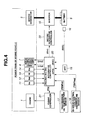
- any of the first, second and third power trains shown in FIGS. 1-3 may be controlled by a control system as shown in FIG. 4 .
- the control system is applicable to all of these power trains, as well as other power trains not shown, the following explanation is made with particular regard to the third power train shown in FIG. 3 wherein one of the friction elements of automatic transmission 3 is used as second clutch 7.
- the control system of FIG. 4 has an integrated controller 20 to control the operation points of the power train.
- the power train operation points are herein defined by a target torque tTe of engine 1, a target torque tTm of motor/generator 5, a target transmission torque capacity tTc1 of first clutch 6 and a target transmission torque capacity tTc2 of second clutch 7.
- Integrated controller 20 is, for example, a microcomputer including a random access memory (RAM), a read-only memory (ROM) and a central processing unit (CPU) in addition to various input and output connections.
- RAM random access memory
- ROM read-only memory
- CPU central processing unit
- the control functions described herein are performed by execution by the CPU of one or more software programs stored in ROM.
- some or all of the functions of integrated controller 20 can be implemented by hardware components.
- integrated controller 20 receives a signal from an engine rotation sensor 11 for detecting a rotational speed Ne of engine 1, a signal from motor/generator rotation sensor 12 for detecting a rotational speed Nm of motor/generator 5, a signal from a transmission input rotation sensor 13 for detecting a rotational speed Ni of transmission input shaft 3a, a signal from a transmission output rotation sensor 14 for detecting a rotational speed No of transmission output shaft 3b, a signal from an accelerator opening sensor 15 for detecting an accelerator pedal depression amount (accelerator opening APO) corresponding to a requested load of engine 1, a signal from a storage state sensor 16 for detecting a stage of charge SOC of a battery 9 (or an amount of electrical power that can be taken out of battery 9), a signal from a transmission oil temperature sensor 17 for detecting an operating oil temperature TEMPat of automatic transmission 3 corresponding to a temperature of second clutch 7 and a signal from an electric drive control coolant temperature sensor 18 for detecting a coolant temperature
- integrated controller 20 Based on the accelerator opening APO, the battery charge state SOC and the transmission output rotational speed No (vehicle speed VSP), integrated controller 20 carries out vehicle drive control operation by selecting either the EV mode or the HEV mode to achieve a vehicle driving force according to a driver's request and calculating the target engine torque tTe, the target motor/generator torque tTm, the target first clutch transmission torque capacity tTc1 and the target second clutch transmission torque capacity tTc2.
- the target engine torque tTe is output by integrated controller 20 to engine controller 21 so that engine controller 21 controls engine 1 to adjust the actual engine torque Te to the target engine torque tTe.
- the target motor/generator torque tTm is output from integrated controller 20 to motor/generator controller 22 so that motor/generator controller 22 controls motor/generator 5 using battery 9 and inverter 10 to adjust the actual motor/generator torque Tm to the target motor/generator torque tTm.
- Integrated controller 20 further supplies solenoid control currents to first and second clutches 6 and 7 in order to adjust the actual torque transmission capacities Tc1 and Tc2 to the target torque transmission capacities tTc1 and tTc2, respectively, for individual clutch engagement control.
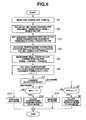
- Integrated controller 20 is configured to control mode changeover (mode selection) between the EV mode and the HEV mode by executing a control program such as that shown in the flowchart of FIG. 5 .
- step S1 integrated controller 20 reads vehicle speed VSP, transmission oil temperature TEMPat and electric drive control coolant temperature TEMPmg.
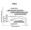
- step S2 integrated controller 20 sets an EV-to-HEV mode changeover judgment accelerator opening threshold level ⁇ based on an EV-to-HEV mode changeover judgment accelerator opening threshold line as indicated by a solid line in FIG. 6 .
- the EV-to-HEV mode changeover judgment threshold line (level ⁇ ) is used to judge whether to allow a changeover from the EV mode to the HEV mode when the accelerator opening APO becomes greater than or equal to the judgment threshold level ⁇ at a respective vehicle speed VSP.
- the EV-to-HEV mode changeover judgment threshold level ⁇ is set constant irrespective of the vehicle speed VSP within a given vehicle speed range.
- the EV-to-HEV mode changeover judgment threshold level ⁇ corresponds to an upper limit of the accelerator opening APO, with respect to each vehicle speed VSP, at which motor/generator 5 can be operated for EV driving so as to preserve a sufficient motor torque for engine start at the time of changeover from the EV mode to the HEV mode, and can be predetermined, for example, by experimentation. If the accelerator opening APO is greater than the EV-to-HEV mode changeover judgment threshold line (level ⁇ ) during the EV mode, motor/generator 5 uses a large torque to rotate driving wheels 2 and cannot produce a sufficient torque to start engine 1 at the changeover from the EV mode to the HEV mode. This results in a failure of the changeover from the EV mode to the HEV mode.
- step S3 integrated controller 20 sets an ordinary-temperature HEV-to-EV mode changeover judgment accelerator opening threshold level ⁇ based on an ordinary-temperature HEV-to-EV mode changeover judgment accelerator opening threshold line as indicated by a broken line in FIG. 6 .
- the ordinary-temperature HEV-to-EV mode changeover judgment threshold line (level ⁇ ) is used to judge whether to allow a changeover from the HEV mode to the EV mode with engine stop when the accelerator opening APO becomes smaller than the judgment threshold level ⁇ with respect to each vehicle speed VSP under ordinary temperature conditions after warm-up.
- the ordinary-temperature HEV-to-EV mode changeover judgment threshold level ⁇ is set lower than the HEV-to-EV mode changeover judgment threshold level ⁇ , so that there is hysteresis ⁇ APO between these judgment threshold levels ⁇ and ⁇ .
- the ordinary-temperature HEV-to-EV mode changeover judgment threshold line (level ⁇ ) is lowered with respect to the HEV-to-EV mode changeover judgment threshold line (level ⁇ ) in such a manner that the amount (width) of hysteresis ⁇ APO increases as the vehicle speed decreases, as explained hereinafter.
- the ordinary-temperature HEV-to-EV mode changeover judgment threshold level ⁇ decreases at a constant gradient with respect to the vehicle speed in FIG. 6 , but may alternatively decrease in a non-constant manner, for example, in steps.
- integrated controller 20 retrieves an oil temperature correction factor Ktempat (0 ⁇ Ktempat ⁇ 1), relative to the ordinary-temperature HEV-to-EV mode changeover judgment threshold line (level ⁇ ), based on the vehicle speed VSP and the transmission oil temperature TEMPat (i.e., the temperature of second clutch 7). Also at step S4, integrated controller 20 retrieves a coolant temperature correction factor Ktempmg (0 ⁇ Ktempmg ⁇ 1), relative to the ordinary-temperature HEV-to-EV mode changeover judgment threshold line (level ⁇ ), based on the vehicle speed VSP and electric drive control coolant temperature TEMPmg (i.e., the temperature of electric drive control system including motor/generator 5 and inverter 10). Both of the oil temperature correction factor Ktempat and the coolant temperature correction factor Ktempmg decrease with increase in temperature and decrease with vehicle speed.
- both the oil temperature correction factor Ktempat (0 ⁇ Ktempat ⁇ 1) and the coolant temperature correction factor Ktempmg (0 ⁇ Ktempmg ⁇ 1) decrease with increases in temperature and decrease with vehicle speed.
- the final temperature correction factor Ktemp (0 ⁇ Ktemp ⁇ 1) which is obtained by multiplying Ktempat by Ktempmg, also decreases with increases in temperature and decreases with vehicle speed.
- the amount of hysteresis ⁇ APO between the EV-to-HEV mode changeover judgment threshold line (level ⁇ ) and the high-temperature HEV-to-EV mode changeover judgment threshold line (level ⁇ ) is made larger than that between the EV-to-HEV mode changeover judgment threshold line (level ⁇ ) and the ordinary-temperature HEV-to-EV mode changeover judgment threshold line (level ⁇ ).
- This hysteresis ⁇ APO increases with the transmission oil temperature TEMPat (the temperature of second clutch 7) and the electric drive control coolant temperature TEMPmg (the temperature of the electric drive control system including motor/generator 5 and inverter 10) and increases with decrease in the vehicle speed VSP.
- the high-temperature HEV-to-EV mode changeover judgment threshold line (level ⁇ ) coincides with the ordinary-temperature HEV-to-EV mode changeover judgment threshold line (level ⁇ ) when the correction factor Ktemp is set to 1 at ordinary temperature.
- step S7 integrated controller 20 judges whether the current selection mode is in either the EV mode or the HEV mode.
- step S7 If it is judged at step S7 that the EV mode is selected, integrated controller 20 checks at step S8 whether the accelerator opening APO is greater than or equal to the EV-to-HEV mode changeover judgment threshold level ⁇ .
- integrated controller 20 allows a changeover from the EV mode to the HEV mode at step S9. If APO ⁇ ⁇ , integrated controller 20 maintains the currently selected EV mode at step S10.
- integrated controller 20 checks at step S11 whether the accelerator opening APO is smaller than the high-temperature HEV-to-EV mode changeover judgment threshold level ⁇ (which coincides with the ordinary-temperature HEV-to-EV mode changeover judgment threshold level ⁇ at ordinary temperature).
- integrated controller 20 allows a changeover from the HEV mode to the EV mode at step S12. If APO ⁇ ⁇ , integrated controller 20 maintains the currently selected HEV mode at step S13.
- VSP vehicle speed
- TEMPat and TEMPmg driving environment
- This prevents frequent changeovers from the EV mode to the HEV mode accompanied by starting of the engine and from the HEV mode to the EV mode accompanied by stopping of the engine in response to large accelerator opening changes.
- it is possible to reduce deteriorations in vehicle fuel efficiency and driving performance that would be caused by frequent mode changeovers.
- VSP high vehicle speed
- SOC dischargeable battery power
- the accelerator opening hysteresis ⁇ APO is changed depending on not only the vehicle speed conditions (vehicle operating state) but also the vehicle driving environment (temperatures TEMPat and TEMPmg) so that the hysteresis ⁇ APO increases as the transmission oil temperature TEMPat (the temperature of second clutch 7) becomes higher than the ordinary temperature and increases as the electric drive control coolant temperature TEMPmg (the temperature of electric drive control system including motor/generator 5 and inverter 10) becomes higher than the ordinary temperature.
- ⁇ APO ⁇ - ⁇
- VSP vehicle speed
- TEMPat and TEMPmg driving environment
- the EV-to-HEV mode changeover judgment threshold level ⁇ generally corresponds to the upper limit of the accelerator opening APO at which motor/generator 5 can be operated for EV driving so as to preserve a sufficient motor torque for engine start at the time of changeover from the EV mode to the HEV mode. If the accelerator opening APO is greater than the EV-to-HEV mode changeover judgment threshold level ⁇ under the EV mode, motor/generator 5 uses a large torque to rotate driving wheels 2 and cannot produce a sufficient torque to start engine 1 at the changeover from the EV mode to the HEV mode. This results in a failure of the changeover from the EV mode to the HEV mode.
Landscapes
- Engineering & Computer Science (AREA)
- Mechanical Engineering (AREA)
- Transportation (AREA)
- Combustion & Propulsion (AREA)
- Chemical & Material Sciences (AREA)
- Automation & Control Theory (AREA)
- Power Engineering (AREA)
- Life Sciences & Earth Sciences (AREA)
- Sustainable Development (AREA)
- Sustainable Energy (AREA)
- Physics & Mathematics (AREA)
- Mathematical Physics (AREA)
- Electric Propulsion And Braking For Vehicles (AREA)
- Hybrid Electric Vehicles (AREA)
Applications Claiming Priority (2)
| Application Number | Priority Date | Filing Date | Title |
|---|---|---|---|
| JP2006349851 | 2006-12-26 | ||
| JP2007240878A JP5088058B2 (ja) | 2006-12-26 | 2007-09-18 | ハイブリッド車両のモード切り替え制御装置 |
Publications (3)
| Publication Number | Publication Date |
|---|---|
| EP1939059A2 true EP1939059A2 (de) | 2008-07-02 |
| EP1939059A3 EP1939059A3 (de) | 2008-09-03 |
| EP1939059B1 EP1939059B1 (de) | 2010-07-14 |
Family
ID=39148751
Family Applications (1)
| Application Number | Title | Priority Date | Filing Date |
|---|---|---|---|
| EP07150202A Ceased EP1939059B1 (de) | 2006-12-26 | 2007-12-20 | System zur Moduswechselsteuerung für ein Hybridfahrzeug |
Country Status (2)
| Country | Link |
|---|---|
| US (1) | US8060266B2 (de) |
| EP (1) | EP1939059B1 (de) |
Cited By (9)
| Publication number | Priority date | Publication date | Assignee | Title |
|---|---|---|---|---|
| EP2236374A1 (de) * | 2009-03-30 | 2010-10-06 | JATCO Ltd | Appareil de commande pour véhicule hybride |
| WO2012130845A3 (de) * | 2011-03-29 | 2012-11-22 | Getrag Getriebe- Und Zahnradfabrik Hermann Hagenmeyer Gmbh & Cie Kg | Verfahren zum betreiben eines hybrid-antriebsstranges |
| WO2015036823A1 (en) * | 2013-09-12 | 2015-03-19 | Toyota Jidosha Kabushiki Kaisha | Control apparatus for hybrid vehicle |
| US9162664B2 (en) | 2010-05-05 | 2015-10-20 | Ford Global Technologies, Inc. | Vehicle and method for controlling an electric machine and/or engine therein |
| EP2792562A4 (de) * | 2011-12-15 | 2016-01-27 | Toyota Motor Co Ltd | Hybridfahrzeug |
| EP2985171A1 (de) * | 2014-08-12 | 2016-02-17 | Hyundai Motor Company | Erzwungenes Ladeverfahren für PHEV-Fahrzeuge mit Motor und HSG |
| EP2631133A4 (de) * | 2010-10-21 | 2016-12-28 | Nissan Motor | Vorrichtung zur steuerung der schnellen entschleunigung eines hybridfahrzeugs |
| GB2553172A (en) * | 2017-04-13 | 2018-02-28 | Detroit Electric Ev Ltd | Electrical vehicle drive train and method of operation |
| US10024249B2 (en) | 2012-01-30 | 2018-07-17 | Jaguar Land Rover Limited | Motor vehicle controller and method of controlling a motor vehicle |
Families Citing this family (16)
| Publication number | Priority date | Publication date | Assignee | Title |
|---|---|---|---|---|
| US7846051B2 (en) * | 2007-05-11 | 2010-12-07 | Gm Global Technology Operations, Inc. | Hybrid powertrain with an engine input clutch and method of control |
| JP5680279B2 (ja) * | 2008-03-06 | 2015-03-04 | 日産自動車株式会社 | ハイブリッド車両のエンジン停止制御装置 |
| US8346421B2 (en) * | 2009-03-24 | 2013-01-01 | Ford Global Technologies, Llc | Method and system for initiating starting of an engine in a hybrid electric vehicle |
| US8087483B2 (en) * | 2009-05-26 | 2012-01-03 | GM Global Technology Operations LLC | Hybrid powertrain with torque-multiplying engine starting mechanism and method of controlling a hybrid powertrain |
| CN102114766B (zh) * | 2009-12-31 | 2014-03-19 | 比亚迪股份有限公司 | 一种混合动力驱动系统及其驱动方法 |
| JP5742124B2 (ja) * | 2010-07-21 | 2015-07-01 | 日産自動車株式会社 | ハイブリッド車両の制御装置 |
| US9180869B2 (en) * | 2011-11-11 | 2015-11-10 | Toyota Jidosha Kabushiki Kaisha | Hybrid drive system |
| JP5962463B2 (ja) * | 2012-11-27 | 2016-08-03 | 三菱自動車工業株式会社 | エンジン始動判定装置 |
| KR101405198B1 (ko) * | 2012-12-07 | 2014-06-27 | 기아자동차 주식회사 | 하이브리드 차량의 안티 저크 제어 방법 및 시스템 |
| US9031722B2 (en) * | 2012-12-10 | 2015-05-12 | Ford Global Technologies, Llc | Method and system for improving hybrid vehicle shifting |
| JP5967110B2 (ja) * | 2013-01-08 | 2016-08-10 | トヨタ自動車株式会社 | ハイブリッド車両の制御装置 |
| EP3173281B1 (de) * | 2014-07-23 | 2021-04-07 | Nissan Motor Co., Ltd | Motorsteuerungsvorrichtung und motorsteuerungsverfahren |
| US10112597B2 (en) | 2016-08-23 | 2018-10-30 | Ford Global Technologies, Llc | Automatic drive mode selection |
| KR101813542B1 (ko) * | 2016-10-06 | 2018-01-30 | 현대자동차주식회사 | 하이브리드 차량 및 그 제어 방법 |
| CN111746259A (zh) * | 2019-03-29 | 2020-10-09 | 乾碳国际公司 | 重卡节油机器人装置和控制方法 |
| JP7023906B2 (ja) * | 2019-09-06 | 2022-02-22 | 本田技研工業株式会社 | 車両の制御装置 |
Citations (4)
| Publication number | Priority date | Publication date | Assignee | Title |
|---|---|---|---|---|
| JPH0648190A (ja) | 1992-07-27 | 1994-02-22 | Aqueous Res:Kk | ハイブリッド型車両 |
| US5846155A (en) | 1995-07-19 | 1998-12-08 | Aisin Aw Co., Ltd. | Vehicular drive unit |
| US6428444B1 (en) | 1999-09-06 | 2002-08-06 | Toyota Jidosha Kabushiki Kaisha | Apparatus for controlling a vehicle and a method of controlling the vehicle |
| EP1375237A2 (de) | 1997-09-15 | 2004-01-02 | Honda Giken Kogyo Kabushiki Kaisha | Vorrichtung zur Steuerung eines Hybridfahrzeuges |
Family Cites Families (17)
| Publication number | Priority date | Publication date | Assignee | Title |
|---|---|---|---|---|
| DE2943554A1 (de) * | 1979-10-27 | 1981-05-07 | Volkswagenwerk Ag | Hybrid-antrieb fuer ein fahrzeug, insbesondere kraftfahrzeug |
| US4405029A (en) * | 1980-01-02 | 1983-09-20 | Hunt Hugh S | Hybrid vehicles |
| US4470476A (en) * | 1981-11-16 | 1984-09-11 | Hunt Hugh S | Hybrid vehicles |
| KR0139981B1 (ko) * | 1995-06-12 | 1998-07-15 | 김광호 | 일정한 문턱전압을 갖는 히스테리시스 시스템 |
| JP3870505B2 (ja) | 1997-08-29 | 2007-01-17 | アイシン・エィ・ダブリュ株式会社 | 車両用ハイブリッド駆動装置 |
| EP0901930B1 (de) * | 1997-09-15 | 2004-07-14 | Honda Giken Kogyo Kabushiki Kaisha | Vorrichtung zur Steuerung eines Hybridfahrzeuges |
| JP3172490B2 (ja) | 1998-05-18 | 2001-06-04 | 株式会社日立製作所 | ハイブリッド車 |
| JP3369484B2 (ja) * | 1998-09-02 | 2003-01-20 | 本田技研工業株式会社 | ハイブリッド駆動車両の制御装置 |
| US6554088B2 (en) * | 1998-09-14 | 2003-04-29 | Paice Corporation | Hybrid vehicles |
| DE10204982A1 (de) | 2002-02-06 | 2003-08-14 | Daimler Chrysler Ag | Hybridantrieb für Kraftfahrzeuge |
| JP3906717B2 (ja) * | 2002-03-19 | 2007-04-18 | トヨタ自動車株式会社 | アクセル開度設定装置およびこれを備える自動車 |
| DE10260435A1 (de) * | 2002-12-21 | 2004-07-01 | Volkswagen Ag | Verfahren zur Steuerung eines KFZ-Hybridantriebes |
| DE102004006730A1 (de) | 2003-02-12 | 2004-08-26 | Luk Lamellen Und Kupplungsbau Beteiligungs Kg | Verfahren zum Durchführen von zumindest einer Schutzstrategie für die Kupplung eines automatisierten Schaltgetriebes eines Fahrzeuges |
| JP2004364453A (ja) | 2003-06-06 | 2004-12-24 | Aisin Aw Co Ltd | 電動車両駆動制御装置、電動車両駆動制御方法及びそのプログラム |
| JP3701660B2 (ja) * | 2003-07-04 | 2005-10-05 | 本田技研工業株式会社 | ハイブリッド車両の制御装置 |
| DE102004002061A1 (de) | 2004-01-15 | 2005-08-04 | Zf Friedrichshafen Ag | Verfahren zum Steuern und Regeln eines Antriebsstranges eines Hybridfahrzeuges und Antriebsstrang eines Hybridfahrzeugs |
| DE102004040315A1 (de) | 2004-08-20 | 2006-03-02 | Volkswagen Ag | Verfahren zum Betreiben eines Hybrid Kraftfahrzeuges |
-
2007
- 2007-12-18 US US11/958,622 patent/US8060266B2/en active Active
- 2007-12-20 EP EP07150202A patent/EP1939059B1/de not_active Ceased
Patent Citations (4)
| Publication number | Priority date | Publication date | Assignee | Title |
|---|---|---|---|---|
| JPH0648190A (ja) | 1992-07-27 | 1994-02-22 | Aqueous Res:Kk | ハイブリッド型車両 |
| US5846155A (en) | 1995-07-19 | 1998-12-08 | Aisin Aw Co., Ltd. | Vehicular drive unit |
| EP1375237A2 (de) | 1997-09-15 | 2004-01-02 | Honda Giken Kogyo Kabushiki Kaisha | Vorrichtung zur Steuerung eines Hybridfahrzeuges |
| US6428444B1 (en) | 1999-09-06 | 2002-08-06 | Toyota Jidosha Kabushiki Kaisha | Apparatus for controlling a vehicle and a method of controlling the vehicle |
Cited By (14)
| Publication number | Priority date | Publication date | Assignee | Title |
|---|---|---|---|---|
| EP2236374A1 (de) * | 2009-03-30 | 2010-10-06 | JATCO Ltd | Appareil de commande pour véhicule hybride |
| US8512201B2 (en) | 2009-03-30 | 2013-08-20 | Jatco Ltd | Control apparatus for hybrid vehicle |
| US9162664B2 (en) | 2010-05-05 | 2015-10-20 | Ford Global Technologies, Inc. | Vehicle and method for controlling an electric machine and/or engine therein |
| EP2631133A4 (de) * | 2010-10-21 | 2016-12-28 | Nissan Motor | Vorrichtung zur steuerung der schnellen entschleunigung eines hybridfahrzeugs |
| WO2012130845A3 (de) * | 2011-03-29 | 2012-11-22 | Getrag Getriebe- Und Zahnradfabrik Hermann Hagenmeyer Gmbh & Cie Kg | Verfahren zum betreiben eines hybrid-antriebsstranges |
| US8831812B2 (en) | 2011-03-29 | 2014-09-09 | Getrag Getriebe- Und Zahnradfabrik Hermann Hagenmeyer Gmbh & Cie Kg | Method for operating a hybrid drivetrain |
| EP2792562A4 (de) * | 2011-12-15 | 2016-01-27 | Toyota Motor Co Ltd | Hybridfahrzeug |
| US10024249B2 (en) | 2012-01-30 | 2018-07-17 | Jaguar Land Rover Limited | Motor vehicle controller and method of controlling a motor vehicle |
| WO2015036823A1 (en) * | 2013-09-12 | 2015-03-19 | Toyota Jidosha Kabushiki Kaisha | Control apparatus for hybrid vehicle |
| EP2985171A1 (de) * | 2014-08-12 | 2016-02-17 | Hyundai Motor Company | Erzwungenes Ladeverfahren für PHEV-Fahrzeuge mit Motor und HSG |
| CN105365809A (zh) * | 2014-08-12 | 2016-03-02 | 现代自动车株式会社 | 使用电动机和hsg对phev车辆的强制充电方法 |
| US9428174B2 (en) | 2014-08-12 | 2016-08-30 | Hyundai Motor Company | Forced charging method for PHEV vehicles using motor and HSG |
| CN105365809B (zh) * | 2014-08-12 | 2019-05-28 | 现代自动车株式会社 | 使用电动机和hsg对phev车辆的强制充电方法 |
| GB2553172A (en) * | 2017-04-13 | 2018-02-28 | Detroit Electric Ev Ltd | Electrical vehicle drive train and method of operation |
Also Published As
| Publication number | Publication date |
|---|---|
| EP1939059A3 (de) | 2008-09-03 |
| US20080154455A1 (en) | 2008-06-26 |
| EP1939059B1 (de) | 2010-07-14 |
| US8060266B2 (en) | 2011-11-15 |
Similar Documents
| Publication | Publication Date | Title |
|---|---|---|
| EP1939059B1 (de) | System zur Moduswechselsteuerung für ein Hybridfahrzeug | |
| CN101209711B (zh) | 用于混合动力车辆的模式转换控制装置 | |
| US7686112B2 (en) | Apparatus and method for controlling hybrid vehicle | |
| US8132635B2 (en) | Motor lock prevention control for hybrid electric vehicle | |
| US9186975B2 (en) | Control apparatus for hybrid vehicle | |
| EP1862364B1 (de) | Fahrzeugsteuerung | |
| EP2631133B1 (de) | Vorrichtung zur steuerung der schnellen entschleunigung eines hybridfahrzeugs | |
| US8204659B2 (en) | Engine start control system for hybrid vehicle | |
| JP5832736B2 (ja) | ハイブリッド車両のエンジン始動制御装置 | |
| KR101423007B1 (ko) | 하이브리드 차량을 제어하기 위한 장치 및 방법 | |
| US8738209B2 (en) | Control device of vehicle drive apparatus | |
| US9216734B2 (en) | Control device | |
| JP5262197B2 (ja) | ハイブリッド車両の制御装置 | |
| JP5125727B2 (ja) | ハイブリッド車両の発進制御装置 | |
| US8983703B2 (en) | Device for controlling hybrid vehicle | |
| EP2826655A2 (de) | Steuerungsvorrichtung eines Hybrid-Elektrofahrzeug | |
| JP2012116272A (ja) | ハイブリッド電気自動車の回生制御装置 | |
| JP5217396B2 (ja) | ハイブリッド車両の制御装置 | |
| US9321456B2 (en) | Hybrid vehicle control device | |
| JP5287825B2 (ja) | ハイブリッド車両のアイドル制御装置 |
Legal Events
| Date | Code | Title | Description |
|---|---|---|---|
| PUAI | Public reference made under article 153(3) epc to a published international application that has entered the european phase |
Free format text: ORIGINAL CODE: 0009012 |
|
| AK | Designated contracting states |
Kind code of ref document: A2 Designated state(s): AT BE BG CH CY CZ DE DK EE ES FI FR GB GR HU IE IS IT LI LT LU LV MC MT NL PL PT RO SE SI SK TR |
|
| AX | Request for extension of the european patent |
Extension state: AL BA HR MK RS |
|
| PUAL | Search report despatched |
Free format text: ORIGINAL CODE: 0009013 |
|
| AK | Designated contracting states |
Kind code of ref document: A3 Designated state(s): AT BE BG CH CY CZ DE DK EE ES FI FR GB GR HU IE IS IT LI LT LU LV MC MT NL PL PT RO SE SI SK TR |
|
| AX | Request for extension of the european patent |
Extension state: AL BA HR MK RS |
|
| 17P | Request for examination filed |
Effective date: 20090303 |
|
| 17Q | First examination report despatched |
Effective date: 20090407 |
|
| AKX | Designation fees paid |
Designated state(s): DE FR GB |
|
| GRAP | Despatch of communication of intention to grant a patent |
Free format text: ORIGINAL CODE: EPIDOSNIGR1 |
|
| GRAS | Grant fee paid |
Free format text: ORIGINAL CODE: EPIDOSNIGR3 |
|
| GRAA | (expected) grant |
Free format text: ORIGINAL CODE: 0009210 |
|
| AK | Designated contracting states |
Kind code of ref document: B1 Designated state(s): DE FR GB |
|
| REG | Reference to a national code |
Ref country code: GB Ref legal event code: FG4D |
|
| REF | Corresponds to: |
Ref document number: 602007007719 Country of ref document: DE Date of ref document: 20100826 Kind code of ref document: P |
|
| PLBE | No opposition filed within time limit |
Free format text: ORIGINAL CODE: 0009261 |
|
| STAA | Information on the status of an ep patent application or granted ep patent |
Free format text: STATUS: NO OPPOSITION FILED WITHIN TIME LIMIT |
|
| 26N | No opposition filed |
Effective date: 20110415 |
|
| REG | Reference to a national code |
Ref country code: DE Ref legal event code: R097 Ref document number: 602007007719 Country of ref document: DE Effective date: 20110415 |
|
| REG | Reference to a national code |
Ref country code: FR Ref legal event code: PLFP Year of fee payment: 9 |
|
| REG | Reference to a national code |
Ref country code: FR Ref legal event code: PLFP Year of fee payment: 10 |
|
| REG | Reference to a national code |
Ref country code: FR Ref legal event code: PLFP Year of fee payment: 11 |
|
| PGFP | Annual fee paid to national office [announced via postgrant information from national office to epo] |
Ref country code: GB Payment date: 20231124 Year of fee payment: 17 |
|
| PGFP | Annual fee paid to national office [announced via postgrant information from national office to epo] |
Ref country code: FR Payment date: 20231122 Year of fee payment: 17 Ref country code: DE Payment date: 20231121 Year of fee payment: 17 |
|
| REG | Reference to a national code |
Ref country code: DE Ref legal event code: R119 Ref document number: 602007007719 Country of ref document: DE |
|
| GBPC | Gb: european patent ceased through non-payment of renewal fee |
Effective date: 20241220 |
|
| PG25 | Lapsed in a contracting state [announced via postgrant information from national office to epo] |
Ref country code: DE Free format text: LAPSE BECAUSE OF NON-PAYMENT OF DUE FEES Effective date: 20250701 |
|
| PG25 | Lapsed in a contracting state [announced via postgrant information from national office to epo] |
Ref country code: GB Free format text: LAPSE BECAUSE OF NON-PAYMENT OF DUE FEES Effective date: 20241220 |
|
| PG25 | Lapsed in a contracting state [announced via postgrant information from national office to epo] |
Ref country code: FR Free format text: LAPSE BECAUSE OF NON-PAYMENT OF DUE FEES Effective date: 20241231 |