EP1939325A2 - Revêtement de protection de corrosion tolérant en contrainte et procédé d'application par bande - Google Patents
Revêtement de protection de corrosion tolérant en contrainte et procédé d'application par bande Download PDFInfo
- Publication number
- EP1939325A2 EP1939325A2 EP07122504A EP07122504A EP1939325A2 EP 1939325 A2 EP1939325 A2 EP 1939325A2 EP 07122504 A EP07122504 A EP 07122504A EP 07122504 A EP07122504 A EP 07122504A EP 1939325 A2 EP1939325 A2 EP 1939325A2
- Authority
- EP
- European Patent Office
- Prior art keywords
- coating
- corrosion resistant
- particles
- weight percent
- corrosion
- Prior art date
- Legal status (The legal status is an assumption and is not a legal conclusion. Google has not performed a legal analysis and makes no representation as to the accuracy of the status listed.)
- Withdrawn
Links
- 238000000576 coating method Methods 0.000 title claims abstract description 133
- 239000011248 coating agent Substances 0.000 title claims abstract description 118
- 238000005260 corrosion Methods 0.000 title claims abstract description 97
- 230000007797 corrosion Effects 0.000 title claims abstract description 96
- 238000000034 method Methods 0.000 title description 22
- PNEYBMLMFCGWSK-UHFFFAOYSA-N aluminium oxide Inorganic materials [O-2].[O-2].[O-2].[Al+3].[Al+3] PNEYBMLMFCGWSK-UHFFFAOYSA-N 0.000 claims abstract description 45
- 239000000758 substrate Substances 0.000 claims abstract description 33
- 239000011159 matrix material Substances 0.000 claims abstract description 20
- 239000000919 ceramic Substances 0.000 claims abstract description 14
- 239000008199 coating composition Substances 0.000 claims description 39
- 239000000203 mixture Substances 0.000 claims description 37
- 239000011230 binding agent Substances 0.000 claims description 31
- 229920001296 polysiloxane Polymers 0.000 claims description 22
- 239000002904 solvent Substances 0.000 claims description 21
- 239000004014 plasticizer Substances 0.000 claims description 18
- PXHVJJICTQNCMI-UHFFFAOYSA-N Nickel Chemical compound [Ni] PXHVJJICTQNCMI-UHFFFAOYSA-N 0.000 claims description 17
- XEEYBQQBJWHFJM-UHFFFAOYSA-N Iron Chemical compound [Fe] XEEYBQQBJWHFJM-UHFFFAOYSA-N 0.000 claims description 15
- 229910000601 superalloy Inorganic materials 0.000 claims description 12
- GWEVSGVZZGPLCZ-UHFFFAOYSA-N Titan oxide Chemical compound O=[Ti]=O GWEVSGVZZGPLCZ-UHFFFAOYSA-N 0.000 claims description 10
- CPLXHLVBOLITMK-UHFFFAOYSA-N Magnesium oxide Chemical compound [Mg]=O CPLXHLVBOLITMK-UHFFFAOYSA-N 0.000 claims description 9
- 229910052782 aluminium Inorganic materials 0.000 claims description 9
- XAGFODPZIPBFFR-UHFFFAOYSA-N aluminium Chemical compound [Al] XAGFODPZIPBFFR-UHFFFAOYSA-N 0.000 claims description 9
- 229910052759 nickel Inorganic materials 0.000 claims description 9
- RUDFQVOCFDJEEF-UHFFFAOYSA-N yttrium(III) oxide Inorganic materials [O-2].[O-2].[O-2].[Y+3].[Y+3] RUDFQVOCFDJEEF-UHFFFAOYSA-N 0.000 claims description 9
- 241000588731 Hafnia Species 0.000 claims description 8
- UQSXHKLRYXJYBZ-UHFFFAOYSA-N Iron oxide Chemical compound [Fe]=O UQSXHKLRYXJYBZ-UHFFFAOYSA-N 0.000 claims description 8
- CJNBYAVZURUTKZ-UHFFFAOYSA-N hafnium(IV) oxide Inorganic materials O=[Hf]=O CJNBYAVZURUTKZ-UHFFFAOYSA-N 0.000 claims description 8
- 229910052742 iron Inorganic materials 0.000 claims description 8
- VYZAMTAEIAYCRO-UHFFFAOYSA-N Chromium Chemical compound [Cr] VYZAMTAEIAYCRO-UHFFFAOYSA-N 0.000 claims description 7
- 229910052804 chromium Inorganic materials 0.000 claims description 7
- 239000011651 chromium Substances 0.000 claims description 7
- 238000010438 heat treatment Methods 0.000 claims description 7
- 229910019901 yttrium aluminum garnet Inorganic materials 0.000 claims description 7
- JNDMLEXHDPKVFC-UHFFFAOYSA-N aluminum;oxygen(2-);yttrium(3+) Chemical compound [O-2].[O-2].[O-2].[Al+3].[Y+3] JNDMLEXHDPKVFC-UHFFFAOYSA-N 0.000 claims description 6
- 229910017052 cobalt Inorganic materials 0.000 claims description 6
- 239000010941 cobalt Substances 0.000 claims description 6
- GUTLYIVDDKVIGB-UHFFFAOYSA-N cobalt atom Chemical compound [Co] GUTLYIVDDKVIGB-UHFFFAOYSA-N 0.000 claims description 6
- QDOXWKRWXJOMAK-UHFFFAOYSA-N dichromium trioxide Chemical compound O=[Cr]O[Cr]=O QDOXWKRWXJOMAK-UHFFFAOYSA-N 0.000 claims description 6
- 239000011521 glass Substances 0.000 claims description 6
- CETPSERCERDGAM-UHFFFAOYSA-N ceric oxide Chemical compound O=[Ce]=O CETPSERCERDGAM-UHFFFAOYSA-N 0.000 claims description 5
- 229910000422 cerium(IV) oxide Inorganic materials 0.000 claims description 5
- 229910052727 yttrium Inorganic materials 0.000 claims description 5
- MCMNRKCIXSYSNV-UHFFFAOYSA-N Zirconium dioxide Chemical compound O=[Zr]=O MCMNRKCIXSYSNV-UHFFFAOYSA-N 0.000 claims description 4
- JOPOVCBBYLSVDA-UHFFFAOYSA-N chromium(6+) Chemical compound [Cr+6] JOPOVCBBYLSVDA-UHFFFAOYSA-N 0.000 claims description 4
- 239000000395 magnesium oxide Substances 0.000 claims description 4
- VWQVUPCCIRVNHF-UHFFFAOYSA-N yttrium atom Chemical compound [Y] VWQVUPCCIRVNHF-UHFFFAOYSA-N 0.000 claims description 3
- 229910052796 boron Inorganic materials 0.000 claims description 2
- KPUWHANPEXNPJT-UHFFFAOYSA-N disiloxane Chemical class [SiH3]O[SiH3] KPUWHANPEXNPJT-UHFFFAOYSA-N 0.000 claims description 2
- 229910052735 hafnium Inorganic materials 0.000 claims description 2
- 229910052702 rhenium Inorganic materials 0.000 claims description 2
- 229910052715 tantalum Inorganic materials 0.000 claims description 2
- 229910052726 zirconium Inorganic materials 0.000 claims description 2
- 239000003125 aqueous solvent Substances 0.000 claims 1
- 229910001233 yttria-stabilized zirconia Inorganic materials 0.000 claims 1
- 239000002245 particle Substances 0.000 abstract description 125
- VYPSYNLAJGMNEJ-UHFFFAOYSA-N Silicium dioxide Chemical group O=[Si]=O VYPSYNLAJGMNEJ-UHFFFAOYSA-N 0.000 abstract description 16
- 239000000377 silicon dioxide Substances 0.000 abstract description 6
- 230000001351 cycling effect Effects 0.000 abstract description 2
- 239000010410 layer Substances 0.000 description 40
- 239000007789 gas Substances 0.000 description 21
- 239000000463 material Substances 0.000 description 19
- 238000001035 drying Methods 0.000 description 15
- 239000003570 air Substances 0.000 description 14
- 239000002002 slurry Substances 0.000 description 14
- LFQSCWFLJHTTHZ-UHFFFAOYSA-N Ethanol Chemical compound CCO LFQSCWFLJHTTHZ-UHFFFAOYSA-N 0.000 description 12
- 229910045601 alloy Inorganic materials 0.000 description 12
- 239000000956 alloy Substances 0.000 description 12
- 238000002485 combustion reaction Methods 0.000 description 12
- 229910052751 metal Inorganic materials 0.000 description 12
- 239000002184 metal Substances 0.000 description 12
- 238000001816 cooling Methods 0.000 description 11
- 230000008901 benefit Effects 0.000 description 9
- 238000010304 firing Methods 0.000 description 9
- 238000011068 loading method Methods 0.000 description 9
- 239000000047 product Substances 0.000 description 8
- 239000004094 surface-active agent Substances 0.000 description 8
- -1 zironcia Inorganic materials 0.000 description 8
- 239000000126 substance Substances 0.000 description 7
- OKKJLVBELUTLKV-UHFFFAOYSA-N Methanol Chemical compound OC OKKJLVBELUTLKV-UHFFFAOYSA-N 0.000 description 6
- 229910019142 PO4 Inorganic materials 0.000 description 6
- 239000011247 coating layer Substances 0.000 description 6
- 239000000470 constituent Substances 0.000 description 6
- DOIRQSBPFJWKBE-UHFFFAOYSA-N dibutyl phthalate Chemical compound CCCCOC(=O)C1=CC=CC=C1C(=O)OCCCC DOIRQSBPFJWKBE-UHFFFAOYSA-N 0.000 description 6
- 235000019441 ethanol Nutrition 0.000 description 6
- 239000007788 liquid Substances 0.000 description 6
- 239000010452 phosphate Substances 0.000 description 6
- 238000013461 design Methods 0.000 description 5
- 239000000446 fuel Substances 0.000 description 5
- 229910001026 inconel Inorganic materials 0.000 description 5
- 238000002156 mixing Methods 0.000 description 5
- XLYOFNOQVPJJNP-UHFFFAOYSA-N water Substances O XLYOFNOQVPJJNP-UHFFFAOYSA-N 0.000 description 5
- CSCPPACGZOOCGX-UHFFFAOYSA-N Acetone Chemical compound CC(C)=O CSCPPACGZOOCGX-UHFFFAOYSA-N 0.000 description 4
- 238000005422 blasting Methods 0.000 description 4
- 230000015556 catabolic process Effects 0.000 description 4
- 238000004140 cleaning Methods 0.000 description 4
- 238000006731 degradation reaction Methods 0.000 description 4
- 238000009826 distribution Methods 0.000 description 4
- 230000000694 effects Effects 0.000 description 4
- 239000012530 fluid Substances 0.000 description 4
- NBIIXXVUZAFLBC-UHFFFAOYSA-K phosphate Chemical compound [O-]P([O-])([O-])=O NBIIXXVUZAFLBC-UHFFFAOYSA-K 0.000 description 4
- 239000011819 refractory material Substances 0.000 description 4
- 235000002639 sodium chloride Nutrition 0.000 description 4
- 239000000243 solution Substances 0.000 description 4
- 238000004901 spalling Methods 0.000 description 4
- 230000035882 stress Effects 0.000 description 4
- 229910000951 Aluminide Inorganic materials 0.000 description 3
- KFZMGEQAYNKOFK-UHFFFAOYSA-N Isopropanol Chemical compound CC(C)O KFZMGEQAYNKOFK-UHFFFAOYSA-N 0.000 description 3
- WNLRTRBMVRJNCN-UHFFFAOYSA-L adipate(2-) Chemical compound [O-]C(=O)CCCCC([O-])=O WNLRTRBMVRJNCN-UHFFFAOYSA-L 0.000 description 3
- 238000005229 chemical vapour deposition Methods 0.000 description 3
- 239000000356 contaminant Substances 0.000 description 3
- 238000005336 cracking Methods 0.000 description 3
- 238000000151 deposition Methods 0.000 description 3
- 238000009792 diffusion process Methods 0.000 description 3
- 239000000843 powder Substances 0.000 description 3
- 230000008569 process Effects 0.000 description 3
- 239000011253 protective coating Substances 0.000 description 3
- 238000007788 roughening Methods 0.000 description 3
- 150000003839 salts Chemical class 0.000 description 3
- 229910002076 stabilized zirconia Inorganic materials 0.000 description 3
- 238000010345 tape casting Methods 0.000 description 3
- 238000005382 thermal cycling Methods 0.000 description 3
- NXQMCAOPTPLPRL-UHFFFAOYSA-N 2-(2-benzoyloxyethoxy)ethyl benzoate Chemical compound C=1C=CC=CC=1C(=O)OCCOCCOC(=O)C1=CC=CC=C1 NXQMCAOPTPLPRL-UHFFFAOYSA-N 0.000 description 2
- MQIUGAXCHLFZKX-UHFFFAOYSA-N Di-n-octyl phthalate Natural products CCCCCCCCOC(=O)C1=CC=CC=C1C(=O)OCCCCCCCC MQIUGAXCHLFZKX-UHFFFAOYSA-N 0.000 description 2
- LYCAIKOWRPUZTN-UHFFFAOYSA-N Ethylene glycol Chemical compound OCCO LYCAIKOWRPUZTN-UHFFFAOYSA-N 0.000 description 2
- 229910015372 FeAl Inorganic materials 0.000 description 2
- KRHYYFGTRYWZRS-UHFFFAOYSA-N Fluorane Chemical compound F KRHYYFGTRYWZRS-UHFFFAOYSA-N 0.000 description 2
- VEXZGXHMUGYJMC-UHFFFAOYSA-N Hydrochloric acid Chemical compound Cl VEXZGXHMUGYJMC-UHFFFAOYSA-N 0.000 description 2
- BPQQTUXANYXVAA-UHFFFAOYSA-N Orthosilicate Chemical compound [O-][Si]([O-])([O-])[O-] BPQQTUXANYXVAA-UHFFFAOYSA-N 0.000 description 2
- XUIMIQQOPSSXEZ-UHFFFAOYSA-N Silicon Chemical compound [Si] XUIMIQQOPSSXEZ-UHFFFAOYSA-N 0.000 description 2
- 125000000217 alkyl group Chemical group 0.000 description 2
- 239000002956 ash Substances 0.000 description 2
- 230000015572 biosynthetic process Effects 0.000 description 2
- BJQHLKABXJIVAM-UHFFFAOYSA-N bis(2-ethylhexyl) phthalate Chemical compound CCCCC(CC)COC(=O)C1=CC=CC=C1C(=O)OCC(CC)CCCC BJQHLKABXJIVAM-UHFFFAOYSA-N 0.000 description 2
- 150000004649 carbonic acid derivatives Chemical class 0.000 description 2
- 238000005266 casting Methods 0.000 description 2
- 150000001805 chlorine compounds Chemical class 0.000 description 2
- ZCDOYSPFYFSLEW-UHFFFAOYSA-N chromate(2-) Chemical compound [O-][Cr]([O-])(=O)=O ZCDOYSPFYFSLEW-UHFFFAOYSA-N 0.000 description 2
- 239000004567 concrete Substances 0.000 description 2
- 230000001186 cumulative effect Effects 0.000 description 2
- 230000008021 deposition Effects 0.000 description 2
- 229960002380 dibutyl phthalate Drugs 0.000 description 2
- 239000000428 dust Substances 0.000 description 2
- 238000005516 engineering process Methods 0.000 description 2
- SZVJSHCCFOBDDC-UHFFFAOYSA-N ferrosoferric oxide Chemical compound O=[Fe]O[Fe]O[Fe]=O SZVJSHCCFOBDDC-UHFFFAOYSA-N 0.000 description 2
- 239000010881 fly ash Substances 0.000 description 2
- 229910000856 hastalloy Inorganic materials 0.000 description 2
- 230000007246 mechanism Effects 0.000 description 2
- 238000012986 modification Methods 0.000 description 2
- 230000004048 modification Effects 0.000 description 2
- 150000004767 nitrides Chemical class 0.000 description 2
- 239000003960 organic solvent Substances 0.000 description 2
- 230000003647 oxidation Effects 0.000 description 2
- 238000007254 oxidation reaction Methods 0.000 description 2
- RVTZCBVAJQQJTK-UHFFFAOYSA-N oxygen(2-);zirconium(4+) Chemical compound [O-2].[O-2].[Zr+4] RVTZCBVAJQQJTK-UHFFFAOYSA-N 0.000 description 2
- 238000012856 packing Methods 0.000 description 2
- 239000011236 particulate material Substances 0.000 description 2
- 238000002360 preparation method Methods 0.000 description 2
- BDERNNFJNOPAEC-UHFFFAOYSA-N propan-1-ol Chemical compound CCCO BDERNNFJNOPAEC-UHFFFAOYSA-N 0.000 description 2
- 238000007789 sealing Methods 0.000 description 2
- 239000010703 silicon Substances 0.000 description 2
- 239000002356 single layer Substances 0.000 description 2
- 238000007581 slurry coating method Methods 0.000 description 2
- 239000007787 solid Substances 0.000 description 2
- 239000007921 spray Substances 0.000 description 2
- 238000005507 spraying Methods 0.000 description 2
- LSNNMFCWUKXFEE-UHFFFAOYSA-L sulfite Chemical class [O-]S([O-])=O LSNNMFCWUKXFEE-UHFFFAOYSA-L 0.000 description 2
- 150000003467 sulfuric acid derivatives Chemical class 0.000 description 2
- OGIDPMRJRNCKJF-UHFFFAOYSA-N titanium oxide Inorganic materials [Ti]=O OGIDPMRJRNCKJF-UHFFFAOYSA-N 0.000 description 2
- 238000009736 wetting Methods 0.000 description 2
- 229910001928 zirconium oxide Inorganic materials 0.000 description 2
- YEVQZPWSVWZAOB-UHFFFAOYSA-N 2-(bromomethyl)-1-iodo-4-(trifluoromethyl)benzene Chemical compound FC(F)(F)C1=CC=C(I)C(CBr)=C1 YEVQZPWSVWZAOB-UHFFFAOYSA-N 0.000 description 1
- QXGFDFNKMBWYAV-UHFFFAOYSA-N 3-(8-methylnonoxy)-3-oxopropanoic acid Chemical compound CC(C)CCCCCCCOC(=O)CC(O)=O QXGFDFNKMBWYAV-UHFFFAOYSA-N 0.000 description 1
- QGZKDVFQNNGYKY-UHFFFAOYSA-O Ammonium Chemical compound [NH4+] QGZKDVFQNNGYKY-UHFFFAOYSA-O 0.000 description 1
- IRIAEXORFWYRCZ-UHFFFAOYSA-N Butylbenzyl phthalate Chemical compound CCCCOC(=O)C1=CC=CC=C1C(=O)OCC1=CC=CC=C1 IRIAEXORFWYRCZ-UHFFFAOYSA-N 0.000 description 1
- ODINCKMPIJJUCX-UHFFFAOYSA-N Calcium oxide Chemical compound [Ca]=O ODINCKMPIJJUCX-UHFFFAOYSA-N 0.000 description 1
- 229910000531 Co alloy Inorganic materials 0.000 description 1
- 229910000943 NiAl Inorganic materials 0.000 description 1
- GRYLNZFGIOXLOG-UHFFFAOYSA-N Nitric acid Chemical compound O[N+]([O-])=O GRYLNZFGIOXLOG-UHFFFAOYSA-N 0.000 description 1
- NPXOKRUENSOPAO-UHFFFAOYSA-N Raney nickel Chemical compound [Al].[Ni] NPXOKRUENSOPAO-UHFFFAOYSA-N 0.000 description 1
- 241000968352 Scandia <hydrozoan> Species 0.000 description 1
- CDBYLPFSWZWCQE-UHFFFAOYSA-L Sodium Carbonate Chemical compound [Na+].[Na+].[O-]C([O-])=O CDBYLPFSWZWCQE-UHFFFAOYSA-L 0.000 description 1
- FAPWRFPIFSIZLT-UHFFFAOYSA-M Sodium chloride Chemical compound [Na+].[Cl-] FAPWRFPIFSIZLT-UHFFFAOYSA-M 0.000 description 1
- 229910000831 Steel Inorganic materials 0.000 description 1
- YSMRWXYRXBRSND-UHFFFAOYSA-N TOTP Chemical compound CC1=CC=CC=C1OP(=O)(OC=1C(=CC=CC=1)C)OC1=CC=CC=C1C YSMRWXYRXBRSND-UHFFFAOYSA-N 0.000 description 1
- RTAQQCXQSZGOHL-UHFFFAOYSA-N Titanium Chemical compound [Ti] RTAQQCXQSZGOHL-UHFFFAOYSA-N 0.000 description 1
- XSTXAVWGXDQKEL-UHFFFAOYSA-N Trichloroethylene Chemical group ClC=C(Cl)Cl XSTXAVWGXDQKEL-UHFFFAOYSA-N 0.000 description 1
- WGLPBDUCMAPZCE-UHFFFAOYSA-N Trioxochromium Chemical compound O=[Cr](=O)=O WGLPBDUCMAPZCE-UHFFFAOYSA-N 0.000 description 1
- 238000009825 accumulation Methods 0.000 description 1
- 239000002253 acid Substances 0.000 description 1
- 230000009471 action Effects 0.000 description 1
- 230000002411 adverse Effects 0.000 description 1
- 238000013019 agitation Methods 0.000 description 1
- 239000000809 air pollutant Substances 0.000 description 1
- 231100001243 air pollutant Toxicity 0.000 description 1
- 229910000147 aluminium phosphate Inorganic materials 0.000 description 1
- 239000012080 ambient air Substances 0.000 description 1
- 238000013459 approach Methods 0.000 description 1
- 230000001680 brushing effect Effects 0.000 description 1
- 239000006227 byproduct Substances 0.000 description 1
- 239000000292 calcium oxide Substances 0.000 description 1
- 235000012255 calcium oxide Nutrition 0.000 description 1
- 238000005524 ceramic coating Methods 0.000 description 1
- 238000006243 chemical reaction Methods 0.000 description 1
- 229910000423 chromium oxide Inorganic materials 0.000 description 1
- 239000000567 combustion gas Substances 0.000 description 1
- 238000011109 contamination Methods 0.000 description 1
- 239000002537 cosmetic Substances 0.000 description 1
- 239000013078 crystal Substances 0.000 description 1
- 125000004122 cyclic group Chemical group 0.000 description 1
- 230000001419 dependent effect Effects 0.000 description 1
- 239000002270 dispersing agent Substances 0.000 description 1
- 239000000284 extract Substances 0.000 description 1
- RLQJEEJISHYWON-UHFFFAOYSA-N flonicamid Chemical compound FC(F)(F)C1=CC=NC=C1C(=O)NCC#N RLQJEEJISHYWON-UHFFFAOYSA-N 0.000 description 1
- 230000005484 gravity Effects 0.000 description 1
- WGCNASOHLSPBMP-UHFFFAOYSA-N hydroxyacetaldehyde Natural products OCC=O WGCNASOHLSPBMP-UHFFFAOYSA-N 0.000 description 1
- 239000004615 ingredient Substances 0.000 description 1
- 239000011229 interlayer Substances 0.000 description 1
- 238000011835 investigation Methods 0.000 description 1
- JEIPFZHSYJVQDO-UHFFFAOYSA-N iron(III) oxide Inorganic materials O=[Fe]O[Fe]=O JEIPFZHSYJVQDO-UHFFFAOYSA-N 0.000 description 1
- 238000010329 laser etching Methods 0.000 description 1
- 238000004519 manufacturing process Methods 0.000 description 1
- 230000000873 masking effect Effects 0.000 description 1
- 239000000155 melt Substances 0.000 description 1
- 150000002739 metals Chemical class 0.000 description 1
- 238000005459 micromachining Methods 0.000 description 1
- 230000000116 mitigating effect Effects 0.000 description 1
- WIBFFTLQMKKBLZ-SEYXRHQNSA-N n-butyl oleate Chemical compound CCCCCCCC\C=C/CCCCCCCC(=O)OCCCC WIBFFTLQMKKBLZ-SEYXRHQNSA-N 0.000 description 1
- 229910001235 nimonic Inorganic materials 0.000 description 1
- 229910017604 nitric acid Inorganic materials 0.000 description 1
- 230000001590 oxidative effect Effects 0.000 description 1
- SIWVEOZUMHYXCS-UHFFFAOYSA-N oxo(oxoyttriooxy)yttrium Chemical compound O=[Y]O[Y]=O SIWVEOZUMHYXCS-UHFFFAOYSA-N 0.000 description 1
- HJGMWXTVGKLUAQ-UHFFFAOYSA-N oxygen(2-);scandium(3+) Chemical compound [O-2].[O-2].[O-2].[Sc+3].[Sc+3] HJGMWXTVGKLUAQ-UHFFFAOYSA-N 0.000 description 1
- 239000002694 phosphate binding agent Substances 0.000 description 1
- 125000002467 phosphate group Chemical group [H]OP(=O)(O[H])O[*] 0.000 description 1
- 239000008029 phthalate plasticizer Substances 0.000 description 1
- 239000000049 pigment Substances 0.000 description 1
- 239000004033 plastic Substances 0.000 description 1
- 229920003023 plastic Polymers 0.000 description 1
- 239000003495 polar organic solvent Substances 0.000 description 1
- 229920002037 poly(vinyl butyral) polymer Polymers 0.000 description 1
- 229920001748 polybutylene Polymers 0.000 description 1
- 229920001451 polypropylene glycol Polymers 0.000 description 1
- 238000002203 pretreatment Methods 0.000 description 1
- BPJZKLBPJBMLQG-KWRJMZDGSA-N propanoyl (z,12r)-12-hydroxyoctadec-9-enoate Chemical compound CCCCCC[C@@H](O)C\C=C/CCCCCCCC(=O)OC(=O)CC BPJZKLBPJBMLQG-KWRJMZDGSA-N 0.000 description 1
- 238000009419 refurbishment Methods 0.000 description 1
- 230000000246 remedial effect Effects 0.000 description 1
- 239000004576 sand Substances 0.000 description 1
- 239000005368 silicate glass Substances 0.000 description 1
- 229910052710 silicon Inorganic materials 0.000 description 1
- HBMJWWWQQXIZIP-UHFFFAOYSA-N silicon carbide Chemical compound [Si+]#[C-] HBMJWWWQQXIZIP-UHFFFAOYSA-N 0.000 description 1
- 229910010271 silicon carbide Inorganic materials 0.000 description 1
- 229910052814 silicon oxide Inorganic materials 0.000 description 1
- 239000002210 silicon-based material Substances 0.000 description 1
- 229920002050 silicone resin Polymers 0.000 description 1
- 238000005245 sintering Methods 0.000 description 1
- 239000011780 sodium chloride Substances 0.000 description 1
- 229910000144 sodium(I) superoxide Inorganic materials 0.000 description 1
- 239000006104 solid solution Substances 0.000 description 1
- 238000003892 spreading Methods 0.000 description 1
- 230000007480 spreading Effects 0.000 description 1
- 229910001220 stainless steel Inorganic materials 0.000 description 1
- 239000010959 steel Substances 0.000 description 1
- 230000003746 surface roughness Effects 0.000 description 1
- 230000002459 sustained effect Effects 0.000 description 1
- GUVRBAGPIYLISA-UHFFFAOYSA-N tantalum atom Chemical compound [Ta] GUVRBAGPIYLISA-UHFFFAOYSA-N 0.000 description 1
- 229910001936 tantalum oxide Inorganic materials 0.000 description 1
- 230000008646 thermal stress Effects 0.000 description 1
- 229920001187 thermosetting polymer Polymers 0.000 description 1
- 239000010936 titanium Substances 0.000 description 1
- 238000012546 transfer Methods 0.000 description 1
- 230000007704 transition Effects 0.000 description 1
- UBOXGVDOUJQMTN-UHFFFAOYSA-N trichloroethylene Natural products ClCC(Cl)Cl UBOXGVDOUJQMTN-UHFFFAOYSA-N 0.000 description 1
Images
Classifications
-
- C—CHEMISTRY; METALLURGY
- C23—COATING METALLIC MATERIAL; COATING MATERIAL WITH METALLIC MATERIAL; CHEMICAL SURFACE TREATMENT; DIFFUSION TREATMENT OF METALLIC MATERIAL; COATING BY VACUUM EVAPORATION, BY SPUTTERING, BY ION IMPLANTATION OR BY CHEMICAL VAPOUR DEPOSITION, IN GENERAL; INHIBITING CORROSION OF METALLIC MATERIAL OR INCRUSTATION IN GENERAL
- C23C—COATING METALLIC MATERIAL; COATING MATERIAL WITH METALLIC MATERIAL; SURFACE TREATMENT OF METALLIC MATERIAL BY DIFFUSION INTO THE SURFACE, BY CHEMICAL CONVERSION OR SUBSTITUTION; COATING BY VACUUM EVAPORATION, BY SPUTTERING, BY ION IMPLANTATION OR BY CHEMICAL VAPOUR DEPOSITION, IN GENERAL
- C23C26/00—Coating not provided for in groups C23C2/00 - C23C24/00
-
- C—CHEMISTRY; METALLURGY
- C23—COATING METALLIC MATERIAL; COATING MATERIAL WITH METALLIC MATERIAL; CHEMICAL SURFACE TREATMENT; DIFFUSION TREATMENT OF METALLIC MATERIAL; COATING BY VACUUM EVAPORATION, BY SPUTTERING, BY ION IMPLANTATION OR BY CHEMICAL VAPOUR DEPOSITION, IN GENERAL; INHIBITING CORROSION OF METALLIC MATERIAL OR INCRUSTATION IN GENERAL
- C23C—COATING METALLIC MATERIAL; COATING MATERIAL WITH METALLIC MATERIAL; SURFACE TREATMENT OF METALLIC MATERIAL BY DIFFUSION INTO THE SURFACE, BY CHEMICAL CONVERSION OR SUBSTITUTION; COATING BY VACUUM EVAPORATION, BY SPUTTERING, BY ION IMPLANTATION OR BY CHEMICAL VAPOUR DEPOSITION, IN GENERAL
- C23C28/00—Coating for obtaining at least two superposed coatings either by methods not provided for in a single one of groups C23C2/00 - C23C26/00 or by combinations of methods provided for in subclasses C23C and C25C or C25D
- C23C28/30—Coatings combining at least one metallic layer and at least one inorganic non-metallic layer
- C23C28/32—Coatings combining at least one metallic layer and at least one inorganic non-metallic layer including at least one pure metallic layer
- C23C28/321—Coatings combining at least one metallic layer and at least one inorganic non-metallic layer including at least one pure metallic layer with at least one metal alloy layer
- C23C28/3215—Coatings combining at least one metallic layer and at least one inorganic non-metallic layer including at least one pure metallic layer with at least one metal alloy layer at least one MCrAlX layer
-
- C—CHEMISTRY; METALLURGY
- C23—COATING METALLIC MATERIAL; COATING MATERIAL WITH METALLIC MATERIAL; CHEMICAL SURFACE TREATMENT; DIFFUSION TREATMENT OF METALLIC MATERIAL; COATING BY VACUUM EVAPORATION, BY SPUTTERING, BY ION IMPLANTATION OR BY CHEMICAL VAPOUR DEPOSITION, IN GENERAL; INHIBITING CORROSION OF METALLIC MATERIAL OR INCRUSTATION IN GENERAL
- C23C—COATING METALLIC MATERIAL; COATING MATERIAL WITH METALLIC MATERIAL; SURFACE TREATMENT OF METALLIC MATERIAL BY DIFFUSION INTO THE SURFACE, BY CHEMICAL CONVERSION OR SUBSTITUTION; COATING BY VACUUM EVAPORATION, BY SPUTTERING, BY ION IMPLANTATION OR BY CHEMICAL VAPOUR DEPOSITION, IN GENERAL
- C23C28/00—Coating for obtaining at least two superposed coatings either by methods not provided for in a single one of groups C23C2/00 - C23C26/00 or by combinations of methods provided for in subclasses C23C and C25C or C25D
- C23C28/30—Coatings combining at least one metallic layer and at least one inorganic non-metallic layer
- C23C28/32—Coatings combining at least one metallic layer and at least one inorganic non-metallic layer including at least one pure metallic layer
- C23C28/324—Coatings combining at least one metallic layer and at least one inorganic non-metallic layer including at least one pure metallic layer with at least one metal matrix material layer comprising a mixture of at least two metals or metal phases or a metal-matrix material with hard embedded particles, e.g. WC-Me
-
- C—CHEMISTRY; METALLURGY
- C23—COATING METALLIC MATERIAL; COATING MATERIAL WITH METALLIC MATERIAL; CHEMICAL SURFACE TREATMENT; DIFFUSION TREATMENT OF METALLIC MATERIAL; COATING BY VACUUM EVAPORATION, BY SPUTTERING, BY ION IMPLANTATION OR BY CHEMICAL VAPOUR DEPOSITION, IN GENERAL; INHIBITING CORROSION OF METALLIC MATERIAL OR INCRUSTATION IN GENERAL
- C23C—COATING METALLIC MATERIAL; COATING MATERIAL WITH METALLIC MATERIAL; SURFACE TREATMENT OF METALLIC MATERIAL BY DIFFUSION INTO THE SURFACE, BY CHEMICAL CONVERSION OR SUBSTITUTION; COATING BY VACUUM EVAPORATION, BY SPUTTERING, BY ION IMPLANTATION OR BY CHEMICAL VAPOUR DEPOSITION, IN GENERAL
- C23C28/00—Coating for obtaining at least two superposed coatings either by methods not provided for in a single one of groups C23C2/00 - C23C26/00 or by combinations of methods provided for in subclasses C23C and C25C or C25D
- C23C28/30—Coatings combining at least one metallic layer and at least one inorganic non-metallic layer
- C23C28/34—Coatings combining at least one metallic layer and at least one inorganic non-metallic layer including at least one inorganic non-metallic material layer, e.g. metal carbide, nitride, boride, silicide layer and their mixtures, enamels, phosphates and sulphates
- C23C28/345—Coatings combining at least one metallic layer and at least one inorganic non-metallic layer including at least one inorganic non-metallic material layer, e.g. metal carbide, nitride, boride, silicide layer and their mixtures, enamels, phosphates and sulphates with at least one oxide layer
- C23C28/3455—Coatings combining at least one metallic layer and at least one inorganic non-metallic layer including at least one inorganic non-metallic material layer, e.g. metal carbide, nitride, boride, silicide layer and their mixtures, enamels, phosphates and sulphates with at least one oxide layer with a refractory ceramic layer, e.g. refractory metal oxide, ZrO2, rare earth oxides or a thermal barrier system comprising at least one refractory oxide layer
-
- C—CHEMISTRY; METALLURGY
- C23—COATING METALLIC MATERIAL; COATING MATERIAL WITH METALLIC MATERIAL; CHEMICAL SURFACE TREATMENT; DIFFUSION TREATMENT OF METALLIC MATERIAL; COATING BY VACUUM EVAPORATION, BY SPUTTERING, BY ION IMPLANTATION OR BY CHEMICAL VAPOUR DEPOSITION, IN GENERAL; INHIBITING CORROSION OF METALLIC MATERIAL OR INCRUSTATION IN GENERAL
- C23C—COATING METALLIC MATERIAL; COATING MATERIAL WITH METALLIC MATERIAL; SURFACE TREATMENT OF METALLIC MATERIAL BY DIFFUSION INTO THE SURFACE, BY CHEMICAL CONVERSION OR SUBSTITUTION; COATING BY VACUUM EVAPORATION, BY SPUTTERING, BY ION IMPLANTATION OR BY CHEMICAL VAPOUR DEPOSITION, IN GENERAL
- C23C28/00—Coating for obtaining at least two superposed coatings either by methods not provided for in a single one of groups C23C2/00 - C23C26/00 or by combinations of methods provided for in subclasses C23C and C25C or C25D
- C23C28/30—Coatings combining at least one metallic layer and at least one inorganic non-metallic layer
- C23C28/36—Coatings combining at least one metallic layer and at least one inorganic non-metallic layer including layers graded in composition or physical properties
-
- F—MECHANICAL ENGINEERING; LIGHTING; HEATING; WEAPONS; BLASTING
- F01—MACHINES OR ENGINES IN GENERAL; ENGINE PLANTS IN GENERAL; STEAM ENGINES
- F01D—NON-POSITIVE DISPLACEMENT MACHINES OR ENGINES, e.g. STEAM TURBINES
- F01D5/00—Blades; Blade-carrying members; Heating, heat-insulating, cooling or antivibration means on the blades or the members
- F01D5/12—Blades
- F01D5/28—Selecting particular materials; Particular measures relating thereto; Measures against erosion or corrosion
- F01D5/288—Protective coatings for blades
-
- F—MECHANICAL ENGINEERING; LIGHTING; HEATING; WEAPONS; BLASTING
- F05—INDEXING SCHEMES RELATING TO ENGINES OR PUMPS IN VARIOUS SUBCLASSES OF CLASSES F01-F04
- F05D—INDEXING SCHEME FOR ASPECTS RELATING TO NON-POSITIVE-DISPLACEMENT MACHINES OR ENGINES, GAS-TURBINES OR JET-PROPULSION PLANTS
- F05D2300/00—Materials; Properties thereof
- F05D2300/20—Oxide or non-oxide ceramics
- F05D2300/21—Oxide ceramics
- F05D2300/2102—Glass
-
- F—MECHANICAL ENGINEERING; LIGHTING; HEATING; WEAPONS; BLASTING
- F05—INDEXING SCHEMES RELATING TO ENGINES OR PUMPS IN VARIOUS SUBCLASSES OF CLASSES F01-F04
- F05D—INDEXING SCHEME FOR ASPECTS RELATING TO NON-POSITIVE-DISPLACEMENT MACHINES OR ENGINES, GAS-TURBINES OR JET-PROPULSION PLANTS
- F05D2300/00—Materials; Properties thereof
- F05D2300/20—Oxide or non-oxide ceramics
- F05D2300/21—Oxide ceramics
- F05D2300/211—Silica
-
- Y—GENERAL TAGGING OF NEW TECHNOLOGICAL DEVELOPMENTS; GENERAL TAGGING OF CROSS-SECTIONAL TECHNOLOGIES SPANNING OVER SEVERAL SECTIONS OF THE IPC; TECHNICAL SUBJECTS COVERED BY FORMER USPC CROSS-REFERENCE ART COLLECTIONS [XRACs] AND DIGESTS
- Y02—TECHNOLOGIES OR APPLICATIONS FOR MITIGATION OR ADAPTATION AGAINST CLIMATE CHANGE
- Y02T—CLIMATE CHANGE MITIGATION TECHNOLOGIES RELATED TO TRANSPORTATION
- Y02T50/00—Aeronautics or air transport
- Y02T50/60—Efficient propulsion technologies, e.g. for aircraft
Definitions
- the present invention is directed to a corrosion resistant coating for use on non-gas flowpath turbine engine components subjected to moderate temperatures and corrosive environments, and to tape methods of applying the coating to turbine engine components.
- the cooling air includes ingested particulates such as dirt, volcanic ash, fly ash, concrete dust, sand and sea salt, as well as metal, sulfates, sulfites, chlorides, carbonates, various and sundry oxides and/or various salts in either particulate or gaseous form.
- particulates such as dirt, volcanic ash, fly ash, concrete dust, sand and sea salt
- These materials are deposited on substrate surfaces. When deposited on metallic surfaces, these materials can interact with one another and with the metallic surface to corrode the surface. Corrosion is accelerated at elevated temperatures.
- the materials used in turbine engines are typically selected on high temperature properties, including their ability to resist corrosion, even these materials will degrade under severe conditions at elevated temperatures.
- the pitting is caused by a formation of a corrosion product as a result of the ambient airborne foreign particulate and gaseous matter that is deposited on the disks, seals or other components as a result of the flow of cooling air containing foreign particulate and gaseous matter.
- This deposition along with the more elevated temperature regimes experienced by these engine components, has resulted in the formation of the corrosion products.
- the corrosion products are not the result of exposure of the engine components to the hot gases of combustion normally associated with oxidation and corrosion products from contaminants in the fuel.
- the seals, turbine disks and other components under consideration and discussed herein generally are designed so that if a leak is present, the air will leak in the direction of the flow of the hot gases of combustion and not in the direction of the components under consideration.
- the corrosion products are the result of exposure of the engine components to cooling air drawn from ambient air environments, it is not uniform from engine to engine as aircraft visit different geographic locations with different and distinct atmospheric conditions. For example, some planes are exposed to salt water environments, while others may be subject to air pollutants from highly industrial regions. The result is that some components experience more advanced corrosion than other components.
- Corrosion resistant diffusion coatings can also be formed from aluminum or chromium, or from the respective oxides (i.e., alumina or chromia). See, for example, commonly assigned U.S. Patent No. 5,368,888 (Rigney), issued November 29, 1994 (aluminide diffusion coating); and commonly assigned U.S. Patent No. 6,283,715 (Nagaraj et al.), issued September 4, 2001 (chromium diffusion coating).
- a number of corrosion-resistant coatings have also been specifically considered for use on turbine disk/shaft and seal elements. See, for example, U.S. Patent Application No. 2004/0013802 A1 (Ackerman et al.), published January 22, 2004 (metal-organic chemical vapor deposition of aluminum, silicon, tantalum, titanium or chromium oxide on turbine disks and seal elements to provide a protective coating).
- this coating delaminated after one engine cycle at 1300°F, a capable operating temperature for newer engines. While the problem described has been most evident on the newer high performance engines, because of the extremes dictated by its operation, the problem is not so restricted. As temperatures continue to increase for most aircraft engines as well as other gas turbine engines, the problem will also be experienced by these engines as they cross a temperature threshold related to the materials utilized in these engines.
- Turbine engine components for use at the highest operating temperatures are typically made of superalloys of iron, nickel, cobalt or combinations thereof or other corrosion resistant materials such as stainless steels selected for good elevated temperature toughness and fatigue resistance.
- Illustrative superalloys are designated by such trade names as Inconel®, for example Inconel® 600, Inconel® 625, Inconel® 722 and Inconel® 718, Nimonic®, Rene®, for example Rene® 41, Rene® 88DT, Rene® 104, Rene® 95, Rene® 100, Rene® 80 and Rene® 77, and Udimet®, for example Udimet® 500, Hastelloy®, for example Hastelloy® X, HS 188 and other similar alloys known to those skilled in the art.
- Engine components such as disks and other rotor components, are made from newer generation alloys that contain lower levels of chromium, and can therefore be more susceptible to corrosion attack. These engine components include turbine disks, turbine seal elements, turbine shafts, airfoils categorized as either rotating blades or stationary vanes, turbine blade retainers, center bodies, engine liners and flaps. This list is exemplary and not meant to be inclusive.
- engine components such as the turbine disks, turbine seal elements, turbine blade retainers and turbine shafts are not directly within the gas path of the products of combustion, and are not typically identified with corrosive products experienced as a result of exposure to these highly corrosive and oxidative gases. Nevertheless, these components have experienced higher operating temperatures and are experiencing greater corrosion effects as a result of these higher operating temperatures.
- the present invention is a corrosion resistant coating applied to these components to alleviate or minimize corrosion problems.
- the corrosion-resistant coating composition of the present invention is a cost-effective alternative to known anti-corrosion coatings applied by more expensive methods.
- the present invention utilizes a novel coating composition that can be applied and fired to provide a corrosion resistant coating for engine components such as turbine disks, turbine seal elements, turbine blade retainers and turbine shafts.
- This coating may also find application to other turbine components that are subjected to high temperatures and corrosive environments, such as turbine components located within or on the boundary of the combustion gas fluid flow path, including for example, turbine blades, turbine vanes, liners and exhaust flaps.
- the corrosion resistant coating of the present invention in service on a gas turbine component includes a glassy ceramic matrix wherein the matrix is silica-based and includes corrosion-resistant particles selected from the group consisting of refractory particles and non-refractory particles and combinations thereof, substantially uniformly distributed within the matrix.
- the silicone binder forms a silica-based matrix as it glassifies around the corrosion resistant particles on curing, and at elevated temperatures of operation converts to a glassy ceramic.
- the corrosion-resistant particles provide the coating with corrosion resistance.
- the coating of the present invention has a CTE that is equal to or greater than that of alumina. In a first embodiment wherein the refractory particles comprise a refractory oxide such as alumina, the coating will have a CTE near that of the refractory oxide, and the resulting coating but must be relatively thin to avoid spalling.
- the corrosion resistant particles include non-alumina corrosion resistant particulates such as MCrAlX having a CTE greater than that of alumina.
- the coating can be relatively thick compared to the refractory-only embodiment, without compromising resistance to cracking or spalling.
- the selection of corrosion resistant particles is made so that the CTE of the coating is sufficiently close to the substrate material so that the coating does not spall after frequent engine cycling at elevated temperatures.
- the coating of the present invention results from application of a coating composition to an article.
- the coating composition of the present invention is applied to a high temperature turbine engine component that requires corrosion protection.
- a high temperature turbine engine component is one that cycles through a temperature of at least about 1100°F, such as a turbine disk, seal, blade retainer or turbine shaft.
- the coating composition of the present invention includes a mixture of corrosion-resistant particles, a silicone binder, and at least one plasticizer. The mixture is suspended in an organic solvent, and is applied to a tape backing and dried.
- the corrosion-resistant particles are selected from the group consisting of refractory particles and non-refractory particles.
- the refractory particles preferably comprise at least one of a refractory oxide such as alumina and non-alumina refractory particulate.
- the corrosion-resistant particles are refractory particles.
- the refractory particles are selected to be more corrosion resistant than the substrate.
- alumina is a suitable refractory material, preferably other refractory materials having a CTE higher than alumina (alumina has a CTE of about 4x 10⁻⁶ in/in/F at 1300°F) are provided.
- examples of such particulate materials include zironcia, hafnia, stabilized zirconia and hafnia (e.g., yttria stabilized), ceria, chromia, magnesia, iron oxide, titania, yttria, and yttrium aluminum garnet (YAG), for example.
- the refractory particles are preferably provided in at least two particle sizes to increase density of the cured coating.
- the corrosion-resistant particles are selected from the group consisting of refractory particles and non-refractory particles.
- exemplary non-refractory particles include MCr, MAl, MCrX, MA1X and MCrAlX particles, where M is an element selected from iron, nickel, cobalt and combinations thereof and X is an element selected from the group of gamma prime formers, and solid solution strengtheners consisting of, for example, Ta, Re or reactive elements, such as Y, Zr, Hf, Si, La or grain boundary strengtheners consisting of B, and C and combinations thereof.
- the non-refractory particles have a greater CTE than that of alumina.
- the non-refractory particles have a CTE that is near the CTE of the underlying substrate at preselected temperatures such as those above about 1200°F.
- Providing more than a single particle size distribution reduces cracking and provides a higher density to the coating composition and to the resulting coating, as generally described, for example in commonly owned U.S. Patent Nos. 4,617,056 and 6,544,351 , which are incorporated herein by reference in their entirety.
- a homogeneous coating composition is provided by mixing all components to form a slurry coating composition that can be applied to a suitable tape backing and then dried to form a thin coating that can be applied to at least a portion of the surface of a component of a turbine engine.
- Mixing should coat the particles substantially uniformly with the solvent, silicone-based binder, and plasticizer.
- the viscosity of the slurry coating composition can be adjusted consistent with the intended method of application of the coating to the tape backing (such as, for example, by spraying or brushing to the tape backing, and allowing the composition to dry to form a tape coating deposited on the tape backing).
- Methods are also provided for applying a corrosion resistant coating to an article.
- the surface of the component Before the coating composition is applied to the surface of the component, the surface of the component is treated to enhance its adhesion. Depending on the surface, this preparation may be a mere cleaning of the surface, or it may additionally include a chemical etch or a mechanical roughening.
- the method includes both chemical cleaning and mechanical roughening, such as solvent cleaning followed by grit blast. After cleaning and roughening, the exposed face of the coating composition is applied to at least a portion of the surface of the component, and the tape backing is removed to leave the tape coating composition on the surface of the component. If required, drying is typically accomplished in two steps.
- drying is accomplished to remove any unbound fluid from the coating to form a dry coating of preselected thickness on at least a portion of the surface of the component. Additional drying may be required to remove any remaining bound fluid, or trapped fluid, from the coating and to initially cure the composition to form a partially cured coating on the surface, thereby forming a chemical and/or mechanical bond with the surface.
- the partially cured coating is fired to a preselected temperature to form at least a glassy matrix having uniformly distributed particles. Ideally, the coating is fired to a temperature that is equal to or less than the temperature that the component surface is expected to experience in operation.
- the firing temperature must be less than the operating temperature, otherwise the parts will undergo residual stress relaxation that will distort their dimensions. For example, firing the coating at 1000°F is appropriate when the operating temperature is expected to be about 1300°F.
- An advantage of the present invention is that it can be used to provide corrosion resistance to engine components that experience cyclic temperatures in excess of 1100°F without the presence of hexavalent chromium in the coating composition. Furthermore, the coating of the present invention has the ability to survive in applications that experience temperatures as high as 2100°F.
- a very important advantage of the present invention is that it can be applied to a tape film backing as a solvent-based material using an environmentally safe carrier liquid such as an alcohol.
- Another advantage of the coating of the present invention is that chromates, such as used in known phosphate-based coatings, are eliminated.
- Another advantage of the corrosion-resistant coating of the present invention is that it has a coefficient of thermal expansion that is compatible with many alloys used for turbine engine articles. Thus, the coating is not prone to spalling as a result of thermal cycling resulting from large temperature changes during aircraft engine operation.
- Still another advantage of the coating of the present invention is that the coefficient of thermal expansion can be varied by varying the amount and selection of refractory particles and non-refractory particles and combinations thereof so that the coefficient of thermal expansion can be modified to match or approach most substrates used in aircraft engines, thereby reducing thermal stresses between the substrate and the coating. As a result, coating failure should not result from thermal cycling.
- a related advantage is that the coating can be applied as multiple layers, with each layer having a different loading of refractory and non-refractory particles, combinations thereof so that each layer has a different coefficient of thermal expansion.
- Yet another advantage of the present invention is that it can be diluted or thickened as required for a preselected method of application, can be applied to a tape film backing and dried to form a tape coating without curing, and can be partially cured without forming the thermoset bonds that define the glassy-ceramic final coating.
- This allows a variety of methods of application to a substrate, making the material very useful.
- the overall strength of the layer or strength between multiple layers can be varied, making the material very versatile.
- the present invention is a coating composition that can be cured to form a corrosion-resistant coating when applied over a turbine engine component or similar substrate.
- the composition includes a carrier liquid, a silicone binder, at least one plasticizer, and corrosion-resistant particles selected from the group consisting of refractory particles and non-refractory particles.
- the corrosion-resistant particles provide the coating with the key corrosion-resistance, while the silicon-based material is the binder during application and forms the matrix after curing, and the plasticizer provides plastic qualities to the composition upon application to a suitable tape film backing and drying of the composition to form a tape coating.
- the corrosion-resistant particles are substantially uniformly distributed in a silicon-based binder with the plasticizer and carrier liquid to form a sprayable coating composition that can be applied to a tape film backing and dried to form the tape coating of the present invention.
- the composition is cured by application of heat.
- the silicone binder forms a glassy silicate matrix, which upon firing, may convert at least partially to a glassy ceramic matrix.
- the corrosion-resistant particles are refractory particles such as alumina, zironcia, hafnia, stabilized zirconia and hafnia (e.g., yttria stabilized), ceria, chromia, magnesia, iron oxide, titania, yttria, and yttrium aluminum garnet (YAG), for example.
- refractory particles such as alumina, zironcia, hafnia, stabilized zirconia and hafnia (e.g., yttria stabilized), ceria, chromia, magnesia, iron oxide, titania, yttria, and yttrium aluminum garnet (YAG), for example.
- the corrosion-resistant particles include refractory particles and at least one non-refractory particulate material having a CTE that is greater than alumina.
- exemplary non-refractory materials include MAl, MAlX, MCr, MCrX, MCrAlX particles, or combinations thereof.
- the non-refractory particles have a CTE that approximates the CTE of the underlying substrate.
- corrosion-resistant coating refers to coatings that, after curing and firing of the deposited corrosion-resistant coating composition of this invention, comprise at least one layer adjacent to the metal substrate having an amorphous, glassy matrix or glassy-ceramic matrix and having embedded therein, encapsulated therein, enclosed thereby, or otherwise adhered thereto, particles from the corrosion-resistant particle component.
- Corrosion-resistant coatings of this invention can provide resistance against corrosion caused by various corrodants, including metal (e.g., alkaline) sulfates, sulfites, chlorides, carbonates, oxides, and other corrodant salt deposits resulting from ingested dirt, volcanic ash, fly ash, concrete dust, sand, sea salt, etc., at temperatures as high as 2100°F (1150°C) and lower, although the components that the coating of the present invention operate typically reach temperatures of about 1500oF (815oC). It is also possible to modify the coating composition by addition of elements to form a silicate-based ceramic coating upon firing, the coating having temperature capabilities in excess of 2100°F.
- metal e.g., alkaline
- sulfates e.g., alkaline
- sulfites e.g., chlorides, carbonates, oxides, and other corrodant salt deposits resulting from ingested dirt, volcanic ash, fly ash, concrete dust,
- the corrosion resistant coatings of this invention can be applied to thicknesses consistent with required engineering requirements as a monolithic layer, or can comprise a plurality of discrete layer(s) overlying the metal substrate.
- the particles are bound in the matrix, which may be glassy or glassy-ceramic depending upon the firing temperature.
- a glassy top coat can be applied over the corrosion resistant layer.
- the top coat can be applied for any number of reasons, i.e., for cosmetic purposes, for sealing, to provide anti-stick properties so that corrosion by-products do not adhere to the component or for surface roughness improvements.
- a silicate glass or phosphate (AlPO4 or MgPO4) glass top coat is preferred, such as those commercially available phosphate top coats marketed by Sermatech International of Pottstown, PA under the trade names SermaSeal 565, SermaSeal 570A and top coats marketed by Coatings for Industry of Souderton, PA under the trade name Alseal 598.
- FIG. 1 is a cross-sectional view depicting a portion of the turbine section of a gas turbine engine along the centerline of the engine.
- the turbine section 30 is a two stage turbine, although any number of stages may be employed depending on the turbine design. The present invention is not limited by the number of stages in the turbine.
- Turbine disks 32 are mounted on a shaft (not shown) extending through a bore in disks 32 along the centerline (CL) of the engine, as shown.
- a first stage blade 38 is attached to first stage disk 36, while second stage blade 42 is attached to second stage disk 40.
- a vane 410 extends from a casing 420.
- the inner surface of casing 420 forms a liner 430 for the hot gases of combustion, which flow in the gas flow path.
- the first stage blade 38, the second stage blade 42 and the vane 410 extend into the hot gas flow path.
- the vane 410 is stationary and serves to direct the hot gas flow while blades 38 and 42 mounted on disks 36 and 40 rotate as the hot gases impinge on them, extracting energy to operate the engine.
- Sealing elements 34, a forward seal 44, an aft seal 46, an interstage seal 48, a stage 1 aft blade retainer 50 and a stage 2 aft blade retainer 52 serve to seal and complete the compressor air cooling circuits to the turbine blades and nozzles. These seals are attached to the disks and rotate with the disks.
- Interstage seal 48 is positioned inboard of vane 410 and between the first stage disk 36 and the second stage disk 40. Also shown are optional blade retainers 50 and 52 which lock the blades to the disks. The design of such retainers will vary dependent on engine design, with some engine designs not requiring them.
- These disks, seals and blade retainers are heated to the temperatures of the cooling circuit air they direct.
- the parts closest to the combustion path are also heated by conductive heat transfer from the combustion path parts.
- the rims of the turbine disks are conductively heated by the turbine blades.
- Contaminants in the cooling air deposit on the surfaces of the disks, seals and retainers that form the cooling cavities and are the source of contamination at these elevated temperatures.
- the present invention can provide protection to any of these surfaces that are subject to corrosion as a result of corrosion due to deposition or accumulation of the cooling air contaminants.
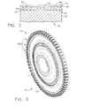
- FIG. 3 is a perspective view of a typical gas turbine engine disk 82 such as disk 36 or 40 of FIG. 1 , which is typically made of a superalloy material, such as one of the superalloy materials previously discussed.
- the disk 82 includes a hub 74 along typically the engine centerline that includes a bore through which a shaft (not shown) extends.
- the disk includes dovetail slots 86 along the disk outer periphery into which the turbine blades are inserted.
- a web section 78 of the disk 82 extends between the outer periphery, where the dovetail slots 86 are located, and the hub 74. While the present invention may be utilized anywhere along disk 82, including the dovetail slots 86, it finds particular use along the surfaces of web section 78 and the dovetail slots 86, which unlike the hub 74 is directly exposed to cooling air.
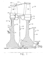
- FIG. 2 depicts, in cross-section, the coating 64 of the present invention in its simplest form, deposited on an engine component.
- Corrosion resistant coating 64 is deposited on the surface 62 of substrate 60.
- the substrate 60 may be a turbine engine disk such as first stage disk 36 or second stage disk 40.
- the substrate 60 may be a typical surface such as web section 78 of a turbine disk 82.
- substrate 60 comprising superalloy based on nickel, cobalt, iron and combinations thereof, has deposited thereon a coating 64 of the present invention.
- an undercoating may be provided (not shown), such as a MCrAlX coating, for example a NiCrAlY or a CoNiCrAlY an aluminide such as NiAl or noble metal-modified aluminide such as (Pt,Ni)Al.
- coating 64 can be cured as a single layer of graded coating and surface 66 is exposed to the cooling air forming the environment for the surface.
- coating 64 may be of substantially uniform composition. If the coating is to be graded, then additional layers are applied over coating layer 64, the first layer being applied over outer surface 66 and additional layers being applied over subsequent outer coating layers.
- metal surface 62 Prior to forming the corrosion resistant coating 64 of this invention on the surface 62 of metal substrate 60, metal surface 62 is typically pretreated mechanically, chemically or both to make the surface more receptive for coating 64.
- Suitable pretreatment methods include grit blasting, with or without masking of surfaces that are not to be subjected to grit blasting (see U.S. Patent No. 5,723,078 to Nagaraj et al., issued March 3, 1998 , especially col. 4, lines 46-66, which is incorporated by reference), micromachining, laser etching (see U.S. Patent No. 5,723,078 to Nagaraj et al., issued March 3, 1998 , especially col. 4, line 67 to col.
- the surface 62 of metal substrate 60 is pretreated by grit blasting where surface 62 is subjected to the abrasive action of silicon carbide particles, steel particles, alumina particles or other types of abrasive particles.
- These particles used in grit blasting are typically alumina particles and typically have a particle size of from about 600 to about 35 mesh (from about 25 to about 500 micrometers), more typically from about 360 to about 35 mesh (from about 35 to about 500 micrometers).
- the tape coating of the present invention is made by applying a slurry mixture of refractory particles, binder, plasticizer, and solvent to a tape film backing, followed by drying to form a tape coating a first surface in contact with the tape film backing and an exposed second surface opposite the first surface.
- the coating is applied to the film backing in thicknesses of from about 0.0001" (0.1mils) to about 0.005" (5 mils), and preferably in thicknesses from about 0.0005" (0.5 mils) to about 0.0025" (2.5 mils).
- the coating can be applied to such thicknesses as a single layer, or can be applied as a plurality of distinct layers to achieve a tape coating having an overall thickness of a preselected range.
- the coating composition is applied to the tape film backing and dried to form a tape coating.
- the exposed surface of the tape coating is applied to a surface of an engine component, the tape film backing is optionally removed, and the tape coating is then cured by application of heat to form a silica-based matrix having corrosion-resistant particles substantially uniformly dispersed throughout.
- Corrosion-resistance is provided by the corrosion-resistant particles (designated at "CR") comprising refractory particles (designated "RP") such as refractory oxides and nitrides, and non-refractory particles (designated "NRP”) such as MAl, MAlX, MCr, MCrX, MCrAlX, and combinations of these particles.
- CR corrosion-resistant particles
- RP refractory particles
- NPP non-refractory particles
- the silica-based matrix can be formulated in any one of a number of ways.
- a solvent-based system utilizes a silicone material that is mixed with a solvent (also referred to herein as a liquid carrier).
- a typical silicone material is SR-355 available from General Electric Silicones.
- An alternate silicone material is SR-350 available from General Electric Company, Wilton, Connecticut.
- the solvent typically an evaporable organic solvent, such as an alcohol (methanol, ethanol, propanol, etc), acetone or other suitable solvent is mixed to obtain a viscosity consistent with the preferred method of application, as will be discussed.
- the corrosion-resistant particles are added to the solvent and silicone material solution.
- These particles may include refractory particles that can impart corrosion-resistance to a coating such as, for example, alumina, yttrium oxide (Y205), zirconium oxide (Zr2O3), titanium oxide (TiO2), zironcia, hafnia, stabilized zirconia or hafnia (e.g.
- yttria stabilized or stabilized by other oxides - rare earths magnesia, calcia, scandia), ceria (CeO2), chromia (Cr2O3), iron oxide (Fe2O3, Fe3O4), titania (TiO2), yttria (Y2O3), YAG (Y3Al5O12), magnesia (MgO), and combinations thereof.
- the selected refractory material must fit the following two criteria to be acceptable: (1) the particle must have a CTE equal to or higher than alumina (alumina has a CTE of about 4 x 10⁻⁶ to about 5 x 10⁻⁶ in/in/F at 1200°F); and (2) must be more corrosion-resistant than the substrate, preferably substantially inert to corrosion.
- non-refractory particles are next added.
- exemplary non-refractory particles include MAl, MAlX, MCr, MCrX, and MCrAlX, and combinations thereof. After the corrosion-resistant particles have been added to the solution to form a slurry, at least one plasticizer is added and the slurry is mixed to substantial homogeneity.
- the viscosity is next adjusted by either adding or removing solvent to the mixture to yield a composition viscosity that is consistent with the intended method of application to the tape film backing. If the slurry is to be taped, the viscosity should be adjusted to be moderate, whereas if the slurry is to be applied as a spray, using for example, air assisted spray equipment to adjust the viscosity to very low, then liquid should be added so that the slurry is sprayable. Additionally, surfactants and dispersants may optionally be added to the slurry when required.
- the selection and amount of corrosion-resistant particles, binder, and solvent provide a coating composition that can be applied and cured to provide a corrosion-resistant coating layer having a predetermined CTE.
- the corrosion-resistant particles are added to the solvent and silicone so that the particles comprise from up to about 92% of the total solution by weight, the balance being the binder and solvent to render a composition that can be distributed onto a tape film backing, whether by spraying, casting, doctor-blading, spreading, or otherwise.
- the slurry contains from about 5% to about 45% binder, from about 3% to about 50% solvent and from about 15% to about 92% refractory particles, and from about 3 to about 35% plasticizer by weight.
- the slurry contains from about 5% to about 45% binder, from about 3% to about 50% solvent, from about 10% to about 87% non-refractory particles and from about 5% to about 82% refractory particles, and from about 5 to about 35% plasticizer by weight.
- the corrosion resistant particles are provided in a size range of 25 microns and smaller.
- the particles are 10 microns and smaller in size.
- the particles may be substantially equiaxed (spherical) or non-equiaxed (flake).
- the particles should be provided in at least two sizes. In such a circumstance, the average particle size preferably should differ by a factor of about 7 to 10. The size difference between the particles allows the smaller particles to fill the areas between the larger particles. This is particularly evident when the particles are substantially equiaxed.
- a second size range of particles should also be included wherein the particles are 0.5 microns and smaller.
- the coating composition mixture is thoroughly agitated. Agitation can be accomplished by any convenient method for about 0.1-5 hours. Preferably, mixing is accomplished for a period of about 0.1-0.5 hours. This is an important step, for it is not only important that the particles be substantially uniformly and thoroughly distributed throughout the slurry, it is also important that the solution completely "wet" or coat the particles. Depending on the particles, it is believed that the surfaces of the particles may become hydrolyzed which, as will be discussed, will allow bonding with the silica-based material.
- the viscosity is adjusted so that the slurry can be applied to the tape film backing by tape casting.
- the slurry is continuously agitated by placing a stirrer into the mix until it is ready for application. Even as the slurry is taped onto the tape film backing, the slurry can be pneumatically agitated by using a stirrer.
- the coating composition is applied to the film tape backing to a preselected thickness using a doctor blade or tape casting equipment.
- the coating system may be sprayed onto the tape film backing to form one or more tape ceramic layers on the tape film backing, yielding a tape coating of preselected thickness.
- the applied composition is allowed to dry. Drying is typically accomplished in two steps. In the first step, drying is accomplished to remove unbound solvent. This is accomplished after application of the composition to the surface of the component by raising the temperature to less than 212°F (100°C). It will be recognized by those skilled in the art that higher humidities and/or lower temperatures will also provide drying, but will require longer times to achieve the necessary drying. When the coating is applied to a thickness of about 0.001" (one mil) or greater, heating must be accomplished at a rate of no greater than about 2-10°F/min. to prevent blistering.
- the tape coating is applied to the surface of an article to be coated.
- the exposed surface of the tape coating composition is placed in contact with the surface of the component to be coated, and pressure is applied to the tape backing.
- the tape backing is then optionally removed, leaving the coating composition on the surface of the component.
- the tape backing may be removed by any means, such as by manual or automated peeling, chemical dissolving or chemical reaction, or by thermal degradation.
- the tape film backing is not immediately removed, it may be later removed by any of the above removal processes or by other known methods.
- heat is applied to the coating to effect an initial cure, such as by heating the component, preferably to a temperature of at least 400°F.
- pressure may also be exerted, preferably simultaneously with the step of heating, to initially cure and securely adhere the coating to the substrate.
- the coated substrate is fired to an elevated temperature to convert the coating into a glass or a glassy ceramic with substantially uniformly dispersed particles throughout.
- firing is accomplished at a temperature at or above the expected operating temperature of the component, but not less than about 700°F.
- the coating may be fired up to about 2100°F. The higher the firing temperature, the higher percentage of the glass that is converted from glass to ceramic.
- a graded coating may be achieved by applying additional layers over the first layer and subsequent layers, each subsequent layer applied after drying to remove unbound water and optionally fired to cure the layer. Of course, each layer is adjusted to have a different loading of particles and or particles of different compositions, the loading and type of particles determining the CTE of the layer.
- the graded coating is applied in this manner, there may be some mixing of the loadings at the interface between layers. On curing, there will be strong chemical bonding between the layers, and except for the loadings, the "layer" aspect will disappear and the coating will act as a uniform coating. Since the CTE can be tailored with thickness, the resulting stresses and strains can be designed as a function of coating thickness. This permits, if desired, the use of a highly corrosion resistant, low CTE particle such as alumina, in a coating layer, which layer can be applied over a higher CTE coating layer, such as a layer that includes CoNiCrAlY particles without negatively affecting the adhesion of the coating to the substrate.
- additional mixed layers of the coating composition may be applied as overcoats to transition from high CTE at the substrate to lower CTE at the surface of the coated article.
- each subsequent layer is applied after drying to remove bound water and commence an initial cure.
- each layer is adjusted to have a different loading of particles, the loading of particles determining the CTE of the layer. For example, adjusting the ratio of refractory particles such as alumina and non-refractory particles such as CoNiCrAlY will alter the STE of a given coating layer.
- the graded coating is applied in this manner, there is substantially no mixing of the loadings at the interface between layers and the layers are distinct.
- the corrosion resistant particulates comprise only refractory particles, in this case SM8 alumina and A17SG alumina.
- refractory particles may be utilized, and preferably are provided in at least two particle size ranges, as further described herein.
- the corrosion resistant particulates comprise both refractory and non-refractory particles.
- the non-refractory particulate may be FeAl, an iron-based alloy comprising Fe and having about 10 weight percent aluminum.
- An exemplary FeAl is produced by Praxair Surface Technologies and is designated as Fe-125.
- Fe-125 is reported to have an average particle size of less than about 27 microns.
- Fe-125 may be further screened to have an average particle size of less than about 5 microns.
- SM8 alumina may be provided as a refractory particulate.
- refractory and non-refractory particulates many be used, such as CO-210-6 (CoNiCrAlY alloy powder), A16SG alumina, A17SG alumina, nano-alumina, and combinations thereof, as further described herein.
- the anti-corrosive particulates in the above prophetic examples each include at least one corrosion-resistant particle selected to have a CTE equal to or greater than alumina, thus providing the coating with a CTE equal to or greater than that of alumina at engine operating temperatures.
- Such particulates can be any refractory oxide, nitride, carbide, metal or alloy having a CTE greater than that of alumina.
- the non-refractory corrosion resistant particulate is an iron-based alloy, nickel-based alloy, a cobalt-based alloy, an MCr, MCrX, MAl, MAlX or MCrAlY, or any combination thereof.
- CO-210-6 an atomized powder alloy comprised of about 38.5 weight percent cobalt, 32 weight percent nickel, 21 weight percent chromium, 8 weight percent aluminum, and 0.50 weight percent yttrium.
- CO-210-6 is a designated trade name of, and is commercially available from, Praxair Surface Technologies, Inc. of Indianapolis, IN, USA.
- CO-210-6 is further specified as having an agglomerate size distribution (on a cumulative weight basis) of a maximum of about 5 percent below 1.94 microns, about 50 percent between 5 to 7 microns, a minimum of about 95 percent below 16 microns, and 100 percent below 22 microns.
- CO-210-6 and other non-alumina alloys may be provided in a number of different particle size ranges, and also having various weight percentages of the metals falling within the above-described broad specification. Additionally, while CO-210-6 is preferred, other alloys having similar CTE characteristics (i.e. CTE characteristics that are not identical to alumina) are also suitable for use in the coating composition of the present invention.
- a refractory oxide is also provided as an anti-corrosive particulate in the exemplary compositions.
- the refractory oxide is alumina, and more preferably comprises alumina in at least two particle sizes.
- the alumina particulate includes a first alumina constituent having number average particle size (diameter) of between 0.05 and 0.8 micrometers, more preferably between 0.10 and 0.6 micrometers, for example, having an average particle size of 0.15 micrometers.
- a suitable first alumina constituent is commercially available from Baikowski International Corporation under the trademark Baikalox SM8 (hereinafter "SM8") having 99.99 percent A12O3, by weight, specific surface areas BET square meters per gram of 10+/-1, a major phase of alpha, 95 percent major phase, a crystal density of 3.98 grams per square centimeter, a bulk density of 0.93 grams per cubic centimeter, a pressed density of 1.85 grams per cubic centimeter at 2200 psi, and an agglomerate size distribution on a cumulative weight basis of 65 weight percent being ⁇ 0.3 micrometer, 78 percent being ⁇ 0.4 micrometer, 90 percent being ⁇ 0.5 micrometers, 95 percent being ⁇ 0.6 micrometers, and 100 percent being less than 1.0 micrometers, and having about 8 ppm Na, 3 5 ppm K, 3 5 ppm Si, 6 ppm V and 3 ppm Ca.
- SM8 Baikalox SM8
- the refractory fraction of the anti-corrosive particulates further includes more than one refractory constituent having a number average particle size (diameter) of less than 25 microns.
- a suitable second refractory particle product is alumina commercially available from Almatis under the trade names A16SG and A17SG (hereinafter "A16SG" and "A17SG”).
- A16SG and A17SG are reported by the manufacturer as having a low soda content (NaO 2 of ⁇ 0.10 percent), a surface area of about 8.2 or 2.5 m.2 /g and a median particle size of about 0.48 and 2.9 microns, respectively.
- the binder is preferably a silicone binder, and is more preferably a polymethyl siloxane binder.
- a suitable silicone binder is SR355 by General Electric Co., classified as a methylsesquisiloxane mixture of the polysiloxane family having a specific gravity of 1.05 to 1.10, a bulk density of 1.02 to 1.14 grams per cubic centimeter, a maximum gel percent of 0.3, and a melt viscosity of 400 to 2000 cps.
- the silicone resins may be represented by the formula set forth in U.S. Patent No.
- R', R, and R" are preferably selected from alkyl groups, and n is preferably selected from 1-1000, for example, from 1 to 500.
- Another suitable silicone binder is SR350 by General Electric Co., also classified as methylsesquisiloxane mixture of the polysiloxane family.
- the amount of SR350 silicone binder indicated in Table I will yield silica particles in an amount of about 60 to about 75 weight percent of the original amount of SR350 silicone binder present in the tape composition.
- a like amount of the SR355 silicone binder is capable of yielding silica particles in an amount of about 30 to about 40 weight percent of the original amount of SR355 silicone binder present in the tape composition.
- Plasticizers include commercially available organic plasticizers such as that marketed as Butvar B79 by Monsanto, a proprietary organic plasticizer, as well as that plasticizer marketed as Santicizer 160 by Monsanto, specified as a butyl phthalate plasticizer by the manufacturer.
- plasticizers which may be used in the present invention include dioctyl phthalate (DOP) dibutyl phthalate (DBP); disctyl adipate isodecyl malonate; diethylene glycol dibenzoate, pentaerythritol ester; butyl oleate, methyl acetylricinoleate; tricresyl phosphate and trioctyl phosphate; polypropylene glycol adipate and polybutylene glycol adipate; and the like. These plasticizers may be used along or in combination of two or more.
- the solvent comprises an alcohol such as methanol, ethanol, propanol, or combination thereof, although other polar organic solvents such as acetone or trichloroethylene could additionally or alternatively be used. More preferably, the solvent comprises anhydrous alcohol. Most preferably, the solvent comprises about 95 weight percent ethyl alcohol and about 5 weight percent isopropyl alcohol.
- Surfactants are optionally included.
- a suitable surfactant is that commercially available surfactant marketed as PS21A Whitco Chemical.
- PS21A is specified as an alkyl organic phosphate ester acid surfactant by the manufacturer, and is believed to promote wetting of the alumina particles and/or other refractory particles of the composition.
- Any surfactants preferably comprise less than 1 weight percent of the composition.
- the composition After being applied onto a tape film backing using any suitable doctor blade known in the art, the composition can be dried at room temperature to form a tape coating. After drying, the composition may be applied to substrate and then fired to yield a substantially homogeneous protective coating. Suitable thicknesses for the coating deposited by the tape method are in a range of about 0.1 mil to about 5 mils, and more preferably between about 0.5 mils and 2.5 mils.
- the protective coating 64 is formed by applying tape coatings of a suitable thickness and composition to the substrate 60.
- the tape coating can generally be formed by casting the same constituents disclosed above.
- a surfactant is preferably included to promote wetting of the solids by the liquid components of the coating composition, and a plasticizer is present to yield solid tape coatings that, upon drying, can be handled and applied as a tape coating.
- the tape coatings are preferably applied in layers, one over the other. In a preferred embodiment, tape coatings having different compositions are applied, so that after firing, the coating 64 has inner and outer layers with different compositions.
- tapes used to form the inner layer of the coating 64 may contain an additional ceramic powder constituent, such as a glass frit or zirconia, preferably YSZ, for improving the thermal expansion stress distribution through the coating 64.
- an additional ceramic powder constituent such as a glass frit or zirconia, preferably YSZ, for improving the thermal expansion stress distribution through the coating 64.
Landscapes
- Chemical & Material Sciences (AREA)
- Engineering & Computer Science (AREA)
- Inorganic Chemistry (AREA)
- Materials Engineering (AREA)
- Mechanical Engineering (AREA)
- Chemical Kinetics & Catalysis (AREA)
- Metallurgy (AREA)
- Organic Chemistry (AREA)
- General Engineering & Computer Science (AREA)
- Ceramic Engineering (AREA)
- Other Surface Treatments For Metallic Materials (AREA)
- Turbine Rotor Nozzle Sealing (AREA)
Applications Claiming Priority (1)
| Application Number | Priority Date | Filing Date | Title |
|---|---|---|---|
| US11/616,048 US20090098394A1 (en) | 2006-12-26 | 2006-12-26 | Strain tolerant corrosion protecting coating and tape method of application |
Publications (2)
| Publication Number | Publication Date |
|---|---|
| EP1939325A2 true EP1939325A2 (fr) | 2008-07-02 |
| EP1939325A3 EP1939325A3 (fr) | 2011-08-03 |
Family
ID=39129058
Family Applications (1)
| Application Number | Title | Priority Date | Filing Date |
|---|---|---|---|
| EP07122504A Withdrawn EP1939325A3 (fr) | 2006-12-26 | 2007-12-06 | Revêtement de protection de corrosion tolérant en contrainte et procédé d'application par bande |
Country Status (3)
| Country | Link |
|---|---|
| US (1) | US20090098394A1 (fr) |
| EP (1) | EP1939325A3 (fr) |
| JP (1) | JP2008202141A (fr) |
Cited By (2)
| Publication number | Priority date | Publication date | Assignee | Title |
|---|---|---|---|---|
| WO2011041026A1 (fr) * | 2009-09-30 | 2011-04-07 | General Electric Company | Compositions pour revêtement de protection contre la corrosion et tolérant à la contrainte et articles pourvus de ce revêtement |
| EP2842662A1 (fr) * | 2013-09-03 | 2015-03-04 | MTU Aero Engines GmbH | Blindage de pointe pour des aubes en titane |
Families Citing this family (9)
| Publication number | Priority date | Publication date | Assignee | Title |
|---|---|---|---|---|
| JP5112286B2 (ja) * | 2008-12-26 | 2013-01-09 | 株式会社東芝 | 蒸気タービン翼及び蒸気タービン |
| US20110076410A1 (en) * | 2009-09-30 | 2011-03-31 | Andrew Jay Skoog | Method for making strain tolerant corrosion protective coating compositions and coated articles |
| US9598775B2 (en) * | 2011-06-13 | 2017-03-21 | Praxair S.T. Technology, Inc. | Multilayer overlay system for thermal and corrosion protection of superalloy substrates |
| DE102011081112A1 (de) * | 2011-08-17 | 2013-02-21 | Rolls-Royce Deutschland Ltd & Co Kg | Verfahren zur Herstellung eines Bauteils für hohe thermische Belastungen, ein Bauteil herstellbar mit dem Verfahren und ein Flugzeugtriebwerk mit dem Bauteil |
| DE102014222024A1 (de) | 2014-10-29 | 2016-06-16 | MTU Aero Engines AG | Schlicker und Verfahren zur Herstellung einer Oxidations- und Korrosionsbeständigen Diffusionschicht |
| JP6962334B2 (ja) * | 2016-12-07 | 2021-11-05 | 日本電気株式会社 | 監視方法、監視システム、および、構造物、建築物または移動体 |
| US10454114B2 (en) | 2016-12-22 | 2019-10-22 | The Research Foundation For The State University Of New York | Method of producing stable, active and mass-producible Pt3Ni catalysts through preferential co etching |
| WO2020191363A1 (fr) * | 2019-03-21 | 2020-09-24 | University Of Connecticut | Élément de combustion revêtu issu d'une projection thermique de précurseur liquide |
| US11415004B2 (en) * | 2020-12-09 | 2022-08-16 | Honeywell International Inc. | Corrosion and oxidation resistant coatings for gas turbine engines, and methods for producing the same |
Citations (13)
| Publication number | Priority date | Publication date | Assignee | Title |
|---|---|---|---|---|
| US4353780A (en) | 1980-10-01 | 1982-10-12 | United Technologies Corporation | Chemical milling of high tungsten content superalloys |
| US4411730A (en) | 1980-10-01 | 1983-10-25 | United Technologies Corporation | Selective chemical milling of recast surfaces |
| US4544408A (en) | 1983-04-18 | 1985-10-01 | Sermatech International Inc. | Thixotropic alumina coating compositions, parts and methods |
| US4563239A (en) | 1984-10-16 | 1986-01-07 | United Technologies Corporation | Chemical milling using an inert particulate and moving vessel |
| US4606967A (en) | 1983-10-19 | 1986-08-19 | Sermatech International Inc. | Spherical aluminum particles in coatings |
| US4617056A (en) | 1983-12-29 | 1986-10-14 | Sermatech International, Inc. | Thick coating compositions |
| US5368888A (en) | 1991-11-04 | 1994-11-29 | General Electric Company | Apparatus and method for gas phase coating of hollow articles |
| US5723078A (en) | 1996-05-24 | 1998-03-03 | General Electric Company | Method for repairing a thermal barrier coating |
| US6210791B1 (en) | 1995-11-30 | 2001-04-03 | General Electric Company | Article with a diffuse reflective barrier coating and a low-emissity coating thereon, and its preparation |
| US6283715B1 (en) | 1999-08-11 | 2001-09-04 | General Electric Company | Coated turbine component and its fabrication |
| US6544351B2 (en) | 2001-07-12 | 2003-04-08 | General Electric Company | Compositions and methods for producing coatings with improved surface smoothness and articles having such coatings |
| US20040013802A1 (en) | 2002-07-19 | 2004-01-22 | Ackerman John Frederick | Protection of a gas turbine component by a vapor-deposited oxide coating |
| US20060127694A1 (en) | 2004-12-15 | 2006-06-15 | Hazel Brian T | Corrosion resistant coating composition, coated turbine component and method for coating same |
Family Cites Families (20)
| Publication number | Priority date | Publication date | Assignee | Title |
|---|---|---|---|---|
| US3725186A (en) * | 1970-11-25 | 1973-04-03 | Nat Beryllia Corp | Composite ceramic articles |
| US4046612A (en) * | 1975-03-05 | 1977-09-06 | Gte Sylvania Incorporated | Method for producing a bilayered green ceramic tape |
| SE7906404L (sv) * | 1978-08-28 | 1980-02-29 | Aikoh Co | Lansror |
| US4376004A (en) * | 1979-01-16 | 1983-03-08 | Westinghouse Electric Corp. | Method of manufacturing a transpiration cooled ceramic blade for a gas turbine |
| US4344556A (en) * | 1979-05-29 | 1982-08-17 | Knapp Donald K | Welding backup tape and its method of manufacture |
| US4608128A (en) * | 1984-07-23 | 1986-08-26 | General Electric Company | Method for applying abrasive particles to a surface |
| US4773928A (en) * | 1987-08-03 | 1988-09-27 | Gte Products Corporation | Plasma spray powders and process for producing same |
| US5278138A (en) * | 1990-04-16 | 1994-01-11 | Ott Kevin C | Aerosol chemical vapor deposition of metal oxide films |
| US5505248A (en) * | 1990-05-09 | 1996-04-09 | Lanxide Technology Company, Lp | Barrier materials for making metal matrix composites |
| US5858465A (en) * | 1993-03-24 | 1999-01-12 | Georgia Tech Research Corporation | Combustion chemical vapor deposition of phosphate films and coatings |
| US5902429A (en) * | 1995-07-25 | 1999-05-11 | Westaim Technologies, Inc. | Method of manufacturing intermetallic/ceramic/metal composites |
| US6248392B1 (en) * | 1996-12-20 | 2001-06-19 | Nederlandse Organisatie Voor Toegepast-Natuurwetenschappelijk Ondersoek Tno | Method for manufacturing a fiber-reinforced bioactive ceramic implant |
| US6005446A (en) * | 1997-10-01 | 1999-12-21 | Raytheon Company | Microwave frequency synthesizer |
| DE19807636C1 (de) * | 1998-02-23 | 1999-11-18 | Mtu Muenchen Gmbh | Verfahren zum Herstellen einer korrosions- und oxidationsbeständigen Schlickerschicht |
| US6165600A (en) * | 1998-10-06 | 2000-12-26 | General Electric Company | Gas turbine engine component having a thermal-insulating multilayer ceramic coating |
| US6756139B2 (en) * | 2002-03-28 | 2004-06-29 | The Regents Of The University Of California | Buffer layers on metal alloy substrates for superconducting tapes |
| US6884527B2 (en) * | 2003-07-21 | 2005-04-26 | The Regents Of The University Of California | Biaxially textured composite substrates |
| US7588797B2 (en) * | 2004-04-07 | 2009-09-15 | General Electric Company | Field repairable high temperature smooth wear coating |
| US20070128447A1 (en) * | 2005-12-02 | 2007-06-07 | General Electric Company | Corrosion inhibiting ceramic coating and method of application |
| US7754342B2 (en) * | 2005-12-19 | 2010-07-13 | General Electric Company | Strain tolerant corrosion protecting coating and spray method of application |
-
2006
- 2006-12-26 US US11/616,048 patent/US20090098394A1/en not_active Abandoned
-
2007
- 2007-12-06 EP EP07122504A patent/EP1939325A3/fr not_active Withdrawn
- 2007-12-12 JP JP2007320254A patent/JP2008202141A/ja not_active Withdrawn
Patent Citations (14)
| Publication number | Priority date | Publication date | Assignee | Title |
|---|---|---|---|---|
| US4353780A (en) | 1980-10-01 | 1982-10-12 | United Technologies Corporation | Chemical milling of high tungsten content superalloys |
| US4411730A (en) | 1980-10-01 | 1983-10-25 | United Technologies Corporation | Selective chemical milling of recast surfaces |
| US4544408A (en) | 1983-04-18 | 1985-10-01 | Sermatech International Inc. | Thixotropic alumina coating compositions, parts and methods |
| US4606967A (en) | 1983-10-19 | 1986-08-19 | Sermatech International Inc. | Spherical aluminum particles in coatings |
| US4617056A (en) | 1983-12-29 | 1986-10-14 | Sermatech International, Inc. | Thick coating compositions |
| US4563239A (en) | 1984-10-16 | 1986-01-07 | United Technologies Corporation | Chemical milling using an inert particulate and moving vessel |
| US5368888A (en) | 1991-11-04 | 1994-11-29 | General Electric Company | Apparatus and method for gas phase coating of hollow articles |
| US6210791B1 (en) | 1995-11-30 | 2001-04-03 | General Electric Company | Article with a diffuse reflective barrier coating and a low-emissity coating thereon, and its preparation |
| US5723078A (en) | 1996-05-24 | 1998-03-03 | General Electric Company | Method for repairing a thermal barrier coating |
| US6283715B1 (en) | 1999-08-11 | 2001-09-04 | General Electric Company | Coated turbine component and its fabrication |
| US6544351B2 (en) | 2001-07-12 | 2003-04-08 | General Electric Company | Compositions and methods for producing coatings with improved surface smoothness and articles having such coatings |
| US20040013802A1 (en) | 2002-07-19 | 2004-01-22 | Ackerman John Frederick | Protection of a gas turbine component by a vapor-deposited oxide coating |
| US20060127694A1 (en) | 2004-12-15 | 2006-06-15 | Hazel Brian T | Corrosion resistant coating composition, coated turbine component and method for coating same |
| EP1672174A1 (fr) | 2004-12-15 | 2006-06-21 | General Electric Company | Composition de revêtement anticorrosif, composants de turbine revêtu et son procèdè de fabrication |
Cited By (2)
| Publication number | Priority date | Publication date | Assignee | Title |
|---|---|---|---|---|
| WO2011041026A1 (fr) * | 2009-09-30 | 2011-04-07 | General Electric Company | Compositions pour revêtement de protection contre la corrosion et tolérant à la contrainte et articles pourvus de ce revêtement |
| EP2842662A1 (fr) * | 2013-09-03 | 2015-03-04 | MTU Aero Engines GmbH | Blindage de pointe pour des aubes en titane |
Also Published As
| Publication number | Publication date |
|---|---|
| EP1939325A3 (fr) | 2011-08-03 |
| US20090098394A1 (en) | 2009-04-16 |
| JP2008202141A (ja) | 2008-09-04 |
Similar Documents
| Publication | Publication Date | Title |
|---|---|---|
| US7754342B2 (en) | Strain tolerant corrosion protecting coating and spray method of application | |
| EP1939325A2 (fr) | Revêtement de protection de corrosion tolérant en contrainte et procédé d'application par bande | |
| US20070128447A1 (en) | Corrosion inhibiting ceramic coating and method of application | |
| US7776143B2 (en) | Particulate corrosion resistant coating composition | |
| EP1870493A2 (fr) | Revêtement tolérant en contrainte pour protection environnementale | |
| US7666528B2 (en) | Protection of thermal barrier coating by a sacrificial coating | |
| US20090047135A1 (en) | Layered corrosion resistant coating for turbine blade environmental protection | |
| US7666515B2 (en) | Turbine component other than airfoil having ceramic corrosion resistant coating and methods for making same | |
| US7314674B2 (en) | Corrosion resistant coating composition, coated turbine component and method for coating same | |
| EP1927675A1 (fr) | Revêtement céramique résistant à la corrosion pour la résistance à l'oxydation | |
| JP2002256452A (ja) | 遮熱コーティングの補修方法並びに当該方法で形成された補修コーティング | |
| EP3819399A1 (fr) | Système et procédé de revêtement par restauration | |
| US20110076410A1 (en) | Method for making strain tolerant corrosion protective coating compositions and coated articles | |
| US20110076480A1 (en) | Strain tolerant corrosion protective coating compositions and coated articles | |
| CN115873498A (zh) | 耐腐蚀涂料 | |
| US20250257694A1 (en) | Gas turbine engine |
Legal Events
| Date | Code | Title | Description |
|---|---|---|---|
| PUAI | Public reference made under article 153(3) epc to a published international application that has entered the european phase |
Free format text: ORIGINAL CODE: 0009012 |
|
| AK | Designated contracting states |
Kind code of ref document: A2 Designated state(s): AT BE BG CH CY CZ DE DK EE ES FI FR GB GR HU IE IS IT LI LT LU LV MC MT NL PL PT RO SE SI SK TR |
|
| AX | Request for extension of the european patent |
Extension state: AL BA HR MK RS |
|
| RIN1 | Information on inventor provided before grant (corrected) |
Inventor name: DOYLE, TIMOTHY A. Inventor name: WEIMER, MICHAEL JAMES Inventor name: MURPHY, JANE ANN Inventor name: HAZEL, BRIAN THOMAS Inventor name: BOJANOVSKI, BRYAN Inventor name: SKOOG, ANDREW JAY |
|
| PUAL | Search report despatched |
Free format text: ORIGINAL CODE: 0009013 |
|
| AK | Designated contracting states |
Kind code of ref document: A3 Designated state(s): AT BE BG CH CY CZ DE DK EE ES FI FR GB GR HU IE IS IT LI LT LU LV MC MT NL PL PT RO SE SI SK TR |
|
| AX | Request for extension of the european patent |
Extension state: AL BA HR MK RS |
|
| RIC1 | Information provided on ipc code assigned before grant |
Ipc: F01D 5/28 20060101ALI20110628BHEP Ipc: C23C 28/00 20060101ALI20110628BHEP Ipc: C23C 26/00 20060101AFI20110628BHEP |
|
| AKY | No designation fees paid | ||
| REG | Reference to a national code |
Ref country code: DE Ref legal event code: R108 Effective date: 20120411 |
|
| STAA | Information on the status of an ep patent application or granted ep patent |
Free format text: STATUS: THE APPLICATION IS DEEMED TO BE WITHDRAWN |
|
| 18D | Application deemed to be withdrawn |
Effective date: 20120204 |