EP1939378A2 - Schließvorrichtung zum Verriegeln des Innenraums eines Gerätes und Gerät mit Schließvorrichtung - Google Patents
Schließvorrichtung zum Verriegeln des Innenraums eines Gerätes und Gerät mit Schließvorrichtung Download PDFInfo
- Publication number
- EP1939378A2 EP1939378A2 EP07117335A EP07117335A EP1939378A2 EP 1939378 A2 EP1939378 A2 EP 1939378A2 EP 07117335 A EP07117335 A EP 07117335A EP 07117335 A EP07117335 A EP 07117335A EP 1939378 A2 EP1939378 A2 EP 1939378A2
- Authority
- EP
- European Patent Office
- Prior art keywords
- closing
- bolt
- locking
- latch
- signal
- Prior art date
- Legal status (The legal status is an assumption and is not a legal conclusion. Google has not performed a legal analysis and makes no representation as to the accuracy of the status listed.)
- Granted
Links
Images


Classifications
-
- E—FIXED CONSTRUCTIONS
- E05—LOCKS; KEYS; WINDOW OR DOOR FITTINGS; SAFES
- E05B—LOCKS; ACCESSORIES THEREFOR; HANDCUFFS
- E05B47/00—Operating or controlling locks or other fastening devices by electric or magnetic means
- E05B47/02—Movement of the bolt by electromagnetic means; Adaptation of locks, latches, or parts thereof, for movement of the bolt by electromagnetic means
-
- F—MECHANICAL ENGINEERING; LIGHTING; HEATING; WEAPONS; BLASTING
- F25—REFRIGERATION OR COOLING; COMBINED HEATING AND REFRIGERATION SYSTEMS; HEAT PUMP SYSTEMS; MANUFACTURE OR STORAGE OF ICE; LIQUEFACTION SOLIDIFICATION OF GASES
- F25D—REFRIGERATORS; COLD ROOMS; ICE-BOXES; COOLING OR FREEZING APPARATUS NOT OTHERWISE PROVIDED FOR
- F25D27/00—Lighting arrangements
- F25D27/005—Lighting arrangements combined with control means
-
- F—MECHANICAL ENGINEERING; LIGHTING; HEATING; WEAPONS; BLASTING
- F25—REFRIGERATION OR COOLING; COMBINED HEATING AND REFRIGERATION SYSTEMS; HEAT PUMP SYSTEMS; MANUFACTURE OR STORAGE OF ICE; LIQUEFACTION SOLIDIFICATION OF GASES
- F25D—REFRIGERATORS; COLD ROOMS; ICE-BOXES; COOLING OR FREEZING APPARATUS NOT OTHERWISE PROVIDED FOR
- F25D29/00—Arrangement or mounting of control or safety devices
- F25D29/003—Arrangement or mounting of control or safety devices for movable devices
-
- E—FIXED CONSTRUCTIONS
- E05—LOCKS; KEYS; WINDOW OR DOOR FITTINGS; SAFES
- E05B—LOCKS; ACCESSORIES THEREFOR; HANDCUFFS
- E05B47/00—Operating or controlling locks or other fastening devices by electric or magnetic means
- E05B2047/0048—Circuits, feeding, monitoring
- E05B2047/0067—Monitoring
- E05B2047/0069—Monitoring bolt position
-
- E—FIXED CONSTRUCTIONS
- E05—LOCKS; KEYS; WINDOW OR DOOR FITTINGS; SAFES
- E05B—LOCKS; ACCESSORIES THEREFOR; HANDCUFFS
- E05B47/00—Operating or controlling locks or other fastening devices by electric or magnetic means
- E05B2047/0072—Operation
- E05B2047/0073—Current to unlock only
- E05B2047/0074—Current to unlock only holding means other than current (mechanical, magnetic)
-
- E—FIXED CONSTRUCTIONS
- E05—LOCKS; KEYS; WINDOW OR DOOR FITTINGS; SAFES
- E05B—LOCKS; ACCESSORIES THEREFOR; HANDCUFFS
- E05B47/00—Operating or controlling locks or other fastening devices by electric or magnetic means
- E05B47/0001—Operating or controlling locks or other fastening devices by electric or magnetic means with electric actuators; Constructional features thereof
- E05B47/0002—Operating or controlling locks or other fastening devices by electric or magnetic means with electric actuators; Constructional features thereof with electromagnets
-
- E—FIXED CONSTRUCTIONS
- E05—LOCKS; KEYS; WINDOW OR DOOR FITTINGS; SAFES
- E05B—LOCKS; ACCESSORIES THEREFOR; HANDCUFFS
- E05B65/00—Locks or fastenings for special use
- E05B65/0042—For refrigerators or cold rooms
-
- E—FIXED CONSTRUCTIONS
- E05—LOCKS; KEYS; WINDOW OR DOOR FITTINGS; SAFES
- E05C—BOLTS OR FASTENING DEVICES FOR WINGS, SPECIALLY FOR DOORS OR WINDOWS
- E05C3/00—Fastening devices with bolts moving pivotally or rotatively
- E05C3/12—Fastening devices with bolts moving pivotally or rotatively with latching action
- E05C3/16—Fastening devices with bolts moving pivotally or rotatively with latching action with operating handle or equivalent member moving otherwise than rigidly with the latch
- E05C3/22—Fastening devices with bolts moving pivotally or rotatively with latching action with operating handle or equivalent member moving otherwise than rigidly with the latch the bolt being spring controlled
- E05C3/30—Fastening devices with bolts moving pivotally or rotatively with latching action with operating handle or equivalent member moving otherwise than rigidly with the latch the bolt being spring controlled in the form of a hook
-
- Y—GENERAL TAGGING OF NEW TECHNOLOGICAL DEVELOPMENTS; GENERAL TAGGING OF CROSS-SECTIONAL TECHNOLOGIES SPANNING OVER SEVERAL SECTIONS OF THE IPC; TECHNICAL SUBJECTS COVERED BY FORMER USPC CROSS-REFERENCE ART COLLECTIONS [XRACs] AND DIGESTS
- Y10—TECHNICAL SUBJECTS COVERED BY FORMER USPC
- Y10T—TECHNICAL SUBJECTS COVERED BY FORMER US CLASSIFICATION
- Y10T70/00—Locks
- Y10T70/70—Operating mechanism
- Y10T70/7051—Using a powered device [e.g., motor]
- Y10T70/7062—Electrical type [e.g., solenoid]
- Y10T70/7102—And details of blocking system [e.g., linkage, latch, pawl, spring]
Definitions
- the invention relates to a locking device for locking the interior of a device, wherein the interior is usually closed with a closing element, such as a door, a slide, a flap, a roller shutter or the like.
- a closing element such as a door, a slide, a flap, a roller shutter or the like.
- Such locking devices are particularly needed in domestic appliances or household appliances in which no access to the interior by operators is to be obtained during operation, such as washing machines, microwaves, dishwashers or similar devices. Either there are dangers for the operator when opening the device during operation, for example, or the equipment may leak into the environment.
- a special need for locking devices also exists when devices are used in dynamic environments, such as on ships, airplanes, trains, or recreational vehicles.
- recreational vehicles in this context are both caravans as well as self-propelled motor caravans and watercraft (such as Y-Eighth) to understand.
- Such locking devices have the disadvantage that they must be mechanically operated and that appropriate release mechanisms must be provided, which operate the locking hook. Furthermore, the release mechanisms for the locking devices must be designed constructively so that they take into account different sides of the doors of household appliances.
- a locking device is known in which a holding device is arranged in the region of a lock for a domestic appliance, which can be locked by means of an electromagnet and a sliding circuit. A closing hook, which is provided at an example door, it is then no longer possible to exit from the holding element, because this is blocked.
- a locking device a bolt which engages in a holding element which is arranged on a closing element.
- the retaining element has no projecting parts, and therefore the locking device is exposed to frequent opening and closing no mechanical stress.
- the locking device according to the invention advantageously has an electromagnet which actuates the bolt. This type of operation is mechanically simpler than the prior art and therefore more reliable because it dispenses with surplus mechanical elements.
- a development of the locking device according to the invention comprises a detector with which the orientation of the bolt is detected, which switches a bolt signal. In this way it can be determined via a remote evaluation, whether the locking device is locked, or whether it is open.
- the bolt is arranged on a crankshaft, wherein the crank is mechanically biased, so that advantageously the two orientations of the bolt are mechanically stabilized.
- the transition between the two orientations of the bolt is effected via a switching rocker, wherein the switching rocker is actuated directly or indirectly by an electromagnet.
- a switching rocker is actuated directly or indirectly by an electromagnet.
- Such a device is mechanically very reliable. This is also known, for example, from the ballpoint actuator.
- a second detector for detecting the presence of the holding element, which switches a closing signal is particularly advantageously arranged on the device. In this way it can be determined reliably advantageous whether the closing element, that is the door, is closed or opened. This information can be used for remote diagnostics, for a safety shutdown or alarm, for controlling interior lighting, and for switching defined closing conditions also defined in connection with the lock signal.
- the closing device according to the invention in the region of the closing device, it is particularly advantageous to arrange a lighting device which is switched via the closing signal. In this way, can be dispensed with an additional wiring for the lighting, and the closing signal can be used in addition to the switching of the lighting device.
- the electromagnet can be triggered from outside, so that, for example, remote locking or unlocking of the locking device can be triggered, for example, from a driver's cabin of a motorhome, or the locking device can be unlocked by a switch is provided in an area that is also accessible to children, for example.
- the solenoid is controlled in response to the latch signal and the closing signal, it can be advantageously ensured that the latch is triggered only when the closing element, that is, the door is closed, or It can be ensured when locking the device and the door open that a closing operation can be easily performed, even if a mechanical rigid locking is provided.
- the electromagnet is controlled via an ignition on signal of a motor vehicle, it can be advantageously ensured when starting for example a motorhome that the refrigerator, for example, automatically locked.
- the detectors are designed as reed switch, which are operated without contact via magnets, because in this way no mechanical stress caused by the detectors and long-term stability is ensured because the detectors are not subject to wear. Likewise, the output signals of reed switches can be reliably evaluated by an electronic control circuit.
- a communication interface is arranged on the locking device, because in this way optimally all detected signals and status signals of a controller can be discharged to the outside, or control signals can be supplied from the outside of the controller.
- the closing element of the device can be closed even in the locked state of the bolt and after closing the closing element this is also locked.
- the locking device according to the invention is used in a device, in particular a refrigerator in a recreational vehicle, because there are reliably all advantages of the invention come into their own.
- Fig. 1 shows a closure for a domestic appliance according to the prior art.
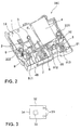
- Fig. 2 shows a locking device for locking the interior of a device according to an embodiment of the present invention.
- Fig. 3 shows a holding element, which is arranged in the region of a closing element of the device according to an embodiment of the present invention.
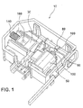
- 4 shows a perspective view of a closing device according to an embodiment of the present invention.
- Fig. 5 shows as a device built-in refrigerator for a camping vehicle, which uses two locking devices according to the invention in two different doors as closing elements.
- Fig. 1 shows a closure for a household appliance, as in DE 102005017870 A1 is set out.
- the closure 10 shown there has a holding element with a recess 160 into which a latch engages, the holding element being designated 30.
- an electromagnet 50 with actuating plunger 90 can be seen, wherein the plunger is returned via a compression spring 150.
- a rocker switch 80 is mounted, in which engages the plunger 90 for rotating the shaft.
- the holding element 30 is biased by a spring 140 and that the closing mechanism is elaborately constructed.
- Fig. 2 shows an embodiment of a closing device 200 according to the invention.
- fastening elements 221 and 222 are arranged, by means of which the locking device on the interior of a device can be attached to the housing.
- the closing device has an interior lighting in the form of a light-emitting diode 1.
- a mechanically simple constructed crankshaft 5 can be seen, on which a crank 51 is arranged.
- the crankshaft is rotatably mounted mechanically stable at bearings 511, 512 and 513 in the housing 46.
- a tension spring can be arranged for mechanically biasing the crank in order to mechanically stabilize the crank in two locking positions.
- a closing hook or a latch 7 can be clearly seen, which engages in a holding device shown in Fig. 3 in the region of the closing element when the closing device is actuated.
- a first detector 9 can be seen, which emits a bolt signal in conjunction with a magnet 8, with which the orientation of the bolt can be detected.
- a second detector 2 can be seen, which is actuated via a magnet 1, which performs a closing detection via a slide 6, when the holding element when engaging in the closing device moves the slider over the detector 2 away and thus the magnet, for example, operates a reed switch ,
- a control circuit board 10 is shown schematically in the region of the housing 46, which contains microcircuits, which serve to control the locking device and to evaluate the signals supplied by the detectors.
- Fig. 2 the mechanically simple construction of the locking device according to the invention, because as shown here in this embodiment, the bolt 7 is actuated directly via the shaft 5.
- a slide 6 is arranged here, which actuates the second detector, so that several functions are compactly combined in one housing and, for example, a lighting circuit is also contained in the housing of the closing device 200.
- the controller on the control board 10 or via a contact, not shown here as an interface to the outside, externally defined states of the detectors 2 and 9 can be detected.
- the latch 7 is opened. That is, when the reed switch 9 outputs a signal, the latch is opened. If the reed switch 9 does not emit a signal, then the bolt is closed, that is, it is in the raised position, whereby the magnet 8 is lowered. More clearly, this state can be seen in FIG. 4.
- this switching signal can be used to activate the light emitting diode. It can also be seen from the illustration that a holding element, which is introduced into the housing in the region of the bolt 7, shifts the slider 6 to the rear and thus removes the magnet 3 from the detector 2. In this case, a spring 49 shown in Fig. 4 is biased.
- Fig. 3 shows an example of a holding element in the region of a closing element according to the invention.
- mounting holes 33 are provided with which the retaining element 32 can be attached to a door via screws or rivets or other fastening means. It is characteristic here that the holding element 32 has an opening 35 into which the latch 7 shown in FIG. 2 engages when actuated.
- the holding device is designed as a plate or thin sheet that enter without appreciable mechanical contact in the locking device and exit from it can.
- the slide 6 shown in FIG. 2 for triggering a closing signal.
- FIG. 4 advantageously shows a further illustration of an embodiment of the closing device according to the invention.
- the open housing 46 is shown and clearly springs 44, 47 and 49 can be seen.
- the spring 44 stabilizes the crankshaft 5 shown in Fig. 2 in two orientations, which can be brought about by the magnet 4 in a known manner via a switching rocker.
- the latch 7 is in the closed position, wherein the magnet 8 is tilted down so that it does not actuate the detector 9.
- a circuit 41 and communication contacts 43 via which the circuit 41 can be communicated externally and via which current can be supplied to the circuit.
- the microprocessor-controlled circuit can perform all functions for controlling the locking device according to the invention and for evaluating the signals supplied by the detectors.
- the closing device according to the invention is operated with 12 V DC and it is particularly advantageous, it is possible to initiate the closing process via a signal that is emitted when the ignition is turned on, that is usually when D +.
- the magnet in the locking device designed as a monostable magnet.
- the closing device according to the invention can be used in absorber cooling devices for boats, motor caravans and caravans, hotels and similar places.
- the circuit 41 can also be used to evaluate the filling state of a minibar, wherein status signals are supplied via the external contact 43, the fill states of individual locations of the minibar characterize. If appropriate, corresponding programs are to be loaded into the memory of the controller and additional evaluation routines to be provided.
- the locking device according to the invention has an emergency release via a button so that even with adjacent D +, that is, the ignition of the vehicle is turned on and the engine is running, access to the refrigerator is possible.
- the circuit according to the invention is designed so that it has the lowest possible quiescent current consumption, which is ensured for example via a sleep mode in which the circuit consumes less than 10 uA.
- FIG. 5 shows a built-in refrigerator for a recreational vehicle 500 having a freezer compartment 510 and a standard refrigerated compartment 520.
- two closing devices according to the invention are installed and labeled 200. If the closing device is not actuated, then the closing element, here the refrigerator door, by a magnetic seal 550, as known from household appliances, kept closed.
- this locking device has a plurality of detectors for detecting states of the bolt, as well as the closing element and an integrated lighting unit, and a controller with a communication bus that can be queried from the outside.
- the mechanical wear is minimized by an optimization of the locking device according to the invention to possible contactless working out, and accordingly, the simple structure also ensures a reliable long-term operation.
Landscapes
- Engineering & Computer Science (AREA)
- Physics & Mathematics (AREA)
- Chemical & Material Sciences (AREA)
- Combustion & Propulsion (AREA)
- Mechanical Engineering (AREA)
- Thermal Sciences (AREA)
- General Engineering & Computer Science (AREA)
- Electromagnetism (AREA)
- Lock And Its Accessories (AREA)
- Devices That Are Associated With Refrigeration Equipment (AREA)
- Passenger Equipment (AREA)
Abstract
Description
- Die Erfindung betrifft eine Schließvorrichtung zum Verriegeln des Innenraums eines Gerätes, wobei der Innenraum üblicherweise mit einem Schließelement, wie einer Türe, einem Schieber, einer Klappe, einem Rollladen oder ähnlichem verschlossen wird.
- Solche Schließvorrichtungen werden insbesondere bei Hausgeräten oder Haushaltsgeräten benötigt, bei denen während des Betriebs kein Zugang durch Bediener zum Innenraum erlangt werden soll, wie beispielsweise Waschmaschinen, Mikrowellen, Spülmaschinen oder ähnlichen Geräten. Entweder bestehen zum Beispiel beim Öffnen des Gerätes während des Betriebs Gefahren für den Bediener, oder es können Betriebsmittel des Gerätes in die Umgebung austreten.
- Ein spezieller Bedarf an Schließvorrichtungen besteht auch, wenn Geräte in dynamischen Umgebungen eingesetzt werden, wie beispielsweise auf Schiffen, Flugzeugen, Zügen, oder Freizeitfahrzeugen. Unter Freizeitfahrzeugen sind in diesem Zusammenhang sowohl Caravans wie auch selbstfahrende Motorcaravans und Wasserfahrzeuge (wie beispielsweise Y-achten) zu verstehen.
- Insbesondere beim Einsatz im Straßenverkehr müssen spezielle Erfordernisse der Straßenverkehrsordnung beachtet werden, die bestimmte Sicherheitsvorschriften in Bezug auf auftretende Beschleunigungs- und Verzögerungskräfte und Belastungen des Verschlussmechanismus der Schließvorrichtung beinhalten, so dass beim Beschleunigen oder Verzögern eines Freizeitfahrzeugs beispielsweise der Inhalt eines Kühlschranks zuverlässig durch das Schließelement und die Schließvorrichtung zurückgehalten werden kann. In diesem Zusammenhang haben sich bisher im Stand der Technik mechanische Verriegelungen herauskristallisiert, bei denen im Bereich einer Türe als Schließelement ein Schließhaken angebracht ist, der mechanisch betätigbar ist, welcher in eine Schlossfalle eingreift, die im Bereich des Innenraums des Gerätes an der Schließvorrichtung angebracht ist.
- Derartige Schließvorrichtungen haben den Nachteil, dass sie mechanisch betätigt werden müssen und dass entsprechende Auslösemechanismen vorgesehen sein müssen, die den Schließhaken betätigen. Weiterhin müssen die Auslösemechanismen für die Schließvorrichtungen konstruktiv so ausgelegt werden, dass sie unterschiedlichen Anschlagseiten von Türen an Haushaltsgeräten Rechnung tragen. Aus
DE 102005017870 A1 ist beispielsweise eine Schließvorrichtung bekannt, bei der im Bereich eines Schlosses für ein Hausgerät eine Haltevorrichtung angeordnet ist, die mittels eines Elektromagneten und über eine Kulissenschaltung arretiert werden kann. Einem Schließhaken, der an einer beispielsweise Türe vorgesehen ist, ist es dann nicht mehr möglich, aus dem Halteelement auszutreten, weil dieses blockiert ist. - Derartige mechanische Verschlusselemente, die elektromagnetisch verriegelt werden, haben jedoch den Nachteil, dass sie bei einer fortwährenden Benutzung eines Haushaltsgerätes, wie beispielsweise eines Kühlschranks, den Komforteindruck, den der Bediener vom Gerät hat, nachteilig beeinflussen, weil er einen mechanischen Widerstand beim Öffnen und Schließen überwinden muss. Bei Haushaltsgeräten ist es der Bediener gewöhnt, dass er lediglich den Widerstand einer Magnetdichtung überwinden muss und dann eine Kühlschranktüre leicht öffnen kann. Weiterhin ist die im Stand der Technik dargestellte Mechanik kompliziert und folglich bei häufiger Beanspruchung auch eher schadensanfällig.
- Ausgehend von diesem Stand der Technik setzt es sich die Erfindung zum Ziel, eine komfortablere Schließvorrichtung für ein Gerät mit Innenraum und ein Gerät mit Schließvorrichtung anzugeben.
- Diese Aufgabe wird gemäß der Erfindung für eine Schließvorrichtung mit den Merkmalen des Patentanspruches 1 gelöst und für ein Gerät mit den Merkmalen des Patentanspruches 13.
- Vorteilhafte Weiterbildungen der Erfindung sind in den abhängigen Ansprüchen 2 bis 12 angegeben.
- Besonders vorteilhaft besitzt eine Schließvorrichtung gemäß der Erfindung einen Riegel, der in ein Halteelement eingreift, das an einem Schließelement angeordnet ist. Das Halteelement weist keine vorspringenden Teile auf, und deswegen ist die Schließvorrichtung beim häufig Öffnen und Schließen keiner mechanischen Beanspruchung ausgesetzt. Weiterhin besitzt die erfindungsgemäße Schließvorrichtung vorteilhaft einen Elektromagneten, der den Riegel betätigt. Diese Art der Betätigung ist gegenüber dem Stand der Technik mechanisch einfacher und deswegen zuverlässiger, weil sie auf überzählige mechanische Elemente verzichtet.
- Vorteilhaft weist eine Weiterbildung der erfindungsgemäßen Schließvorrichtung einen Detektor auf, mit welchem die Orientierung des Riegels detektiert wird, welche ein Riegelsignal schaltet. Auf diese Weise kann über eine Fernauswertung festgestellt werden, ob die Schließvorrichtung verriegelt ist, oder ob sie geöffnet ist.
- Vorteilhaft ist bei einer Weiterbildung der erfindungsgemäßen Schließvorrichtung der Riegel auf einer Kurbelwelle angeordnet, wobei die Kurbel mechanisch vorbelastet ist, sodass vorteilhaft die zwei Orientierungen des Riegels mechanisch stabilisiert werden.
- Besonders vorteilhaft wird der Übergang zwischen den zwei Orientierungen des Riegels über eine Schaltwippe bewirkt, wobei die Schaltwippe mittelbar oder unmittelbar durch einen Elektromagneten betätigt wird. Eine derartige Vorrichtung ist mechanisch sehr zuverlässig. Dies ist beispielsweise auch von der Kugelschreiber Betätigung her bekannt.
- Besonders vorteilhaft ist bei einer Weiterbildung der erfindungsgemäßen Schließvorrichtung im Bereich der Schließvorrichtung am Gerät ein zweiter Detektor zur Detektion der Gegenwart des Halteelementes angeordnet, der ein Schließsignal schaltet. Auf diese Weise kann zuverlässig vorteilhaft festgestellt werden, ob das Schließelement, das heißt die Tür, verschlossen ist oder geöffnet ist. Diese Information kann zur Ferndiagnose verwendet werden, für eine Sicherheitsabschaltung oder einen Alarm, zum Steuern einer Innenraumbeleuchtung, und um bestimmte Schließzustände auch in Verbindung mit dem Riegelsignal definiert zu schalten.
- Besonders vorteilhaft ist bei einer Weiterbildung der erfindungsgemäßen Schließvorrichtung im Bereich der Schließvorrichtung eine Beleuchtungseinrichtung angeordnet, die über das Schließsignal geschaltet wird. Auf diese Weise kann auf eine zusätzliche Verkabelung für die Beleuchtung verzichtet werden, und das Schließsignal kann zusätzlich zum Schalten der Beleuchtungseinrichtung verwendet werden.
- Besonders vorteilhaft sieht es eine Weiterbildung der erfindungsgemäßen Schließvorrichtung vor, dass der Elektromagnet von außerhalb auslösbar ist, sodass beispielsweise ferngesteuert eine Verriegelung oder eine Entriegelung der Schließvorrichtung ausgelöst werden kann, zum Beispiel von einer Fahrerkabine eines Wohnmobils, oder auch die Schließvorrichtung entriegelt werden kann, indem ein Schalter in einem Bereich vorgesehen wird, der zum Beispiel auch für Kinder zugänglich ist.
- Besonders vorteilhaft sieht es eine Weiterbildung der erfindungsgemäßen Schließvorrichtung vor, dass der Elektromagnet in Abhängigkeit des Riegelsignals und des Schließsignals angesteuert wird, so kann vorteilhaft sichergestellt werden, dass der Riegel lediglich ausgelöst wird, wenn das Schließelement, das heißt die Tür, geschlossen wird, oder es kann bei Verriegelung des Gerätes und geöffneter Tür sichergestellt werden, dass ein Schließvorgang problemlos durchgeführt werden kann, auch wenn eine mechanische starre Verriegelung vorgesehen ist.
- Besonders vorteilhaft sieht es eine Weiterbildung der erfindungsgemäßen Schließvorrichtung vor, dass der Elektromagnet über ein Zündungs-Einsignal eines Kfz angesteuert wird, so kann vorteilhaft beim Starten zum Beispiel eines Wohnmobils sichergestellt werden, dass der Kühlschrank beispielsweise automatisch verriegelt wird.
- Besonders vorteilhaft sieht es eine Weiterbildung der erfindungsgemäßen Schließvorrichtung vor, dass alle zum Schließvorgang benötigten Komponenten in einem kompakten Gehäuse zusammengefasst sind, das ebenso eine Steuerungseinrichtung enthält. Auf diese Weise ist die Schließvorrichtung kompakt herstellbar und als ein Gerät vertreibbar und beliebig in einer optimalen Lage am Gerät zu montieren.
- Besonders vorteilhaft sind bei einer Weiterbildung der erfindungsgemäßen Schließvorrichtung die Detektoren als Reedschalter ausgeführt, die berührungslos über Magneten betätigt werden, weil auf diese Weise keinerlei mechanische Beanspruchung durch die Detektoren verursacht wird und eine Langzeitstabilität gewährleistet wird, weil die Detektoren keinem Verschleiß unterliegen. Ebenso sind die Ausgangssignale von Reedschaltern zuverlässig durch eine elektronische Steuerschaltung auswertbar.
- Besonders vorteilhaft sieht es eine Weiterbildung der erfindungsgemäßen Schließvorrichtung vor, dass eine Kommunikationsschnittstelle an der Schließvorrichtung angeordnet wird, weil auf diese Weise optimal alle detektierten Signale und Zustandssignale einer Steuerung nach außen abgeführt werden können, bzw. Steuerungssignale von außen der Steuerung zugeführt werden können.
- Ferner ist vorteilhaft vorgesehen, dass das Schließelement des Gerätes auch im verriegelten Zustand des Riegels verschließbar ist und nach dem Schließen des Schließelements dieses auch verriegelt wird.
- Besonders vorteilhaft wird die erfindungsgemäße Schließvorrichtung in einem Gerät, insbesondere einem Kühlschrank in einem Freizeitfahrzeug, eingesetzt, weil dort zuverlässig alle Vorteile der Erfindung zur Geltung kommen.
- Im Folgenden wird die Erfindung anhand von Ausführungsbeispielen und Figuren weiter erläutert.
- Fig. 1 zeigt einen Verschluss für ein Hausgerät nach dem Stand der Technik.
Fig. 2 zeigt eine Schließvorrichtung zum Verriegeln des Innenraums eines Gerätes gemäß einer Ausführungsform der vorliegenden Erfindung.
Fig. 3 zeigt ein Halteelement, das im Bereich eines Schließelementes des Gerätes angeordnet ist nach einem Ausführungsbeispiel der vorliegenden Erfindung.
Fig. 4 zeigt eine perspektivische Ansicht einer Schließvorrichtung nach einer Ausführungsform der vorliegenden Erfindung.
Fig. 5 zeigt als Gerät einen Einbaukühlschrank für ein Campingmobil, der zwei erfindungsgemäße Schließvorrichtungen bei zwei verschiedenen Türen als Schließelemente einsetzt. - Fig. 1 zeigt einen Verschluss für ein Hausgerät, wie er in
DE 102005017870 A1 dargelegt wird. Der dort dargestellte Verschluss 10 weist ein Halteelement mit Ausnehmung 160 auf, in welche ein Riegel eingreift, wobei das Halteelement mit 30 bezeichnet ist. Weiterhin sind in der Darstellung ein Elektromagnet 50 mit Betätigungsstößel 90 zu erkennen, wobei der Stößel über eine Druckfeder 150 zurückgeführt wird. An einer Betätigungswelle mit Kulisse 100 ist eine Schaltwippe 80 angebracht, in welche der Stößel 90 zum Verdrehen der Welle eingreift. Deutlich ist zu erkennen, dass das Halteelement 30 über eine Feder 140 vorgespannt wird und dass die Schließmechanik aufwändig konstruiert ist. - Beim Stand der Technik wird über eine Betätigung der Welle über die Kulisse 10 eine Bewegung des Halteelementes 30 gegen die Feder 140 herbeigeführt, sodass sich ein Schließhaken, der in das Halteelement eingreift, nicht mehr aus diesem entfernen kann.
- Fig. 2 zeigt ein Ausführungsbeispiel einer erfindungsgemäßen Schließvorrichtung 200. An der Schließvorrichtung sind Befestigungselemente 221 und 222 angeordnet, mittels derer die Schließvorrichtung am Innenraum eines Gerätes am Gehäuse befestigt werden kann. Weiterhin weist die Schließvorrichtung eine Innenraumbeleuchtung in Form einer Leuchtdiode 1 auf. Ebenfalls ist eine mechanisch einfach konstruierte Kurbelwelle 5 zu erkennen, an der eine Kurbel 51 angeordnet ist. Die Kurbelwelle ist drehbar an Lagerstellen 511, 512 und 513 im Gehäuse 46 mechanisch stabil gelagert. Zwischen der Kurbel 51 und einem Befestigungspunkt 15 kann zur mechanischen Vorspannung der Kurbel eine Spannfeder angeordnet werden, um die Kurbel mechanisch in zwei Riegelpositionen zu stabilisieren. Weiterhin ist deutlich ein Schließhaken bzw. ein Riegel 7 zu erkennen, der in eine in Fig. 3 dargestellte Haltevorrichtung im Bereich des Schließelementes eingreift, wenn die Schließvorrichtung betätigt wird. Ebenso ist ein erster Detektor 9 zu erkennen, der in Verbindung mit einem Magneten 8 ein Riegelsignal abgibt, mit welchem die Orientierung des Riegels erkannt werden kann.
- Weiterhin ist ein zweiter Detektor 2 zu erkennen, der über einen Magneten 1 betätigt wird, welcher über einen Schieber 6 eine Schließdetektion durchführt, wenn das Halteelement beim Eingreifen in die Schließvorrichtung den Schieber über den Detektor 2 hinweg verschiebt und damit der Magnet beispielsweise einen Reedschalter betätigt.
- Weiterhin ist schematisch im Bereich des Gehäuses 46 eine Steuerungsplatine 10 dargestellt, welche Mikroschaltkreise enthält, die zur Steuerung der Schließvorrichtung und zur Auswertung der von den Detektoren gelieferten Signale dienen. Deutlich ist in Fig. 2 der mechanisch einfache Aufbau der erfindungsgemäßen Schließvorrichtung zu erkennen, weil wie hier dargestellt in diesem Ausführungsbeispiel der Riegel 7 direkt über die Welle 5 betätigt wird.
- Besonders vorteilhaft ist ebenso deutlich aus Fig. 2 zu erkennen, dass hier ein Schieber 6 angeordnet ist, der den zweiten Detektor betätigt, sodass mehrere Funktionen in einem Gehäuse kompakt zusammengeführt werden und beispielsweise ebenso eine Beleuchtungsschaltung im Gehäuse der Schließvorrichtung 200 enthalten ist.
- In diesem Zusammenhang ist zu bemerken, dass von der Steuerung auf der Steuerungsplatine 10 oder über einen hier nicht dargestellten Kontakt als einer Schnittstelle nach außen, von außen definierte Zustände der Detektoren 2 und 9 erkannt werden können. Wenn sich der Magnet 8 gegenüber dem Detektor 9 befindet, so ist der Riegel 7 geöffnet. Das heißt, wenn der Reedschalter 9 ein Signal abgibt, ist der Riegel geöffnet. Gibt der Reedschalter 9 kein Signal ab, so ist der Riegel verschlossen, das heißt, er befindet sich in der gehobenen Position, wodurch der Magnet 8 abgesenkt wird. Deutlicher ist dieser Zustand in Fig. 4 zu erkennen. Im Gegensatz dazu gibt der Detektor 2, der über einen Magneten 3, wenn er als Reedschalter ausgeführt ist, betätigt wird, ein Signal ab, wenn das Schließelement geöffnet ist, das heißt der Schieber 6 nicht betätigt wird. Dieser Zustand kann deutlich auch in Fig. 4 erkannt werden, wo sich der Magnet direkt über dem Reedschalter befindet.
- Vorteilhaft kann dieses Schaltsignal verwendet werden, um die Leuchtdiode zu aktivieren. Aus der Darstellung kann auch erkannt werden, dass ein Halteelement, das in das Gehäuse im Bereich des Riegels 7 eingeführt wird, den Schieber 6 nach hinten verschiebt und so den Magneten 3 vom Detektor 2 entfernt. Dabei wird eine in Fig. 4 dargestellte Feder 49 vorgespannt.
- Selbstverständlich sind beliebige andere Varianten von Detektoren und Schaltzuständen im Zusammenhang mit der Erfindung realisierbar.
- Fig. 3 zeigt ein Beispiel eines Halteelementes im Bereich eines Schließelementes gemäß der Erfindung. Zum Beispiel sind Befestigungsbohrungen 33 vorgesehen, mit denen das Halteelement 32 an einer Tür über Schrauben oder Nieten oder sonstige Befestigungsmittel befestigt werden kann. Charakteristisch ist hier, dass das Halteelement 32 eine Öffnung 35 aufweist, in welche der in Fig. 2 dargestellte Riegel 7 bei Betätigung eingreift.
- Vorteilhaft wird so beispielsweise einem Benutzer das Gefühl vermittelt, dass er einen normalen Haushaltskühlschrank bedient, wenn die erfindungsgemäße Schließvorrichtung nicht betätigt ist, weil die Haltevorrichtung als Platte bzw. dünnes Blech ausgeführt ist, die ohne nennenswerten mechanischen Kontakt in die Schließvorrichtung eintreten und aus ihr austreten kann. Mit einer Stirnseite 34 betätigt sie dabei beispielsweise beim Eintreten in die Schließvorrichtung den in Fig. 2 dargestellten Schieber 6 zur Auslösung eines Schließsignals.
- Fig. 4 zeigt vorteilhaft eine weitere Darstellung einer Ausführungsform der erfindungsgemäßen Schließvorrichtung. Speziell ist in Fig. 4 das geöffnete Gehäuse 46 dargestellt und deutlich sind Federn 44, 47 und 49 zu erkennen. Die Feder 44 stabilisiert dabei die in Fig. 2 dargestellte Kurbelwelle 5 in zwei Orientierungen, welche durch den Magneten 4 auf bekannte Weise über eine Schaltwippe herbeigeführt werden können. Deutlich ist hier auch zu erkennen, dass der Riegel 7 sich in Schließposition befindet, wobei der Magnet 8 nach unten abgekippt ist, sodass er den Detektor 9 nicht betätigt. Auch ist deutlich eine Schaltung 41 zu erkennen und Kommunikationskontakte 43, über die von außen mit der Schaltung 41 kommuniziert werden kann und über welche der Schaltung Strom zugeführt werden kann. In diesem Beispiel kann gemäß der Erfindung die Mikroprozessor gesteuerte Schaltung alle Funktionen zur Steuerung der erfindungsgemäßen Schließvorrichtung und zur Auswertung der von den Detektoren gelieferten Signale ausführen.
- Weiterhin ist es möglich, dass Diagnosesignale nach außen gesendet werden, um auf einfache Weise das Funktionieren der Schaltung überprüfen zu können. Besonders vorteilhaft wird die erfindungsgemäße Schließvorrichtung mit 12 V Gleichspannung betrieben und besonders vorteilhaft ist es möglich, den Schließvorgang über ein Signal einzuleiten, das bei eingeschalteter Zündung abgegeben wird, das heißt üblicherweise bei angelegtem D+. Besonders vorteilhaft ist der Magnet in der Schließvorrichtung als monostabiler Magnet ausgeführt. Besonders vorteilhaft kann die erfindungsgemäße Schließvorrichtung in Absorberkühlgeräten für Boote, Motorcaravans und Caravans, Hotels und ähnlichen Orten verwendet werden.
- Speziell beim Einsatz in Hotels kann die Schaltung 41 ebenso verwendet werden, um den Füllzustand einer Minibar auszuwerten, wobei Zustandssignale über den Außenkontakt 43 zugeführt werden, die Füllzustände von einzelnen Orten der Minibar kennzeichnen. Gegebenenfalls sind entsprechende Programme in den Speicher der Steuerung zu laden und entsprechende Auswerteroutinen zusätzlich bereitzustellen.
- Weiterhin vorteilhaft besitzt die erfindungsgemäße Schließvorrichtung eine Notentriegelung über einen Taster, sodass selbst bei anliegendem D+, das heißt die Zündung des Fahrzeugs ist eingeschaltet und der Motor läuft, Zugang zum Kühlschrank möglich ist.
- Weiterhin vorteilhaft ist die erfindungsgemäße Schaltung so ausgelegt, dass sie einen möglichst geringen Ruhestromverbrauch aufweist, der beispielsweise über einen Schlafmodus sichergestellt wird, in dem die Schaltung weniger als 10 µA verbraucht.
- Fig. 5 zeigt als Beispiel einen Einbaukühlschrank für ein Freizeitmobil 500, der ein Frosterfach 510 und ein normales Kühlfach 520 aufweist. Im Bereich des Kühlschrankes 500 sind zwei erfindungsgemäße Schließvorrichtungen eingebaut und mit 200 bezeichnet. Wenn die Schließvorrichtung nicht betätigt ist, dann wird das Schließelement, hier die Kühlschranktüre, durch eine Magnetdichtung 550, wie von Haushaltsgeräten bekannt, geschlossen gehalten.
- Über die obige Beschreibung wurde eine höchst einfache und kompakte Schließvorrichtung für Geräte mit Innenraum beschrieben, die als kompakte Einheit vermarktbar ist. Besonders vorteilhaft weist diese Schließvorrichtung mehrere Detektoren auf zur Detektion von Zuständen des Riegels, sowie des Schließelementes und eine integrierte Beleuchtungseinheit, sowie eine Steuerung mit einem Kommunikationsbus, der von außen abgefragt werden kann auf. Der mechanische Verschleiß ist durch eine Optimierung der erfindungsgemäßen Schließvorrichtung auf möglichst berührungsloses Arbeiten hin minimiert, und demgemäß gewährleistet der einfache Aufbau auch einen zuverlässigen Langzeitbetrieb.
Claims (14)
- Schließvorrichtung (200) zum Verriegeln des Innenraums eines Gerätes (500) mit folgenden Merkmalen:am Gerät (500) ist ein Riegel (7) angeordnet,an einem Schließelement (530), das den Innenraum des Gerätes (500) verschließt, ist ein Halteelement (32) angeordnet, das mit dem Riegel (7) beim Verriegeln zusammenwirkt,der Riegel (7) weist zwei vorbelastete stabile Orientierungen auf, wobei in einer ersten Orientierung der Riegel (7) das Halteelement (32) freigibt, und in der zweiten Orientierung der Riegel (7) das Halteelement (32) verriegelt und die mechanische Anordnung zwischen Riegel (7) und Halteelement (32) so ausgestaltet ist, dass beim Schließen des Schließelementes (530), wenn sich der Riegel (7) in der ersten Orientierung befindet, ein Zwischenraum zwischen dem Riegel (7) und dem Halteelement (32) verbleibt,der Riegel wird über einen Elektromagneten betätigt.
- Vorrichtung nach Anspruch 1, bei der der Riegel (7) in Wirkverbindung mit einem ersten Detektor (9, 8) zur Detektion der Orientierung steht, der ein Riegelsignal schaltet.
- Vorrichtung nach einem der Ansprüche 1 oder 2, bei der der Riegel (7) auf einer Kurbelwelle (5) angeordnet ist, wobei eine Kurbel mechanisch vorbelastet ist.
- Vorrichtung nach Anspruch 3, bei der auf der Kurbelwelle (5) eine Schaltwippe (55) angeordnet ist zum Hin- und Herschalten zwischen zwei Orientierungen und die Schaltwippe (55) beim Schalten mit dem Elektromagneten (4) in Wirkverbindung steht.
- Vorrichtung nach einem der vorhergehenden Ansprüche, bei der im Bereich der Schließvorrichtung (200) am Gerät (500) ein zweiter Detektor (2, 3) zur Detektion der Gegenwart des Halteelementes (32) angeordnet ist, der ein Schließsignal schaltet.
- Vorrichtung nach Anspruch 5, bei der an der Schließvorrichtung (200) eine Beleuchtungseinrichtung (1) angeordnet ist, die über das Schließsignal geschaltet wird.
- Vorrichtung nach einem der vorhergehenden Ansprüche, bei der der Elektromagnet (4) von außerhalb der Schließvorrichtung ansteuerbar ist.
- Vorrichtung nach Anspruch 2 in Verbindung mit Anspruch 5 und 7, bei der der Elektromagnet (4) in Abhängigkeit des Riegelsignals und des Schließsignals ansteuerbar ist.
- Vorrichtung nach Anspruch 8, bei der der Elektromagnet (4) über ein Zündungs-Einsignal eines Kfz ansteuerbar ist.
- Vorrichtung nach einem der Ansprüche 1 bis 9, bei der die am Gerät angeordneten Komponenten der Schließvorrichtung (200) in einem Gehäuse (46) zusammengefasst sind und das Gehäuse eine Steuereinrichtung (10, 41) enthält.
- Vorrichtung nach einem der Ansprüche 2 bis 10, bei der die Detektoren (2, 3, 8, 9) als Reedschalter ausgeführt sind.
- Vorrichtung nach Anspruch 10 oder Anspruch 11, bei der eine Kommunikationsschnittstelle (43) angeordnet ist, über die Detektionssignale und Steuerungsfunktionen kommunizierbar sind.
- Vorrichtung nach einem der Ansprüche 1 bis 12, bei der das Schließelement (530) des Gerätes (500) auch im verriegelten Zustand des Riegels (7) verschließbar ist und nach dem Schließen des Schließelements (530) dieses auch verriegelt wird.
- Gerät, insbesondere Kühlschrank, insbesondere in einem Campingfahrzeug mit einer Vorrichtung nach einem der Ansprüche 1 bis 12.
Applications Claiming Priority (1)
| Application Number | Priority Date | Filing Date | Title |
|---|---|---|---|
| DE102006047715A DE102006047715A1 (de) | 2006-10-09 | 2006-10-09 | Schließvorrichtung zum Verriegeln des Innenraums eines Gerätes und Gerät mit Schließvorrichtung |
Publications (3)
| Publication Number | Publication Date |
|---|---|
| EP1939378A2 true EP1939378A2 (de) | 2008-07-02 |
| EP1939378A3 EP1939378A3 (de) | 2008-07-09 |
| EP1939378B1 EP1939378B1 (de) | 2009-07-22 |
Family
ID=39154677
Family Applications (1)
| Application Number | Title | Priority Date | Filing Date |
|---|---|---|---|
| EP20070117335 Not-in-force EP1939378B1 (de) | 2006-10-09 | 2007-09-27 | Schließvorrichtung zum Verriegeln des Innenraums eines Gerätes und Gerät mit Schließvorrichtung |
Country Status (4)
| Country | Link |
|---|---|
| US (1) | US20080083242A1 (de) |
| EP (1) | EP1939378B1 (de) |
| AT (1) | ATE437281T1 (de) |
| DE (2) | DE102006047715A1 (de) |
Cited By (2)
| Publication number | Priority date | Publication date | Assignee | Title |
|---|---|---|---|---|
| USD1002676S1 (en) | 2019-08-30 | 2023-10-24 | Dometic Sweden Ab | Appliance |
| USD1073409S1 (en) | 2023-02-06 | 2025-05-06 | Igloo Products Corp. | Combined cooler and latch |
Families Citing this family (8)
| Publication number | Priority date | Publication date | Assignee | Title |
|---|---|---|---|---|
| DE102010031697A1 (de) * | 2010-06-23 | 2011-12-29 | Liebherr-Hausgeräte Lienz Gmbh | System zur Verriegelung und/oder Entriegelung eines Kühl-und/oder Gefriergerätes |
| AU2012209009B2 (en) * | 2012-07-31 | 2017-09-28 | PMH Manufacturing Pty Limited | A recreational vehicle having at least one internal door or drawer |
| US9631920B2 (en) * | 2013-10-16 | 2017-04-25 | Google Inc. | Sensing system for verifying deadbolt engagement |
| US10550612B2 (en) | 2015-08-20 | 2020-02-04 | Dometic Sweden Ab | Latching handle assembly |
| US10342335B1 (en) | 2016-11-07 | 2019-07-09 | Dometic Sweden Ab | Shelf lock assembly |
| US10982472B1 (en) | 2016-11-07 | 2021-04-20 | Dometic Sweden Ab | Appliance lock assembly |
| USD1026969S1 (en) | 2020-08-31 | 2024-05-14 | Dometic Sweden Ab | Refrigerator |
| EP4368509B1 (de) * | 2022-11-14 | 2026-02-11 | B/E Aerospace, Inc. | Flugzeugbordküchenbehälter |
Family Cites Families (18)
| Publication number | Priority date | Publication date | Assignee | Title |
|---|---|---|---|---|
| US3593816A (en) * | 1968-12-30 | 1971-07-20 | Aisin Seiki | Automotive door lock |
| US4024494A (en) * | 1976-06-17 | 1977-05-17 | Quesnel F Joseph | Refrigerator door lock with alarm |
| DE2833860A1 (de) * | 1978-08-02 | 1980-02-21 | Ellenberger & Poensgen | Bistabile verriegelungsvorrichtung fuer waschmaschinentueren |
| JPS5762380A (en) * | 1980-10-03 | 1982-04-15 | Tokyo Shibaura Electric Co | Quick cooler for refrigerator |
| DE4034853C2 (de) * | 1990-11-02 | 1998-08-06 | Ltd Locking Technologies And D | Magnetverschluß |
| DE19501420C1 (de) * | 1995-01-19 | 1995-12-21 | Dorma Gmbh & Co Kg | Verriegelung |
| US5520424A (en) * | 1995-01-30 | 1996-05-28 | U.S. Controls Copr. | Tamper-proof door switch and latch device |
| DE29708796U1 (de) * | 1997-05-07 | 1997-07-17 | Ikon AG Präzisionstechnik, 14167 Berlin | Bistabile Magnetverriegelung |
| US6053546A (en) * | 1998-06-03 | 2000-04-25 | Harrow Products, Inc. | Trigger system for electromagnetic lock |
| US6363755B1 (en) * | 1999-12-07 | 2002-04-02 | Ark-Les Corporation | Timed release washing machine lid lock |
| JP2001204991A (ja) * | 1999-12-29 | 2001-07-31 | Lg Electronics Inc | ドラム洗濯機のドアロックスイッチアセンブリ |
| DE10038376C2 (de) * | 2000-08-07 | 2003-04-30 | Zangenstein Elektro | Türverriegelung für die Tür eines elektrischen Haushaltsgerätes |
| DE10143123A1 (de) * | 2001-08-29 | 2003-03-20 | Schulte Schlagbaum Ag | Schloss, insbesondere Schrankschloss |
| ATE449227T1 (de) * | 2002-02-27 | 2009-12-15 | Emz Hanauer Gmbh & Co Kgaa | Einheit mit memory-metall-aktuator für türverriegelungen von haushaltsgeräten |
| EP1740752B1 (de) * | 2004-04-27 | 2013-03-27 | Marquardt GmbH | Verschluss für ein hausgerät |
| DE102005017870A1 (de) * | 2004-04-27 | 2005-11-24 | Marquardt Gmbh | Verschluß für ein Hausgerät |
| US7617703B2 (en) * | 2004-11-05 | 2009-11-17 | Illinois Tool Works, Inc. | Washing machine lid lock with memory wire actuator |
| US7446644B2 (en) * | 2005-01-14 | 2008-11-04 | Secureall Corporation | Universal hands free key and lock system |
-
2006
- 2006-10-09 DE DE102006047715A patent/DE102006047715A1/de not_active Withdrawn
-
2007
- 2007-09-27 AT AT07117335T patent/ATE437281T1/de not_active IP Right Cessation
- 2007-09-27 EP EP20070117335 patent/EP1939378B1/de not_active Not-in-force
- 2007-09-27 DE DE200750001112 patent/DE502007001112D1/de active Active
- 2007-10-08 US US11/868,646 patent/US20080083242A1/en not_active Abandoned
Cited By (2)
| Publication number | Priority date | Publication date | Assignee | Title |
|---|---|---|---|---|
| USD1002676S1 (en) | 2019-08-30 | 2023-10-24 | Dometic Sweden Ab | Appliance |
| USD1073409S1 (en) | 2023-02-06 | 2025-05-06 | Igloo Products Corp. | Combined cooler and latch |
Also Published As
| Publication number | Publication date |
|---|---|
| EP1939378A3 (de) | 2008-07-09 |
| DE502007001112D1 (de) | 2009-09-03 |
| EP1939378B1 (de) | 2009-07-22 |
| DE102006047715A1 (de) | 2008-04-10 |
| ATE437281T1 (de) | 2009-08-15 |
| US20080083242A1 (en) | 2008-04-10 |
Similar Documents
| Publication | Publication Date | Title |
|---|---|---|
| EP1939378B1 (de) | Schließvorrichtung zum Verriegeln des Innenraums eines Gerätes und Gerät mit Schließvorrichtung | |
| DE60222261T2 (de) | Verschlusssteuerungseinrichtung mit einer Verriegelungsvorrichtung | |
| DE602004011161T2 (de) | Kraftfahrzeugschliessanlage | |
| DE102009039637B4 (de) | Verriegelungssystem für eine Tür eines Kraftfahrzeugs | |
| EP2032782B1 (de) | Betätigungsvorrichtung | |
| DE19600524B4 (de) | Schloß, insbesondere für Kraftfahrzeugtüren | |
| EP2528785B1 (de) | Steuervorrichtung für ein fahrzeug mit automatisch öffnender und/oder automatisch schliessender klappe | |
| DE102008035607A1 (de) | Schlosseinheit mit zwei Sperrklinken und Positionserkennungsmitteln | |
| DE202015102842U1 (de) | Automatische Schließvorrichtung für Fahrzeugstaufächer | |
| DE102018122443A1 (de) | Kapazitives Feld mit mechanischem Notfallschalter für ein elektronisches Fahrzeug-Zugangssystem | |
| DE102016210251A1 (de) | Schließzylinder-Freigabemechanismus für Fahrzeugschließverriegelungen, Verriegelungsanordnung damit und Verfahren zum mechanischen Freigeben einer Fahrzeugschließverriegelung | |
| DE102014118737A1 (de) | Türverriegelungsschalter mit verriegelungszustandsanzeige | |
| DE60317871T2 (de) | Motorstart Steuerung für ein Fahrzeug | |
| DE102012101898B4 (de) | Fahrzeugsteuerungsvorrichtung | |
| DE112008002710T5 (de) | Schlossbetätigung und Schloss, welches eine solche Betätigung verwendet | |
| DE102013227115A1 (de) | Fahrzeugtürverriegelungssystem und verfahren | |
| DE102004019919B3 (de) | Vorrichtung zum Starten eines Fahrzeugmotors mittels eines elektronischen Schlüssels und ein dazu zu verwendener Schlüssel | |
| DE102022130960A1 (de) | Verschlussverriegelung mit kraftbetätigtem aktuator, der mehrere angetriebene funktionen bietet | |
| EP1116839A2 (de) | Kraftfahrzeug-Türschloss, Kraftfahrzeug-Türschliesssystem und Verfahren zur Steuerung eines Kraftfahrzeug-Türschlosses | |
| DE102022133020A1 (de) | Arretierungskomponente für eine türbetätigungsanordnung | |
| DE202020105043U1 (de) | Fahrzeugaufbewahrungsbaugruppe mit Restmagnetverriegelungsmechanismus | |
| EP0469333B1 (de) | Kraftfahrzeug mit einer Zentralverriegelungsanlage und einer Diebstahl-Alarmanlage | |
| DE10300572A1 (de) | Türgriff und Schließsystem für eine Fahrzeugtür | |
| DE10151022A1 (de) | Kraftfahrzeug-Türschloß mit voneinander getrennter Schließeinheit und Steuereinheit | |
| EP0591669A1 (de) | Verfahren zur Zentralverriegelung eines Kraftfahrzeuges mit Diebstahlsicherungsfunktion und Einrichtung zur Durchführung des Verfahrens |
Legal Events
| Date | Code | Title | Description |
|---|---|---|---|
| PUAI | Public reference made under article 153(3) epc to a published international application that has entered the european phase |
Free format text: ORIGINAL CODE: 0009012 |
|
| PUAL | Search report despatched |
Free format text: ORIGINAL CODE: 0009013 |
|
| AK | Designated contracting states |
Kind code of ref document: A2 Designated state(s): AT BE BG CH CY CZ DE DK EE ES FI FR GB GR HU IE IS IT LI LT LU LV MC MT NL PL PT RO SE SI SK TR |
|
| AX | Request for extension of the european patent |
Extension state: AL BA HR MK RS |
|
| AK | Designated contracting states |
Kind code of ref document: A3 Designated state(s): AT BE BG CH CY CZ DE DK EE ES FI FR GB GR HU IE IS IT LI LT LU LV MC MT NL PL PT RO SE SI SK TR |
|
| AX | Request for extension of the european patent |
Extension state: AL BA HR MK RS |
|
| 17P | Request for examination filed |
Effective date: 20080728 |
|
| GRAP | Despatch of communication of intention to grant a patent |
Free format text: ORIGINAL CODE: EPIDOSNIGR1 |
|
| AKX | Designation fees paid |
Designated state(s): AT BE BG CH CY CZ DE DK EE ES FI FR GB GR HU IE IS IT LI LT LU LV MC MT NL PL PT RO SE SI SK TR |
|
| GRAC | Information related to communication of intention to grant a patent modified |
Free format text: ORIGINAL CODE: EPIDOSCIGR1 |
|
| GRAS | Grant fee paid |
Free format text: ORIGINAL CODE: EPIDOSNIGR3 |
|
| GRAA | (expected) grant |
Free format text: ORIGINAL CODE: 0009210 |
|
| AK | Designated contracting states |
Kind code of ref document: B1 Designated state(s): AT BE BG CH CY CZ DE DK EE ES FI FR GB GR HU IE IS IT LI LT LU LV MC MT NL PL PT RO SE SI SK TR |
|
| REG | Reference to a national code |
Ref country code: GB Ref legal event code: FG4D Free format text: NOT ENGLISH |
|
| REG | Reference to a national code |
Ref country code: CH Ref legal event code: EP |
|
| REG | Reference to a national code |
Ref country code: IE Ref legal event code: FG4D |
|
| REF | Corresponds to: |
Ref document number: 502007001112 Country of ref document: DE Date of ref document: 20090903 Kind code of ref document: P |
|
| PG25 | Lapsed in a contracting state [announced via postgrant information from national office to epo] |
Ref country code: SE Free format text: LAPSE BECAUSE OF FAILURE TO SUBMIT A TRANSLATION OF THE DESCRIPTION OR TO PAY THE FEE WITHIN THE PRESCRIBED TIME-LIMIT Effective date: 20090722 Ref country code: IS Free format text: LAPSE BECAUSE OF FAILURE TO SUBMIT A TRANSLATION OF THE DESCRIPTION OR TO PAY THE FEE WITHIN THE PRESCRIBED TIME-LIMIT Effective date: 20091122 Ref country code: LT Free format text: LAPSE BECAUSE OF FAILURE TO SUBMIT A TRANSLATION OF THE DESCRIPTION OR TO PAY THE FEE WITHIN THE PRESCRIBED TIME-LIMIT Effective date: 20090722 Ref country code: ES Free format text: LAPSE BECAUSE OF FAILURE TO SUBMIT A TRANSLATION OF THE DESCRIPTION OR TO PAY THE FEE WITHIN THE PRESCRIBED TIME-LIMIT Effective date: 20091102 Ref country code: FI Free format text: LAPSE BECAUSE OF FAILURE TO SUBMIT A TRANSLATION OF THE DESCRIPTION OR TO PAY THE FEE WITHIN THE PRESCRIBED TIME-LIMIT Effective date: 20090722 |
|
| PG25 | Lapsed in a contracting state [announced via postgrant information from national office to epo] |
Ref country code: PL Free format text: LAPSE BECAUSE OF FAILURE TO SUBMIT A TRANSLATION OF THE DESCRIPTION OR TO PAY THE FEE WITHIN THE PRESCRIBED TIME-LIMIT Effective date: 20090722 Ref country code: SI Free format text: LAPSE BECAUSE OF FAILURE TO SUBMIT A TRANSLATION OF THE DESCRIPTION OR TO PAY THE FEE WITHIN THE PRESCRIBED TIME-LIMIT Effective date: 20090722 Ref country code: LV Free format text: LAPSE BECAUSE OF FAILURE TO SUBMIT A TRANSLATION OF THE DESCRIPTION OR TO PAY THE FEE WITHIN THE PRESCRIBED TIME-LIMIT Effective date: 20090722 |
|
| REG | Reference to a national code |
Ref country code: IE Ref legal event code: FD4D |
|
| BERE | Be: lapsed |
Owner name: DOMETIC G.M.B.H. Effective date: 20090930 |
|
| PG25 | Lapsed in a contracting state [announced via postgrant information from national office to epo] |
Ref country code: BG Free format text: LAPSE BECAUSE OF FAILURE TO SUBMIT A TRANSLATION OF THE DESCRIPTION OR TO PAY THE FEE WITHIN THE PRESCRIBED TIME-LIMIT Effective date: 20091022 Ref country code: PT Free format text: LAPSE BECAUSE OF FAILURE TO SUBMIT A TRANSLATION OF THE DESCRIPTION OR TO PAY THE FEE WITHIN THE PRESCRIBED TIME-LIMIT Effective date: 20091122 |
|
| PG25 | Lapsed in a contracting state [announced via postgrant information from national office to epo] |
Ref country code: EE Free format text: LAPSE BECAUSE OF FAILURE TO SUBMIT A TRANSLATION OF THE DESCRIPTION OR TO PAY THE FEE WITHIN THE PRESCRIBED TIME-LIMIT Effective date: 20090722 Ref country code: DK Free format text: LAPSE BECAUSE OF FAILURE TO SUBMIT A TRANSLATION OF THE DESCRIPTION OR TO PAY THE FEE WITHIN THE PRESCRIBED TIME-LIMIT Effective date: 20090722 Ref country code: CZ Free format text: LAPSE BECAUSE OF FAILURE TO SUBMIT A TRANSLATION OF THE DESCRIPTION OR TO PAY THE FEE WITHIN THE PRESCRIBED TIME-LIMIT Effective date: 20090722 Ref country code: IE Free format text: LAPSE BECAUSE OF FAILURE TO SUBMIT A TRANSLATION OF THE DESCRIPTION OR TO PAY THE FEE WITHIN THE PRESCRIBED TIME-LIMIT Effective date: 20090722 Ref country code: RO Free format text: LAPSE BECAUSE OF FAILURE TO SUBMIT A TRANSLATION OF THE DESCRIPTION OR TO PAY THE FEE WITHIN THE PRESCRIBED TIME-LIMIT Effective date: 20090722 Ref country code: MC Free format text: LAPSE BECAUSE OF NON-PAYMENT OF DUE FEES Effective date: 20090930 |
|
| PLBE | No opposition filed within time limit |
Free format text: ORIGINAL CODE: 0009261 |
|
| STAA | Information on the status of an ep patent application or granted ep patent |
Free format text: STATUS: NO OPPOSITION FILED WITHIN TIME LIMIT |
|
| PG25 | Lapsed in a contracting state [announced via postgrant information from national office to epo] |
Ref country code: SK Free format text: LAPSE BECAUSE OF FAILURE TO SUBMIT A TRANSLATION OF THE DESCRIPTION OR TO PAY THE FEE WITHIN THE PRESCRIBED TIME-LIMIT Effective date: 20090722 |
|
| 26N | No opposition filed |
Effective date: 20100423 |
|
| PG25 | Lapsed in a contracting state [announced via postgrant information from national office to epo] |
Ref country code: BE Free format text: LAPSE BECAUSE OF NON-PAYMENT OF DUE FEES Effective date: 20090930 |
|
| PG25 | Lapsed in a contracting state [announced via postgrant information from national office to epo] |
Ref country code: GR Free format text: LAPSE BECAUSE OF FAILURE TO SUBMIT A TRANSLATION OF THE DESCRIPTION OR TO PAY THE FEE WITHIN THE PRESCRIBED TIME-LIMIT Effective date: 20091023 |
|
| PG25 | Lapsed in a contracting state [announced via postgrant information from national office to epo] |
Ref country code: AT Free format text: LAPSE BECAUSE OF NON-PAYMENT OF DUE FEES Effective date: 20090927 |
|
| PGFP | Annual fee paid to national office [announced via postgrant information from national office to epo] |
Ref country code: NL Payment date: 20101123 Year of fee payment: 4 |
|
| PGFP | Annual fee paid to national office [announced via postgrant information from national office to epo] |
Ref country code: DE Payment date: 20101028 Year of fee payment: 4 |
|
| PG25 | Lapsed in a contracting state [announced via postgrant information from national office to epo] |
Ref country code: IT Free format text: LAPSE BECAUSE OF FAILURE TO SUBMIT A TRANSLATION OF THE DESCRIPTION OR TO PAY THE FEE WITHIN THE PRESCRIBED TIME-LIMIT Effective date: 20090722 |
|
| PG25 | Lapsed in a contracting state [announced via postgrant information from national office to epo] |
Ref country code: MT Free format text: LAPSE BECAUSE OF FAILURE TO SUBMIT A TRANSLATION OF THE DESCRIPTION OR TO PAY THE FEE WITHIN THE PRESCRIBED TIME-LIMIT Effective date: 20090722 Ref country code: LU Free format text: LAPSE BECAUSE OF NON-PAYMENT OF DUE FEES Effective date: 20090927 |
|
| REG | Reference to a national code |
Ref country code: FR Ref legal event code: ST Effective date: 20110531 |
|
| PG25 | Lapsed in a contracting state [announced via postgrant information from national office to epo] |
Ref country code: HU Free format text: LAPSE BECAUSE OF FAILURE TO SUBMIT A TRANSLATION OF THE DESCRIPTION OR TO PAY THE FEE WITHIN THE PRESCRIBED TIME-LIMIT Effective date: 20100123 |
|
| PG25 | Lapsed in a contracting state [announced via postgrant information from national office to epo] |
Ref country code: FR Free format text: LAPSE BECAUSE OF NON-PAYMENT OF DUE FEES Effective date: 20100930 |
|
| PG25 | Lapsed in a contracting state [announced via postgrant information from national office to epo] |
Ref country code: TR Free format text: LAPSE BECAUSE OF FAILURE TO SUBMIT A TRANSLATION OF THE DESCRIPTION OR TO PAY THE FEE WITHIN THE PRESCRIBED TIME-LIMIT Effective date: 20090722 |
|
| PG25 | Lapsed in a contracting state [announced via postgrant information from national office to epo] |
Ref country code: CY Free format text: LAPSE BECAUSE OF FAILURE TO SUBMIT A TRANSLATION OF THE DESCRIPTION OR TO PAY THE FEE WITHIN THE PRESCRIBED TIME-LIMIT Effective date: 20090722 |
|
| PGFP | Annual fee paid to national office [announced via postgrant information from national office to epo] |
Ref country code: FR Payment date: 20091005 Year of fee payment: 3 |
|
| REG | Reference to a national code |
Ref country code: NL Ref legal event code: V1 Effective date: 20120401 |
|
| REG | Reference to a national code |
Ref country code: CH Ref legal event code: PL |
|
| GBPC | Gb: european patent ceased through non-payment of renewal fee |
Effective date: 20110927 |
|
| REG | Reference to a national code |
Ref country code: DE Ref legal event code: R119 Ref document number: 502007001112 Country of ref document: DE Effective date: 20120403 |
|
| PG25 | Lapsed in a contracting state [announced via postgrant information from national office to epo] |
Ref country code: DE Free format text: LAPSE BECAUSE OF NON-PAYMENT OF DUE FEES Effective date: 20120403 Ref country code: CH Free format text: LAPSE BECAUSE OF NON-PAYMENT OF DUE FEES Effective date: 20110930 Ref country code: NL Free format text: LAPSE BECAUSE OF NON-PAYMENT OF DUE FEES Effective date: 20120401 Ref country code: LI Free format text: LAPSE BECAUSE OF NON-PAYMENT OF DUE FEES Effective date: 20110930 |
|
| PG25 | Lapsed in a contracting state [announced via postgrant information from national office to epo] |
Ref country code: GB Free format text: LAPSE BECAUSE OF NON-PAYMENT OF DUE FEES Effective date: 20110927 |