EP1939428A2 - Dispositif de prévention de flamme - Google Patents
Dispositif de prévention de flamme Download PDFInfo
- Publication number
- EP1939428A2 EP1939428A2 EP20070254744 EP07254744A EP1939428A2 EP 1939428 A2 EP1939428 A2 EP 1939428A2 EP 20070254744 EP20070254744 EP 20070254744 EP 07254744 A EP07254744 A EP 07254744A EP 1939428 A2 EP1939428 A2 EP 1939428A2
- Authority
- EP
- European Patent Office
- Prior art keywords
- gas turbine
- turbine engine
- component
- flame retardant
- prevention device
- Prior art date
- Legal status (The legal status is an assumption and is not a legal conclusion. Google has not performed a legal analysis and makes no representation as to the accuracy of the status listed.)
- Withdrawn
Links
- 230000002265 prevention Effects 0.000 title claims abstract description 44
- 239000000463 material Substances 0.000 claims description 41
- RNFJDJUURJAICM-UHFFFAOYSA-N 2,2,4,4,6,6-hexaphenoxy-1,3,5-triaza-2$l^{5},4$l^{5},6$l^{5}-triphosphacyclohexa-1,3,5-triene Chemical compound N=1P(OC=2C=CC=CC=2)(OC=2C=CC=CC=2)=NP(OC=2C=CC=CC=2)(OC=2C=CC=CC=2)=NP=1(OC=1C=CC=CC=1)OC1=CC=CC=C1 RNFJDJUURJAICM-UHFFFAOYSA-N 0.000 claims description 35
- 239000003063 flame retardant Substances 0.000 claims description 35
- 239000000919 ceramic Substances 0.000 claims description 10
- 238000000576 coating method Methods 0.000 claims description 10
- 239000000853 adhesive Substances 0.000 claims description 4
- 230000001070 adhesive effect Effects 0.000 claims description 4
- 229920006231 aramid fiber Polymers 0.000 claims description 4
- 239000006260 foam Substances 0.000 claims description 4
- 238000005524 ceramic coating Methods 0.000 claims description 2
- 150000004760 silicates Chemical class 0.000 claims description 2
- PXHVJJICTQNCMI-UHFFFAOYSA-N Nickel Chemical compound [Ni] PXHVJJICTQNCMI-UHFFFAOYSA-N 0.000 description 28
- 239000007789 gas Substances 0.000 description 19
- 229910045601 alloy Inorganic materials 0.000 description 15
- 239000000956 alloy Substances 0.000 description 15
- 229910052759 nickel Inorganic materials 0.000 description 15
- 239000011347 resin Substances 0.000 description 14
- 229920005989 resin Polymers 0.000 description 14
- 238000000034 method Methods 0.000 description 11
- 229910001069 Ti alloy Inorganic materials 0.000 description 8
- 239000011248 coating agent Substances 0.000 description 8
- 238000005507 spraying Methods 0.000 description 6
- 230000035515 penetration Effects 0.000 description 5
- XKRFYHLGVUSROY-UHFFFAOYSA-N Argon Chemical compound [Ar] XKRFYHLGVUSROY-UHFFFAOYSA-N 0.000 description 4
- 238000001035 drying Methods 0.000 description 4
- 210000002310 elbow joint Anatomy 0.000 description 4
- 229910052751 metal Inorganic materials 0.000 description 4
- 239000002184 metal Substances 0.000 description 4
- 239000002904 solvent Substances 0.000 description 4
- 239000002270 dispersing agent Substances 0.000 description 3
- 239000000835 fiber Substances 0.000 description 3
- 239000010936 titanium Substances 0.000 description 3
- 229910052719 titanium Inorganic materials 0.000 description 3
- BPQQTUXANYXVAA-UHFFFAOYSA-N Orthosilicate Chemical compound [O-][Si]([O-])([O-])[O-] BPQQTUXANYXVAA-UHFFFAOYSA-N 0.000 description 2
- MCMNRKCIXSYSNV-UHFFFAOYSA-N Zirconium dioxide Chemical compound O=[Zr]=O MCMNRKCIXSYSNV-UHFFFAOYSA-N 0.000 description 2
- 229910052786 argon Inorganic materials 0.000 description 2
- 229910010293 ceramic material Inorganic materials 0.000 description 2
- 229910052804 chromium Inorganic materials 0.000 description 2
- 239000011651 chromium Substances 0.000 description 2
- 238000002485 combustion reaction Methods 0.000 description 2
- 238000002474 experimental method Methods 0.000 description 2
- -1 for example Substances 0.000 description 2
- 229910052742 iron Inorganic materials 0.000 description 2
- XEEYBQQBJWHFJM-UHFFFAOYSA-N iron Substances [Fe] XEEYBQQBJWHFJM-UHFFFAOYSA-N 0.000 description 2
- 210000001503 joint Anatomy 0.000 description 2
- 229910052750 molybdenum Inorganic materials 0.000 description 2
- 230000003647 oxidation Effects 0.000 description 2
- 238000007254 oxidation reaction Methods 0.000 description 2
- 239000004094 surface-active agent Substances 0.000 description 2
- 229920000271 Kevlar® Polymers 0.000 description 1
- RTAQQCXQSZGOHL-UHFFFAOYSA-N Titanium Chemical compound [Ti] RTAQQCXQSZGOHL-UHFFFAOYSA-N 0.000 description 1
- 238000007605 air drying Methods 0.000 description 1
- PNEYBMLMFCGWSK-UHFFFAOYSA-N aluminium oxide Inorganic materials [O-2].[O-2].[O-2].[Al+3].[Al+3] PNEYBMLMFCGWSK-UHFFFAOYSA-N 0.000 description 1
- 230000000712 assembly Effects 0.000 description 1
- 238000000429 assembly Methods 0.000 description 1
- 230000001680 brushing effect Effects 0.000 description 1
- KZHJGOXRZJKJNY-UHFFFAOYSA-N dioxosilane;oxo(oxoalumanyloxy)alumane Chemical compound O=[Si]=O.O=[Si]=O.O=[Al]O[Al]=O.O=[Al]O[Al]=O.O=[Al]O[Al]=O KZHJGOXRZJKJNY-UHFFFAOYSA-N 0.000 description 1
- 230000000694 effects Effects 0.000 description 1
- 239000012530 fluid Substances 0.000 description 1
- 239000000446 fuel Substances 0.000 description 1
- 238000010438 heat treatment Methods 0.000 description 1
- 238000007749 high velocity oxygen fuel spraying Methods 0.000 description 1
- 238000005470 impregnation Methods 0.000 description 1
- 230000000977 initiatory effect Effects 0.000 description 1
- 239000004761 kevlar Substances 0.000 description 1
- 238000012986 modification Methods 0.000 description 1
- 230000004048 modification Effects 0.000 description 1
- 229910052863 mullite Inorganic materials 0.000 description 1
- 229910052574 oxide ceramic Inorganic materials 0.000 description 1
- 239000011224 oxide ceramic Substances 0.000 description 1
- TWNQGVIAIRXVLR-UHFFFAOYSA-N oxo(oxoalumanyloxy)alumane Chemical compound O=[Al]O[Al]=O TWNQGVIAIRXVLR-UHFFFAOYSA-N 0.000 description 1
- 238000010422 painting Methods 0.000 description 1
- 238000007750 plasma spraying Methods 0.000 description 1
- 239000007787 solid Substances 0.000 description 1
- 239000000126 substance Substances 0.000 description 1
- 239000000725 suspension Substances 0.000 description 1
- 238000007751 thermal spraying Methods 0.000 description 1
Images


Classifications
-
- F—MECHANICAL ENGINEERING; LIGHTING; HEATING; WEAPONS; BLASTING
- F02—COMBUSTION ENGINES; HOT-GAS OR COMBUSTION-PRODUCT ENGINE PLANTS
- F02C—GAS-TURBINE PLANTS; AIR INTAKES FOR JET-PROPULSION PLANTS; CONTROLLING FUEL SUPPLY IN AIR-BREATHING JET-PROPULSION PLANTS
- F02C6/00—Plural gas-turbine plants; Combinations of gas-turbine plants with other apparatus; Adaptations of gas-turbine plants for special use
- F02C6/04—Gas-turbine plants providing heated or pressurised working fluid for other apparatus, e.g. without mechanical power output
- F02C6/06—Gas-turbine plants providing heated or pressurised working fluid for other apparatus, e.g. without mechanical power output providing compressed gas
- F02C6/08—Gas-turbine plants providing heated or pressurised working fluid for other apparatus, e.g. without mechanical power output providing compressed gas the gas being bled from the gas-turbine compressor
-
- F—MECHANICAL ENGINEERING; LIGHTING; HEATING; WEAPONS; BLASTING
- F02—COMBUSTION ENGINES; HOT-GAS OR COMBUSTION-PRODUCT ENGINE PLANTS
- F02C—GAS-TURBINE PLANTS; AIR INTAKES FOR JET-PROPULSION PLANTS; CONTROLLING FUEL SUPPLY IN AIR-BREATHING JET-PROPULSION PLANTS
- F02C7/00—Features, components parts, details or accessories, not provided for in, or of interest apart form groups F02C1/00 - F02C6/00; Air intakes for jet-propulsion plants
- F02C7/24—Heat or noise insulation
- F02C7/25—Fire protection or prevention
-
- Y—GENERAL TAGGING OF NEW TECHNOLOGICAL DEVELOPMENTS; GENERAL TAGGING OF CROSS-SECTIONAL TECHNOLOGIES SPANNING OVER SEVERAL SECTIONS OF THE IPC; TECHNICAL SUBJECTS COVERED BY FORMER USPC CROSS-REFERENCE ART COLLECTIONS [XRACs] AND DIGESTS
- Y10—TECHNICAL SUBJECTS COVERED BY FORMER USPC
- Y10T—TECHNICAL SUBJECTS COVERED BY FORMER US CLASSIFICATION
- Y10T442/00—Fabric [woven, knitted, or nonwoven textile or cloth, etc.]
- Y10T442/20—Coated or impregnated woven, knit, or nonwoven fabric which is not [a] associated with another preformed layer or fiber layer or, [b] with respect to woven and knit, characterized, respectively, by a particular or differential weave or knit, wherein the coating or impregnation is neither a foamed material nor a free metal or alloy layer
- Y10T442/2631—Coating or impregnation provides heat or fire protection
Definitions
- the invention relates to flame prevention devices and, more particularly, relates to flame prevention devices for use in aircraft engines.
- a gas turbine engine broadly comprises an engine casing concentrically disposed around the following: a low pressure compressor; a turbine; and a high pressure compressor; and at least one flame prevention device adapted to cover at least a portion of at least one gas turbine engine component.
- a gas turbine engine component broadly comprises a gas turbine engine component having at least a portion of an exterior surface covered by at least one flame prevention device.
- the gas turbine engine includes an annular flowpath 12 extending axially through a compressor section 14, a combustion section 16, and a turbine section 18.
- the compressor section 14 includes a high pressure compressor 22, having a rotor drum 23 comprised of a plurality of rotating disks 23, and a low pressure compressor (not shown).
- the turbine section 18 has a high pressure turbine 26 having a plurality of rotating disks 27 and a low pressure turbine 28 having a plurality of rotating disks 29.
- a low pressure rotor 32 connects the low pressure turbine disks 29 to the low pressure compressor.
- a high pressure rotor 34 connects the high pressure turbine disks 27 to the high pressure compressor rotor drum 23.
- Working fluid is conducted through the flowpath 12 of the compressor section 14 and into the turbine section 26.
- the compressor section 14 may include at least one bleed tube assembly 42 that may be disposed external to the engine casing 11 and connected from the compressor section 14 to the combustion section 16.
- the bleed tube assembly 42 may be connected to the engine housing using joints as known to one of ordinary skill in the art. In a non-limiting example, elbow joints 44, 46 may be used to connect each end of the bleed tube assemblies 42 to the engine casing 11.
- each bleed tube assembly 42 may include a non-limiting, exemplary flame prevention device 50 covering at least a portion of the assembly 42.
- the flame prevention device 50 may be a substantially sleeve-shaped device composed of at least one layer, or multiple layers, of at least one woven flame retardant material.
- the substantially sleeve-shaped device may usefully be flexible and form-fitting to accommodate the shape of the bleed tube assembly 42 (See FIG. 3 ), or other gas turbine engine component, e.g., a joint 44, 46 (See FIG. 4 ).
- the exemplary substantially sleeve-shaped device may be disposed upon bleed tube assembly 42 or joint 44, 46 by wrapping the at least one layer of flame retardant material about the component and securing the material using the fastening means described herein.
- the ends of the substantially sleeve-shaped device may then be affixed to the engine casing by any fastening means such as, but not limited to, sandwiching the material between metal plates; disposing fasteners through the material; using clamps, rings, and the like; applying adhesives to the material; combinations of the aforementioned fastening means, and the like.
- the exemplary flame prevention device 50 may be a substantially sock-shaped device and may only possess one open end. The substantially sock-shaped flame prevention device 50 may be utilized to impart flame prevention to various other turbine engine components.
- the exemplary flame prevention device 50 may be composed of at least one flame retardant material such as ceramics (e.g., alumina, mullite, zirconia, and the like), silicates and aramid fiber based materials.
- Suitable aramid fiber based materials may be a type of Kevlar ® , commercially available from E.I. du Pont de Nemours & Co., Wilmington, Delaware.
- the flame prevention device 50 may be a weave composed of a single material, for example, ceramic based fibers, or a co-weave of a combination of materials, for example, ceramic based fibers and aramid fiber based material woven together.
- the flame retardant material may include a flame retardant coating such as a ceramic material, silicate material, and the like, to further impart flame retardant properties to flame prevention device 50.
- the flame retardant material may be coated prior to being woven, while being woven, or after having been woven but prior to being placed upon the gas turbine engine component, or even after being placed upon the gas turbine engine component.
- each bleed tube assembly 42 may also include yet another exemplary flame prevention device covering at least a portion of the assembly 42.
- the flame prevention device 60 may comprise at least one piece of flame retardant material substantially covered by a coating.
- the flame prevention device 60 may be a shell comprising a first half and a second half or, in the alternative, more than two halves such that the shell is composed of more than two pieces that may be assembled to form the flame prevention device 60 disposed about the gas turbine engine component.
- the pieces of flame retardant material may be composed of a flame retardant ceramic foam known to one of ordinary skill in the art.
- the flame retardant ceramic foam may be preformed to the dimensions and shape of the gas turbine engine component or may be a solid piece of ceramic foam that is later sized to fit the dimensions and shape of the gas turbine engine component.
- the flame retardant materials may be woven to form a weave pattern designed to prevent or at least substantially prevent the complete penetration of molten metal through the exemplary flame prevention devices described herein.
- Each layer of flame retardant material may possess the same weave pattern or a different weave pattern. Any one of a number of weave patterns may be utilized to achieve the desired effect.
- the woven flame retardant material may have a weave pattern such as plain, twill, basket, Leno, Satin, Herringbone, as known to one of ordinary skill in the art.
- the flame prevention device 50 may possess a thickness of about about 5 mils (127 ⁇ m) to about 2000 mils (5.08 x 10 4 ⁇ m); the intended thickness being sufficient to prevent or substantially prevent the complete penetration of molten metal through the exemplary flame prevention devices described herein.
- All of the exemplary flame prevention devices described herein may include a flame retardant coating such as a ceramic material, silicate material, and the like, to further impart flame retardant properties to the flame prevention devices.
- the pieces of flame retardant material may be coated prior to being woven, while being woven, or after having been woven or preformed but prior to being placed upon the gas turbine engine component, or even after being installed upon the gas turbine engine component.
- the flame retardant material may be usefully coated prior to being installed upon the gas turbine engine component.
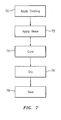
- the pieces of flame retardant material may be coated at step 70 of FIG. 7 using any one of a number of coating techniques known to one of ordinary skill in the art.
- the device may be further treated with a heat- or UV-curable resin at step 72 of FIG. 7 .
- the resin may be applied using a vacuum impregnation technique as known to one of ordinary skill in the art.
- Each piece, or the entire device may be immersed in a solution containing a solvent, at least one UV-curable resin or at least one heat curable resin, at least one dispersant, and in the alternative, or in addition to, at least one surfactant, at a temperature of about 68°F (20°C) to about 150°F (66°C) and initially under a vacuum of about 10 torr (0.19 psi) to about 100 torr (1.9 psi) for about 2 to about 10 minutes at which point the pressure may then be adjusted to atmospheric pressure.
- the solution may also be applied by spraying, brushing, painting, combinations comprising at least one of the foregoing techniques, and the like.
- suitable spraying processes include, but are not limited to, air pressure spraying, airless spraying, thermal spraying processes, air plasma spraying processes, high velocity oxygen fuel spraying processes, combinations comprising at least one of the foregoing spraying processes, and the like.
- Suitable heat- and UV-curable resins are preferably impart properties such as, but not limited to, hardness, elongation, chemical resistance, and the like, to the exemplary flame prevention devices described herein as known to one of ordinary skill in the art.
- Suitable solvent(s), dispersant(s), and surfactant(s) may be selected based upon their compatibility with the curable resin as known to one of ordinary skill in the art.
- the resin coated flame retardant material, or flame prevention device itself may be cured at step 74 of FIG. 7 .
- the resultant resin coated flame retardant material may be treated with ultra-violet light energy to cure the resin.
- the coated article may be treated with ultra-violet light energy for about 10 seconds to about 60 seconds using any one of a number of processes known to one of ordinary skill in the art.
- the resultant coated flame retardant material, or flame prevention device itself may be treated at a temperature of about 300°F (149°C) for about 20 minutes to about 60 minutes in an oven, or similar suitable apparatus, as known to one of ordinary skill in the art.
- the pieces, or flame prevention device itself may be dried at step 76 of FIG. 7 to evaporate or burn off the excess solvent, dispersant and/or resin materials.
- the material or device may be dried using any one of a number of suitable drying processes known to one of ordinary skill in the art. Suitable drying processes include, but are not limited to, air drying, drying under pressure, drying under a heating element, combinations comprising at least one of the foregoing processes, and the like.
- the amount of time necessary to dry the material or device may depend upon several factors and, in particular, the solvent of the suspension.
- the pieces, or the flame prevention device(s) may be sealed together using any number of mechanical fasteners, adhesives, coatings, combinations comprising at least one of the foregoing, and the like, as known to one of ordinary skill in the art.
- the pieces of the flame prevention device 50 may be sealed together using an adhesive or a coating.
- a coating e.g., a ceramic coating
- the pieces may harden and seal together to form the exemplary flame prevention device(s) described herein.
- mechanical fasteners may adequately hold the pieces together, the mechanical fasteners may liberate during engine use.
- the quantity of molten nickel based alloy was poured in a vacuum furnace by emptying the crucible into a ceramic pour cup which directed the molten nickel based alloy onto a AMS 4911 titanium alloy plate measuring 5 in. (127 mm) x 8 in.
- the quantity of molten nickel based alloy was poured in a vacuum furnace by emptying the crucible into a ceramic pour cup which directed the molten nickel based alloy onto an AMS 4911 titanium alloy plate measuring 4 in. (102 mm) x 4 in. (102 mm) x 0.040 in.
- the flame prevention device composed of a sleeve having 1 layer(s) of woven flame retardant material.
- the flame retardant material was a Nextel TM 610 aluminum oxide ceramic fiber blanket that was 6 in. (152 mm) x 6 in. (152 mm) x 0.014 in. (0.36 mm) thick and was woven with a Twill pattern to a Denier of 3000.
- a partial pressure (below ambient pressure) of argon was then applied to the titanium alloy plate and molten nickel based alloy for a time period of 15 minutes.
- the flame prevention device insulated approximately 90%-95% of the total surface area of the titanium alloy plate from being penetrated by the molten nickel based alloy.
- the titanium alloy plate exhibited approximately 5% oozing and approximately 3% penetration, but not complete penetration, by the molten nickel based alloy.
- the flame prevention device(s) of the present invention prevents, or at least substantially prevents, the complete penetration of molten metal through titanium alloy plates, the same material used to construct gas turbine engine casings.
- the present flame prevention device(s) offers a cost effective and lightweight alternative to plasma spray coatings once used to impart flame retardant properties to gas turbine engine components.
Landscapes
- Engineering & Computer Science (AREA)
- Chemical & Material Sciences (AREA)
- Combustion & Propulsion (AREA)
- Mechanical Engineering (AREA)
- General Engineering & Computer Science (AREA)
- Turbine Rotor Nozzle Sealing (AREA)
- Woven Fabrics (AREA)
- Structures Of Non-Positive Displacement Pumps (AREA)
Applications Claiming Priority (1)
| Application Number | Priority Date | Filing Date | Title |
|---|---|---|---|
| US11/641,178 US7918081B2 (en) | 2006-12-19 | 2006-12-19 | Flame prevention device |
Publications (2)
| Publication Number | Publication Date |
|---|---|
| EP1939428A2 true EP1939428A2 (fr) | 2008-07-02 |
| EP1939428A3 EP1939428A3 (fr) | 2011-10-19 |
Family
ID=39156676
Family Applications (1)
| Application Number | Title | Priority Date | Filing Date |
|---|---|---|---|
| EP20070254744 Withdrawn EP1939428A3 (fr) | 2006-12-19 | 2007-12-07 | Dispositif de prévention de flamme |
Country Status (3)
| Country | Link |
|---|---|
| US (1) | US7918081B2 (fr) |
| EP (1) | EP1939428A3 (fr) |
| JP (1) | JP4722115B2 (fr) |
Cited By (4)
| Publication number | Priority date | Publication date | Assignee | Title |
|---|---|---|---|---|
| DE102010023702A1 (de) * | 2010-06-14 | 2011-12-15 | Rolls-Royce Deutschland Ltd & Co Kg | Fluggasturbine mit Zapfluftführung |
| EP2901064A4 (fr) * | 2012-09-28 | 2015-12-02 | United Technologies Corp | Écran souple pour raccords à fluide |
| FR3026137A1 (fr) * | 2014-09-22 | 2016-03-25 | Snecma | Element pour une turbomachine, telle par exemple qu'un turboreacteur ou un turbopropulseur d'avion |
| FR3081924A1 (fr) * | 2018-05-30 | 2019-12-06 | Safran Aircraft Engines | Turbomachine pour aeronef comprenant un conduit de fluide pressurise entoure d'une gaine metallique tressee ou tissee |
Families Citing this family (18)
| Publication number | Priority date | Publication date | Assignee | Title |
|---|---|---|---|---|
| US9482157B2 (en) | 2013-02-28 | 2016-11-01 | United Technologies Corporation | Bifurcation fire purge system for a gas turbine engine |
| FR3036136B1 (fr) * | 2015-05-15 | 2019-07-12 | Safran | Moyeu de carter intermediaire pour turboreacteur d'aeronef comportant un conduit de decharge composite |
| US10512805B2 (en) | 2015-07-21 | 2019-12-24 | The Boeing Company | Ignition-quenching systems, apparatuses, and methods |
| US10196928B2 (en) * | 2016-03-02 | 2019-02-05 | General Electric Company | Method and system for piping failure detection in a gas turbine bleeding air system |
| US10501202B2 (en) | 2017-08-23 | 2019-12-10 | The Boeing Company | Ignition-quenching systems, apparatuses, and methods |
| US10655667B2 (en) | 2017-09-28 | 2020-05-19 | The Boeing Company | Rapid installation thermoplastic EME protection cap |
| GB201804569D0 (en) | 2018-03-22 | 2018-05-09 | Rolls Royce Plc | Casing assembly |
| US10962043B2 (en) | 2018-04-24 | 2021-03-30 | The Boeing Company | Anchoring nut for an EME protection cap system |
| US10920818B2 (en) | 2018-04-27 | 2021-02-16 | The Boeing Company | Anchoring washer for an EME protection cap system |
| US10948004B2 (en) | 2018-07-26 | 2021-03-16 | The Boeing Company | Anchoring bolt head for an EME protection cap system |
| US11248647B2 (en) | 2018-11-09 | 2022-02-15 | The Boeing Company | EME cap for preventing uncured sealant squeeze out |
| US10989244B2 (en) | 2018-11-20 | 2021-04-27 | The Boeing Company | EME protection cap system with push sealant extrusion mechanism |
| US10982704B2 (en) | 2019-01-03 | 2021-04-20 | The Boeing Company | EME protection cap system with screw sealant mechanism |
| US11236777B2 (en) | 2019-05-06 | 2022-02-01 | The Boeing Company | Friction fit electromagnetic effect protection cap system |
| US11788573B2 (en) | 2019-05-23 | 2023-10-17 | The Boeing Company | Multi-component melt electromagnetic effect protection cap system |
| US11300053B2 (en) | 2019-10-02 | 2022-04-12 | Honeywell International Inc. | Passive flame arrestor system |
| US11754111B2 (en) | 2020-03-16 | 2023-09-12 | The Boeing Company | Compression fit EME protection seal cap |
| US12024310B2 (en) | 2021-04-08 | 2024-07-02 | The Boeing Company | Ignition-suppressing devices for shielding fasteners, aircraft fuel tanks having fasteners shielded by ignition-suppressing devices, and methods of installing ignition-suppressing devices in aircraft fuel tanks |
Citations (8)
| Publication number | Priority date | Publication date | Assignee | Title |
|---|---|---|---|---|
| US3779006A (en) | 1970-11-30 | 1973-12-18 | Secr Defence | Flame shield for a gas turbine engine |
| US4137949A (en) | 1977-05-11 | 1979-02-06 | General Electric Company | Method of making a fire retardant conduit |
| US4155681A (en) | 1977-02-14 | 1979-05-22 | General Electric Company | Manifold protection system |
| US4400420A (en) | 1982-06-01 | 1983-08-23 | The Boeing Company | Drip shield and thermal insulation cover |
| US4522673A (en) | 1982-04-30 | 1985-06-11 | Hexcel Corporation | Heat insulating blanket |
| DE3529979A1 (de) | 1985-08-22 | 1987-03-05 | Mtu Muenchen Gmbh | Einrichtung zur verhinderung der ausbreitung von titanfeuer bei turbomaschinen, insbesondere gasturbinen- bzw. gasturbinenstrahltriebwerken |
| US5458343A (en) | 1994-08-11 | 1995-10-17 | General Electric Company | Aircraft engine firewall seal |
| US5976997A (en) | 1996-11-12 | 1999-11-02 | Rohr, Inc. | Lightweight fire protection arrangement for aircraft gas turbine jet engine and method |
Family Cites Families (29)
| Publication number | Priority date | Publication date | Assignee | Title |
|---|---|---|---|---|
| US3858618A (en) * | 1973-01-10 | 1975-01-07 | Factory Mutual Res Corp | Piping for fire protection systems |
| AR207091A1 (es) * | 1975-09-29 | 1976-09-09 | Westinghouse Electric Corp | Disposicion de camara de combustion para turbina de gas |
| US4691741A (en) * | 1983-06-01 | 1987-09-08 | General Connectors Corporation | Shroud for aircraft duct |
| GB8607804D0 (en) * | 1986-03-27 | 1986-04-30 | Gloster Saro Ltd | Fire resisting material |
| US4844974A (en) | 1987-11-18 | 1989-07-04 | The Dow Chemical Company | Antistatic, antislosh, flame arresting structure for use in containers holding flammable fluids |
| US4874648A (en) * | 1988-03-17 | 1989-10-17 | Sorrento Engineer, Inc. | Method of making flame resistant polyimide foam insulation and the resulting insulation |
| US6105676A (en) * | 1991-03-19 | 2000-08-22 | Alhamad; Shaikh Ghaleb Mohammad Yassin | Flame arrester |
| US4999236A (en) * | 1989-06-08 | 1991-03-12 | The Dow Chemical Company | Fire resistant surfaces for hot air balloons |
| US5318018A (en) * | 1989-09-19 | 1994-06-07 | Northrop Corporation | Advanced aircrew protection system |
| US5298299A (en) * | 1990-05-24 | 1994-03-29 | Shea Lawrence E | Double wall fire proof duct |
| US5267832A (en) | 1992-03-30 | 1993-12-07 | United Technologies Corporation | Flarable retainer |
| US5499663A (en) * | 1993-03-12 | 1996-03-19 | Marcanada Inc. | Textile material for inner lining of firefighter protective garment |
| US5819316A (en) * | 1993-11-12 | 1998-10-13 | Lion Apparel, Inc. | Firefighter garment with low friction liner system |
| US6698522B1 (en) * | 1994-04-13 | 2004-03-02 | Shaikh Ghaleb Mohammad Yassin Alhamad | Hot water heater |
| FR2789151B1 (fr) * | 1999-02-01 | 2001-04-06 | Fed Mogul Systems Prot Group | Gaine de protection thermique et son procede de fabrication |
| US6358591B1 (en) * | 1999-06-04 | 2002-03-19 | Orcon Corporation | Fire-blocking insulation blanket |
| US6562741B1 (en) * | 2000-05-17 | 2003-05-13 | Norfab Corporation | Firefighter garment outer shell fabric utilizing stock dyed melamine fiber and ring-spun yarn for making the same |
| US6338366B1 (en) * | 2001-01-11 | 2002-01-15 | David R. Williams | Pipe insulation with a jacket measured in fractions of an inch |
| US20030060107A1 (en) | 2001-09-21 | 2003-03-27 | Gooliak Robert M. | Thermal blanket including a radiation layer |
| US6746755B2 (en) * | 2001-09-24 | 2004-06-08 | Siemens Westinghouse Power Corporation | Ceramic matrix composite structure having integral cooling passages and method of manufacture |
| US20030111238A1 (en) | 2001-12-14 | 2003-06-19 | Anderson Stephen Arthur | Flame arresting blankets on gas turbine |
| AU2003297507A1 (en) * | 2002-12-27 | 2004-07-29 | 3M Innovative Properties Company | Facing for insulation and other applications |
| US7354876B2 (en) * | 2003-07-09 | 2008-04-08 | Saint-Gobain Technical Fabrics Canada Ltd. | Fabric reinforcement and cementitious boards faced with same |
| US20060151043A1 (en) * | 2005-01-07 | 2006-07-13 | Shadrach Nanney | Fire resistant hose construction |
| US7441351B2 (en) * | 2005-08-17 | 2008-10-28 | The Timberland Company | Footwear for hostile environments |
| EP1994432A4 (fr) * | 2006-03-15 | 2009-06-24 | Reflexite Corp | Structure de film retroreflechissant ignifuge |
| US20080169038A1 (en) * | 2007-01-11 | 2008-07-17 | Timothy David Sellis | Thermal shield and methods of construction and installation |
| US7757517B2 (en) * | 2007-08-23 | 2010-07-20 | Federal-Mogul Powertrain, Inc. | Protective sleeve with knitted opening and method on construction |
| US20090223585A1 (en) * | 2008-03-07 | 2009-09-10 | Dennis Wilson Buller | Thermal Cover |
-
2006
- 2006-12-19 US US11/641,178 patent/US7918081B2/en active Active
-
2007
- 2007-12-07 EP EP20070254744 patent/EP1939428A3/fr not_active Withdrawn
- 2007-12-18 JP JP2007325361A patent/JP4722115B2/ja not_active Expired - Fee Related
Patent Citations (8)
| Publication number | Priority date | Publication date | Assignee | Title |
|---|---|---|---|---|
| US3779006A (en) | 1970-11-30 | 1973-12-18 | Secr Defence | Flame shield for a gas turbine engine |
| US4155681A (en) | 1977-02-14 | 1979-05-22 | General Electric Company | Manifold protection system |
| US4137949A (en) | 1977-05-11 | 1979-02-06 | General Electric Company | Method of making a fire retardant conduit |
| US4522673A (en) | 1982-04-30 | 1985-06-11 | Hexcel Corporation | Heat insulating blanket |
| US4400420A (en) | 1982-06-01 | 1983-08-23 | The Boeing Company | Drip shield and thermal insulation cover |
| DE3529979A1 (de) | 1985-08-22 | 1987-03-05 | Mtu Muenchen Gmbh | Einrichtung zur verhinderung der ausbreitung von titanfeuer bei turbomaschinen, insbesondere gasturbinen- bzw. gasturbinenstrahltriebwerken |
| US5458343A (en) | 1994-08-11 | 1995-10-17 | General Electric Company | Aircraft engine firewall seal |
| US5976997A (en) | 1996-11-12 | 1999-11-02 | Rohr, Inc. | Lightweight fire protection arrangement for aircraft gas turbine jet engine and method |
Cited By (5)
| Publication number | Priority date | Publication date | Assignee | Title |
|---|---|---|---|---|
| DE102010023702A1 (de) * | 2010-06-14 | 2011-12-15 | Rolls-Royce Deutschland Ltd & Co Kg | Fluggasturbine mit Zapfluftführung |
| EP2901064A4 (fr) * | 2012-09-28 | 2015-12-02 | United Technologies Corp | Écran souple pour raccords à fluide |
| US9366191B2 (en) | 2012-09-28 | 2016-06-14 | United Technologies Corporation | Flexible shield for fluid connectors |
| FR3026137A1 (fr) * | 2014-09-22 | 2016-03-25 | Snecma | Element pour une turbomachine, telle par exemple qu'un turboreacteur ou un turbopropulseur d'avion |
| FR3081924A1 (fr) * | 2018-05-30 | 2019-12-06 | Safran Aircraft Engines | Turbomachine pour aeronef comprenant un conduit de fluide pressurise entoure d'une gaine metallique tressee ou tissee |
Also Published As
| Publication number | Publication date |
|---|---|
| EP1939428A3 (fr) | 2011-10-19 |
| US7918081B2 (en) | 2011-04-05 |
| US20080141644A1 (en) | 2008-06-19 |
| JP2008151140A (ja) | 2008-07-03 |
| JP4722115B2 (ja) | 2011-07-13 |
Similar Documents
| Publication | Publication Date | Title |
|---|---|---|
| EP1939428A2 (fr) | Dispositif de prévention de flamme | |
| US4735841A (en) | Fire-resistant cowls, particularly for aircraft engines | |
| US6013361A (en) | High performance structural laminate composite material for use to 1000° F and above, apparatus for and method of manufacturing same, and articles made with same | |
| JP6619341B2 (ja) | 複合材でできたファンケーシングの耐火 | |
| US5976997A (en) | Lightweight fire protection arrangement for aircraft gas turbine jet engine and method | |
| US5804306A (en) | Ceramic matrix composite/organic matrix composite hybrid fire shield | |
| US20180065337A1 (en) | Sandwich arrangement with ceramic panels and ceramic felts | |
| CN109534835A (zh) | 陶瓷基复合材料制品及其形成方法 | |
| EP2017072A1 (fr) | Matériau composite de matrice organique résistant aux brûlures | |
| US11167312B2 (en) | Slurry-based coating system repair | |
| US9581033B2 (en) | Surface mounted flexible heater for gas turbine engine application | |
| US20210324747A1 (en) | Blade made of composite material and having an enhanced erosion protection film, and associated protection method | |
| JP6556147B2 (ja) | 三次元織複合材料からできている部品の耐火 | |
| JP2008513688A (ja) | 柔軟性熱シールドおよびその方法 | |
| CA2177216C (fr) | Pieces mixtes hybrides et composantes de missiles; procede de fabrication | |
| Gerenda´ s et al. | Improvement of oxide/oxide CMC and development of combustor and turbine components in the HiPOC program | |
| EP2774754B1 (fr) | Procédé de formation de composant composite à matrice céramique | |
| CN110056432B (zh) | 热保护的热塑性管道和组件 | |
| US5228876A (en) | Marine exhaust system component | |
| Berdoyes | Snecma Propulsion Solide Advanced Technology SRM Nozzles. History and Future. | |
| EP2072833A2 (fr) | Composant annulaire | |
| EP1529925B1 (fr) | Procédé pour arrêter la propagation d'une fissure dans un corps composite céramique | |
| US20170292402A1 (en) | Organic matrix composite thermal barrier coating | |
| JPS6279257A (ja) | 軽量断熱コ−テイング材 | |
| EP4624150A1 (fr) | Détail d'isolation thermique pour applications de matrice polymère à haute température |
Legal Events
| Date | Code | Title | Description |
|---|---|---|---|
| PUAI | Public reference made under article 153(3) epc to a published international application that has entered the european phase |
Free format text: ORIGINAL CODE: 0009012 |
|
| AK | Designated contracting states |
Kind code of ref document: A2 Designated state(s): AT BE BG CH CY CZ DE DK EE ES FI FR GB GR HU IE IS IT LI LT LU LV MC MT NL PL PT RO SE SI SK TR |
|
| AX | Request for extension of the european patent |
Extension state: AL BA HR MK RS |
|
| PUAL | Search report despatched |
Free format text: ORIGINAL CODE: 0009013 |
|
| RIC1 | Information provided on ipc code assigned before grant |
Ipc: F02C 6/08 20060101ALI20110908BHEP Ipc: F01D 9/06 20060101ALI20110908BHEP Ipc: F02C 7/25 20060101AFI20110908BHEP |
|
| AK | Designated contracting states |
Kind code of ref document: A3 Designated state(s): AT BE BG CH CY CZ DE DK EE ES FI FR GB GR HU IE IS IT LI LT LU LV MC MT NL PL PT RO SE SI SK TR |
|
| AX | Request for extension of the european patent |
Extension state: AL BA HR MK RS |
|
| 17P | Request for examination filed |
Effective date: 20120418 |
|
| AKX | Designation fees paid |
Designated state(s): DE GB |
|
| STAA | Information on the status of an ep patent application or granted ep patent |
Free format text: STATUS: THE APPLICATION HAS BEEN WITHDRAWN |
|
| 18W | Application withdrawn |
Effective date: 20140226 |