EP1939481A2 - Verfahren und Vorrichtung zum Absichern einer Referenzierung einer Inkrementalwegmessung bei einer Kupplungsaktorik - Google Patents
Verfahren und Vorrichtung zum Absichern einer Referenzierung einer Inkrementalwegmessung bei einer Kupplungsaktorik Download PDFInfo
- Publication number
- EP1939481A2 EP1939481A2 EP07024185A EP07024185A EP1939481A2 EP 1939481 A2 EP1939481 A2 EP 1939481A2 EP 07024185 A EP07024185 A EP 07024185A EP 07024185 A EP07024185 A EP 07024185A EP 1939481 A2 EP1939481 A2 EP 1939481A2
- Authority
- EP
- European Patent Office
- Prior art keywords
- clutch
- actuator
- referencing
- gear
- transmission
- Prior art date
- Legal status (The legal status is an assumption and is not a legal conclusion. Google has not performed a legal analysis and makes no representation as to the accuracy of the status listed.)
- Granted
Links
- 238000000034 method Methods 0.000 title claims abstract description 22
- 230000008878 coupling Effects 0.000 title claims abstract description 9
- 238000010168 coupling process Methods 0.000 title claims abstract description 9
- 238000005859 coupling reaction Methods 0.000 title claims abstract description 9
- 238000005259 measurement Methods 0.000 title claims description 7
- 230000005540 biological transmission Effects 0.000 claims abstract description 44
- 238000006073 displacement reaction Methods 0.000 claims abstract description 7
- 230000004044 response Effects 0.000 claims description 2
- 230000002950 deficient Effects 0.000 abstract 1
- 230000009471 action Effects 0.000 description 4
- 238000013461 design Methods 0.000 description 3
- 238000002485 combustion reaction Methods 0.000 description 2
- 238000012360 testing method Methods 0.000 description 2
- 238000013519 translation Methods 0.000 description 2
- 238000000418 atomic force spectrum Methods 0.000 description 1
- 230000008859 change Effects 0.000 description 1
- 230000001419 dependent effect Effects 0.000 description 1
- 238000011161 development Methods 0.000 description 1
- 230000018109 developmental process Effects 0.000 description 1
- 230000009977 dual effect Effects 0.000 description 1
- 210000003746 feather Anatomy 0.000 description 1
- 230000008569 process Effects 0.000 description 1
- 230000009467 reduction Effects 0.000 description 1
- 238000007493 shaping process Methods 0.000 description 1
- 238000012546 transfer Methods 0.000 description 1
- 238000010200 validation analysis Methods 0.000 description 1
- 238000012795 verification Methods 0.000 description 1
Images



Classifications
-
- F—MECHANICAL ENGINEERING; LIGHTING; HEATING; WEAPONS; BLASTING
- F16—ENGINEERING ELEMENTS AND UNITS; GENERAL MEASURES FOR PRODUCING AND MAINTAINING EFFECTIVE FUNCTIONING OF MACHINES OR INSTALLATIONS; THERMAL INSULATION IN GENERAL
- F16D—COUPLINGS FOR TRANSMITTING ROTATION; CLUTCHES; BRAKES
- F16D48/00—External control of clutches
- F16D48/06—Control by electric or electronic means, e.g. of fluid pressure
- F16D48/064—Control of electrically or electromagnetically actuated clutches
-
- F—MECHANICAL ENGINEERING; LIGHTING; HEATING; WEAPONS; BLASTING
- F16—ENGINEERING ELEMENTS AND UNITS; GENERAL MEASURES FOR PRODUCING AND MAINTAINING EFFECTIVE FUNCTIONING OF MACHINES OR INSTALLATIONS; THERMAL INSULATION IN GENERAL
- F16D—COUPLINGS FOR TRANSMITTING ROTATION; CLUTCHES; BRAKES
- F16D2500/00—External control of clutches by electric or electronic means
- F16D2500/30—Signal inputs
- F16D2500/302—Signal inputs from the actuator
- F16D2500/3026—Stroke
-
- F—MECHANICAL ENGINEERING; LIGHTING; HEATING; WEAPONS; BLASTING
- F16—ENGINEERING ELEMENTS AND UNITS; GENERAL MEASURES FOR PRODUCING AND MAINTAINING EFFECTIVE FUNCTIONING OF MACHINES OR INSTALLATIONS; THERMAL INSULATION IN GENERAL
- F16D—COUPLINGS FOR TRANSMITTING ROTATION; CLUTCHES; BRAKES
- F16D2500/00—External control of clutches by electric or electronic means
- F16D2500/30—Signal inputs
- F16D2500/308—Signal inputs from the transmission
- F16D2500/30806—Engaged transmission ratio
- F16D2500/30807—Estimation of the engaged transmission ratio
-
- F—MECHANICAL ENGINEERING; LIGHTING; HEATING; WEAPONS; BLASTING
- F16—ENGINEERING ELEMENTS AND UNITS; GENERAL MEASURES FOR PRODUCING AND MAINTAINING EFFECTIVE FUNCTIONING OF MACHINES OR INSTALLATIONS; THERMAL INSULATION IN GENERAL
- F16D—COUPLINGS FOR TRANSMITTING ROTATION; CLUTCHES; BRAKES
- F16D2500/00—External control of clutches by electric or electronic means
- F16D2500/50—Problem to be solved by the control system
- F16D2500/501—Relating the actuator
- F16D2500/5018—Calibration or recalibration of the actuator
-
- F—MECHANICAL ENGINEERING; LIGHTING; HEATING; WEAPONS; BLASTING
- F16—ENGINEERING ELEMENTS AND UNITS; GENERAL MEASURES FOR PRODUCING AND MAINTAINING EFFECTIVE FUNCTIONING OF MACHINES OR INSTALLATIONS; THERMAL INSULATION IN GENERAL
- F16D—COUPLINGS FOR TRANSMITTING ROTATION; CLUTCHES; BRAKES
- F16D2500/00—External control of clutches by electric or electronic means
- F16D2500/50—Problem to be solved by the control system
- F16D2500/51—Relating safety
- F16D2500/5108—Failure diagnosis
Definitions
- the invention relates to a method and a device for securing a referencing of a incremental displacement measurement in a clutch actuator contained in a vehicle drive train.
- FIG. 8 shows such a known automatic vehicle drive train with a dual-clutch or parallel gearbox:
- the crankshaft 10 of a drive motor of the vehicle designed, for example, as an internal combustion engine is connected to a housing of a double clutch 12 which contains two clutches K1 and K2 which can be actuated separately from one another.
- the crankshaft 10 can be coupled to a first input shaft 14 of a double-clutch transmission designated as a whole by 16.
- the crankshaft 10 can be coupled to a second input shaft 18 of the dual-clutch transmission 16.
- the second input shaft 18 is hollow and the first input shaft 14 extends through the second input shaft 18 therethrough.
- gears are rotatably connected, which mesh with gears which are axially fixed, but rotatably mounted on parallel to the input shafts 14 and 18 arranged output shafts 20 and 22.
- an output pinion 24 and 26 is rigidly connected, which optionally acts via intermediate ratios on a drive shaft for driving at least one vehicle wheel.
- the gears mounted on the output shafts 20 and 22 can each be coupled in a rotationally fixed manner to the respective output shaft via shift sleeves 28, 30, 32 and 34.
- By the non-rotatable coupling of a gear mounted on an output shaft with the respective output shaft gears are connected in FIG. 8 with 1, 2, 3, 4, 5, 6, 7 and R are designated.
- gear pairs for switching the reverse gear R are not shown.
- the non-rotatably connected to the second input shaft 18 gears together with the meshing with them gears of the output shafts a first partial transmission 36, with which the odd gears are switched.
- the rotatably connected to the first output shaft 14 gears together with the respective counter-gears form a second sub-transmission 38, with which the even gears and the reverse gear are switched.
- movable guide rails are provided parallel to the mobility of the shift sleeves, which are movable back and forth, for example via double-acting shift cylinder.
- FIG. 8 is the shift sleeve 34 associated shift rail designated 40.
- the control of the dual-clutch transmission 16 is effected by means of an electronic control device 42, the inputs 44 are connected to sensors, not shown, for detecting relevant for the operation of the dual-clutch transmission operating parameters.
- Outputs of the control device 42 are connected to a clutch actuator 46, 48 for actuating the clutches K1 and K2 and a Wegtorik 50, 52, 54 and 56 for actuating a respective shift rail.
- the clutch actuators 46 and 48 include, for example, an electric motor whose rotation is converted into a movement of a clutch lever with which the torque capacity of the clutch is adjusted. Accurate knowledge of the torque capacity of the clutch, and thus the position of the clutch lever, is important for accurate start-up control and shifting operations.
- the clutch actuator is constituted by an electric motor
- the rotation of a shaft of the electric motor corresponding to which an actuator linked to the clutch lever is transmitted by an incremental sensor detected.
- an incremental sensor no absolute positions of the actuator can be detected, but only changes in position, so that it is necessary to determine the absolute position of the actuator or the rotational position of the output shaft of the electric motor via a referencing and, for example, after a reset or in the course of wear occurring to update.
- an adjusting device for a motor vehicle friction clutch in which the output shaft of an electric motor drives a segment gear on which an actuator for the clutch is mounted.
- the rotation range of the segment gear is limited by stops that can be approached for homing. In this way, the absolute position of the actuator can be determined, from which the adjustment can be detected by means of an increment counter.
- a device for switching a transmission in which an electric motor whose rotational position is detected by means of an incremental sensor, an actuator of the transmission drives, which can be moved in an end position against a stop.
- the actuator is additionally provided with a surface profiling in which engages a spring loaded scanning component. The profiling of the actuating member is such that the force required for adjusting the actuating element depends on the relative position between the surface profiling and the scanning component.
- the steepness of shaping surfaces of the profiling can be such that the force applied by elastic bias of the Abtastbauteils force on the actuator in portions is greater than the holding torque of the electric motor, so that can be determined at low voltage loading of the electric motor, if the actuator in a predetermined Adjustment range is located.
- the invention is based on the object, a method and an apparatus for securing a referencing an Inkrementalwegress in a vehicle powertrain Specify contained Kupplungsaktorik in which or a high degree of security of the referencing is achieved.
- a gear actuator for switching a transmission contained in the drive train in a predetermined manner and from a subsequent referencing operation the gear actuator or a reference to the following actuation of the clutch actuator classifies the referencing as faultless or faulty.
- the Kupplungsaktorik is moved to referencing in a fully open state of the clutch corresponding position, inserted a gear by means of the gear actuator and evaluated the Einlegles the aisle as perfect referencing.
- the Kupplungsaktorik is moved to referencing in a fully open state of the clutch corresponding position and subsequently checks whether an inserted gear can be designed and evaluated the availability of the aisle as perfect referencing.
- the clutch actuator is operated so that it passes through a predetermined maximum travel and evaluated the presence of this maximum travel as perfect referencing.
- a device for securing a referencing of a incremental displacement measurement in a clutch drive system contained in a vehicle drive train, which vehicle drive train includes a drive motor, a transmission actuatable by a transmission actuator, a clutch actuated by the clutch actuator and an electronic control device disposed between the drive motor and the transmission, controls the Kupplungsaktorik and the gear actuator in response to detected by sensors operating parameters of the drive train, the controller controls the Kupplungsaktorik and the transmission actuator according to one of the aforementioned methods.
- the clutch actuator may include an actuating lever which is pivotable about a support member movable by an actuator and urged by a spring into abutment against the support member and an actuator of the clutch.
- the support member is advantageously linearly movable approximately in the longitudinal direction of the actuating lever and the actuating lever is inclined differently in its longitudinal direction to the Beweglesscardi of the support member.
- the clutch may be formed as a self-opening clutch.
- the invention is particularly advantageously used for clutches, each of which is one of the two clutches of a dual-clutch transmission, wherein the clutch associated with the transmission is one of two sub-transmissions of the dual-clutch transmission.
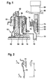
- FIG. 1 includes a dual clutch 12 rotatably connected to the crankshaft 10 ( FIG. 8 ) an internal combustion engine connected housing 60 having a left side of a base plate 61 of the housing arranged first clutch disc 62 of a first clutch K1 ( FIG. 8 ) and a right side of the base plate 61 arranged clutch disc 64 of a second clutch K2 ( FIG. 8 ).
- first clutch disc 62 of a first clutch K1
- K2 FIG. 8
- the clutch disc 64 can be pressed by means of a pressure plate 66 in frictional engagement with the base plate 61, so that from the housing 60 via the clutch disc 64 torque to the second input shaft 18 (FIGS. FIG. 8 ) of the dual-clutch transmission is.
- a pressure plate 66 For axial displacement of the pressure plate 66 serves a plate spring-like trained clutch lever 68 which is supported between the housing 60 and the pressure plate 66 and is shaped so that it moves the clutch automatically in the open position.
- a transmission member 70 is provided, which is supported on one side via a bearing on the clutch lever 68 and at its other end in contact with an actuating lever 72 ,
- the actuating lever 72 abuts against a roller 74, against which it is pressed by a spring 76 which is supported on a machine-fixed stop 78.
- the roller 74 is mounted on a spindle nut 80 which is in threaded engagement with a spindle 82 which is rotationally driven by an electric motor 84.
- an increment sensor 86 is provided, which is connected to an input 44 of the electronic control device 42 (FIG. FIG. 8 ) connected is.
- the electric motor rotates the spindle 82 along which the spindle nut 80 moves linearly, whereby the roller 74 moves along the actuating lever 72 and this according to the inclination, the contact surface of the actuating lever 72 relative to the direction of movement of the roller 74th has, pivoted.
- the entire arrangement is such that the plate-spring-like coupling lever 68 from a closed position of the clutch as a result of its own force, the transfer member 70 to the right in the in FIG. 1 shown position, wherein when a pivoting of the actuating lever 72 in the counterclockwise direction, the idling torque of the electric motor 84 is suppressed and the roller 74 moves under rotation of the spindle 82 upwards.
- the clutch is thus pressed into its closed position and automatically assumes its open position.
- FIG. 2 illustrates the force relationships on the operating lever 72nd
- F 1 denotes the force exerted by the spring 76 on the actuating lever 72.
- F 2 designates the force acting on the actuating lever 72 from the transmission member 70.
- L is the distance between the lines of action of the forces.
- x is the distance of the point of contact between the roller 74 and the operating lever 72 from the line of action of the force F 1 .
- FIG. 4 indicates the transmittable clutch torque M as a function of x-x0.
- xT is the touch point of the clutch in which the torque transmission begins.
- the adjustment range of the spindle nut 80 could be limited by a stop, against which the spindle nut 80 according to FIG. 1 moved upwards. Referencing can be effected by determining the count of the incremental sensor 86 when the spindle nut 80 moves against a stop, not shown, or by applying the force to be applied by the spindle nut 80 (corresponding to the torque to be applied by the electric motor 84) goes.
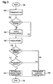
- step 102 a target gear is determined, which in the part of the clutch under consideration ( FIG. 8 ) of the dual-clutch transmission to be inserted.
- step 104 it is determined whether the target gear is already engaged. If this is the case, then the target gear is designed in step 106, in order then to be put back in step 108 after a short waiting time of, for example, 0.1 seconds.
- step 104 If it is determined in step 104 that the target gear is not engaged, the system proceeds directly to step 108. If it is then determined in step 110 that the target gear has been successfully engaged, i. that the respective gear actuator reaches its end position, it can be assumed that the clutch is open, ie the clutch actuator is between x0 and xT, i. that the referencing was successful.
- step 112 Further assurance in the test can be achieved by checking in step 112 whether the input shaft 18 has the size dependent on the vehicle speed for the translation of the target gear.
- step 110 the system proceeds to step 114, in which the plausibility of the reference position determined during the previous referencing is determined and the clutch is released for further operation. Subsequently, the verification process in step 116 is ended.
- step 118 If an error is detected in one of the steps 110 or 112, then in step 118 the reference position is assessed as implausible and the further operation of the clutch is blocked.
- both the absolute position of the transmission actuator and that of the clutch actuator may be unknown.
- step 122 the clutch is referenced by, for example, the electric motor or other actuator in the Kupplungsaktorik after slight operation in the closing direction is put out of service and it is checked whether the Kupplungsaktorik then moves back and possibly against a stop.
- step 124 it is checked whether the clutch or the spindle nut 80 of the FIG. 2 has moved back and possibly against a stop (the rotation of the electric motor has come to a standstill). If this is not the case, another attempt is made to refer to the clutch in the illustrated example by opening, wherein in step 126, the number of the respective tests is counted and opened in each attempt, for example, the clutch additionally by appropriate action on the electric motor with electric motor help and the spindle nut can be moved against the stop. If it is determined in step 128 that a predetermined number of unsuccessful homing attempts has taken place, the corresponding partial transmission of the dual-clutch transmission is no longer actuated in step 130.
- step 124 If step 124 has been completed successfully, i. If it can be assumed that the clutch is open, an attempt is made in step 126 to lay out a gear engaged in the affected partial transmission. If it is determined in step 128 that the gear has been successfully designed, for example, the gear actuator has reached a predetermined position or the speed of the associated input shaft changes in a predetermined manner, the system proceeds to step 130, where it is assumed that the gearbox is not in gear.
- step 132 the clutch is then fully closed and thereby traversed travel determined, for example, from the initial state of the increment counter 86 and its final state when reaching the fully closed position of the clutch.
- the speed of the electric motor or the travel speed of the actuator can be limited or provided in the transmission path between the electric motor and spindle a slip clutch to protect the actuator from overloading, if the entire travel is not available. If it is determined in step 134 that the intended travel path is available, this is considered to be a plausibility check of the referencing (step 124), so that in step 136, normal clutch operation is proceeded.
- steps 128 or 134 are unsuccessful, ie possibly unsuccessful referencing, the system returns to step 122, counting the number of attempts and decommissioning the sub-transmission in step 130 if the number exceeds a predetermined number.
- the total number of attempts can be counted, ie the number of unsuccessful steps 124, 128 and 134 can be added.
- step 124 the position of the clutch actuator may not be changed, so that the clutch is not closed during the subsequent steps, for example.
- step 126 or 128 If it is determined in step 126 or 128 that a gear can be designed, this can be used for a referencing of the gear actuator. If the clutch is not open, the engagement of a gear should not be possible, which can be determined easily.
- the curve of FIG. 7 is about the same FIG. 3 with the difference that the direction of the force to be applied to the spindle nut 80 does not change abruptly when the clutch is open but is approximately 0 over a range L between a value x00 and x0 and only then increases suddenly to close the clutch. This is achieved by a corresponding design of the plant or ramp surface at which the actuating lever 72 is in contact with the roller 74. It is understood that the force to close the clutch and also the force with which the operating lever 72 can be moved beyond the open position need not be constant. In any case, the closing force must be above a predetermined value to ensure that the clutch moves automatically in the open position.
- the clutch moves automatically (electric motor de-energized) from the closed position to the position x0, which is used for homing.
- a plausibility check it is checked whether the spindle nut 80 can be moved by the distance L, ie between x0 and x00, when the electric motor is subjected to current below a predetermined value, ie very small torque. If this is the case, the referencing is considered to be plausible, ie correct.
- it can be checked whether the electric motor stops in each of the intermediate positions between x0 and x00 in the event of a power cut-off, ie no force acts on it from the clutch which adjusts it.
- the exemplary embodiments and devices described may be modified in many ways.
- the clutch does not necessarily have to be part of a dual-clutch transmission.
- the actuation of the clutch can be done hydraulically or otherwise.
- the clutch may be a clutch that moves automatically in the closed position, etc.
Landscapes
- Physics & Mathematics (AREA)
- Engineering & Computer Science (AREA)
- General Engineering & Computer Science (AREA)
- Electromagnetism (AREA)
- Fluid Mechanics (AREA)
- Mechanical Engineering (AREA)
- Control Of Transmission Device (AREA)
- Hydraulic Clutches, Magnetic Clutches, Fluid Clutches, And Fluid Joints (AREA)
Abstract
Description
- Die Erfindung betrifft ein Verfahren und eine Vorrichtung zum Absichern einer Referenzierung einer Inkrementalwegmessung bei einer in einem Fahrzeugantriebsstrang enthaltenen Kupplungsaktorik.
- In Fahrzeugantriebssträngen finden selbsttätig in Abhängigkeit von Betriebsparametern des Antriebstrangs schaltende Schaltgetriebe insbesondere aus Gründen der Verbrauchsminderung zunehmend Verwendung.
-
Figur 8 zeigt einen solchen an sich bekannten automatisierten Fahrzeugantriebsstrang mit einem Doppelkupplungs- bzw. Parallelschaltgetriebe: - Die Kurbelwelle 10 eines beispielsweise als Brennkraftmaschine ausgebildeten Antriebsmotors des Fahrzeugs ist mit einem Gehäuse einer Doppelkupplung 12 verbunden, die zwei getrennt voneinander betätigbare Kupplungen K1 und K2 enthält. Mittels der Kupplung K1 kann die Kurbelwelle 10 mit einer ersten Eingangswelle 14 eines insgesamt mit 16 bezeichneten Doppelkupplungsgetriebes gekuppelt werden. Mittels der Kupplung K2 kann die Kurbelwelle 10 mit einer zweiten Eingangswelle 18 des Doppelkupplungsgetriebes 16 gekuppelt werden. Die zweite Eingangswelle 18 ist hohl und die erste Eingangswelle 14 erstreckt sich durch die zweite Eingangswelle 18 hindurch.
- Mit jeder der Eingangswellen 14 und 18 sind Zahnräder drehfest verbunden, die mit Zahnrädern kämmen, die auf parallel zu den Eingangswellen 14 und 18 angeordneten Ausgangswellen 20 und 22 axial fest, jedoch drehbar gelagert sind. Mit jeder der Ausgangswellen 20 und 22 ist starr ein Ausgangsritzel 24 bzw. 26 verbunden, das gegebenenfalls über Zwischenübersetzungen auf eine Antriebswelle zum Antreiben wenigstens eines Fahrzeugrades wirkt.
- Die auf den Ausgangswellen 20 bzw. 22 gelagerten Zahnräder können jeweils über Schaltmuffen 28, 30, 32 und 34 drehfest mit der jeweiligen Ausgangswelle gekuppelt werden. Durch die drehfeste Kupplung eines auf einer Ausgangswelle gelagerten Zahnrades mit der jeweiligen Ausgangswelle werden Gänge geschaltet, die in
Figur 8 mit 1, 2, 3, 4, 5, 6, 7 und R bezeichnet sind. Der Einfachheit halber sind Zahnradpaarungen zum Schalten des Rückwärtsganges R nicht eingezeichnet. - Die mit der zweiten Eingangswelle 18 drehfest verbundenen Zahnräder bilden zusammen mit den mit ihnen kämmenden Zahnrädern der Ausgangswellen ein erstes Teilgetriebe 36, mit dem die ungeraden Gänge geschaltet werden. Die mit der ersten Ausgangswelle 14 drehfest verbundenen Zahnräder bilden zusammen mit den jeweiligen Gegenzahnrädern ein zweites Teilgetriebe 38, mit dem die geraden Gänge und der Rückwärtsgang geschaltet werden.
- Zum Bewegen einer Schaltmuffe längs der zugehörigen Ausgangswelle sind parallel zur Bewegbarkeit der Schaltmuffen beweglich geführte Schaltschienen vorgesehen, die beispielsweise über doppelt wirkende Schaltzylinder hin und her bewegbar sind. In
Figur 8 ist die der Schaltmuffe 34 zugeordnete Schaltschiene mit 40 bezeichnet. - Die Steuerung des Doppelkupplungsgetriebes 16 erfolgt mit Hilfe einer elektronischen Steuereinrichtung 42, deren Eingänge 44 mit nicht dargestellten Sensoren zur Erfassung von für den Betrieb des Doppelkupplungsgetriebes maßgeblichen Betriebsparametern verbunden sind. Ausgänge der Steuereinrichtung 42 sind mit einer Kupplungsaktorik 46, 48 zum Betätigen der Kupplungen K1 und K2 sowie einer Schaltaktorik 50, 52, 54 und 56 zum Betätigen jeweils einer Schaltschiene verbunden.
- Aufbau und Funktion des beschriebenen Doppelkupplungsgetriebes, das vielfältig abgewandelt werden kann, sind an sich bekannt und werden daher nicht näher erläutert.
- Die Kupplungsaktoren 46 bzw. 48 enthalten beispielsweise einen Elektromotor, dessen Drehung in eine Bewegung eines Kupplungshebels umgesetzt wird, mit dem das Drehmomentübertragungsvermögen der Kupplung eingestellt wird. Eine genaue Kenntnis des Drehmomentübertragungsvermögens der Kupplung und damit der Stellung des Kupplungshebels ist für eine genaue Steuerung bzw. Regelung des Anfahrens und von Schaltvorgängen wichtig.
- Insbesondere wenn der Kupplungsaktor durch einen Elektromotor gebildet ist, wird die Drehung einer Welle des Elektromotors, entsprechend der ein mit dem Kupplungshebel bewegungsübertragend verbundenes Betätigungsglied bewegt wird, von einem Inkrementsensor erfasst. Mit einem solchen Inkrementsensor können keine Absolutstellungen des Betätigungsgliedes erfasst werden, sondern nur Stellungsänderungen, so dass es erforderlich ist, die Absolutstellung des Betätigungsgliedes bzw. die Drehstellung der Ausgangswelle des Elektromotors über eine Referenzierung zu ermitteln und beispielsweise nach einem Reset oder im Laufe von auftretendem Verschleiß zu aktualisieren.
- Aus der
DE 44 33 825 C2 ist eine Stelleinrichtung für eine Kraftfahrzeug-Reibungskupplung bekannt, bei der die Ausgangswelle eines Elektromotors ein Segmentzahnrad antreibt, an dem ein Betätigungsglied für die Kupplung gelagert ist. Der Verdrehbereich des Segmentzahnrades ist durch Anschläge begrenzt, die zum Referenzieren angefahren werden können. Auf diese Weise kann die Absolutstellung des Betätigungsgliedes ermittelt werden, von der aus der Verstellweg mittels eines Inkrementzählers erfasst werden kann. - Aus der
DE 100 27 330 A1 ist eine Vorrichtung zum Schalten eines Getriebes bekannt, bei der ein Elektromotor, dessen Drehstellung mittels eines Inkrementsensors erfasst wird, ein Betätigungsglied des Getriebes antreibt, das in einer Endstellung gegen einen Anschlag bewegt werden kann. Das Betätigungsglied ist zusätzlich mit einer Oberflächenprofilierung versehen, in die ein Feder belastetes Abtastbauteil eingreift. Die Profilierung des Betätigungsgliedes ist derart, dass die zum Verstellen des Betätigungselements erforderliche Kraft von der Relativstellung zwischen der Oberflächenprofilierung und dem Abtastbauteil abhängt. Die Steilheit von Formflächen der Profilierung kann derart sein, dass die durch elastische Vorspannung des Abtastbauteils auf das Betätigungsglied aufgebrachte Kraft in Teilbereichen größer ist als das Haltemoment des Elektromotors, so dass bei geringer Spannungsbeaufschlagung des Elektromotors ermittelt werden kann, ob sich das Betätigungsglied in einem vorbestimmten Stellbereich befindet. - Referenzierungen, die dadurch erfolgen, dass ein Betätigungsglied gegen einen Anschlag bewegt wird und die durch Plausibilisierungsroutinen abgesichert werden, indem nach der eigentlichen Referenzierung Lastprofile beispielsweise eines Elektromotors aufgenommen werden, sind toleranzanfällig und stellen unter Umständen Beschränkungen für die Hardware-Auslegung der Kupplungsaktorik dar.
- Der Erfindung liegt die Aufgabe zugrunde, ein Verfahren und eine Vorrichtung zum Absichern einer Referenzierung einer Inkrementalwegmessung bei einer in einem Fahrzeugantriebsstrang enthaltenen Kupplungsaktorik anzugeben, bei dem bzw. der ein hohes Maß an Sicherheit der Referenzierung erzielt wird.
- Die vorgenannte Aufgabe wird mit den Merkmalen der beigefügten unabhängigen Ansprüche gelöst. Die jeweiligen Unteransprüche sind auf vorteilhafte Durchführungsformen bzw. Ausführungsformen und Weiterbildungen des erfindungsgemäßen Verfahrens bzw. der erfindungsgemäßen Vorrichtung gerichtet.
- Erfindungsgemäß wird bei einem Verfahren zum Absichern einer Referenzierung einer Inkrementalwegmessung bei einer in einem Fahrzeugantriebsstrang enthaltenen Kupplungsaktorik bei nach einer Referenzierung in einer vorbestimmten Stellung befindlicher Kupplungsaktorik eine Getriebeaktorik zum Schalten eines in dem Antriebstrang enthaltenen Schaltgetriebes in vorbestimmter Weise betätigt und aus einer auf eine Referenzierung folgenden Betätigung der Getriebeaktorik oder einer auf eine Referenzierung folgenden Betätigung der Kupplungsaktorik die Referenzierung als einwandfrei oder fehlerhaft klassifiziert.
- Bei einer Durchführungsform des erfindungsgemäßen Verfahrens wird die Kupplungsaktorik zum Referenzieren in eine dem voll geöffneten Zustand der Kupplung entsprechende Stellung bewegt, mittels der Getriebeaktorik ein Gang eingelegt und die Einlegbarkeit des Ganges als einwandfreie Referenzierung gewertet.
- Bei der vorgenannten Durchführungsform wird vorteilhafterweise beim Einlegen des Ganges überprüft, ob sich die Eingangswelle des Getriebes mit einer der Übersetzung des eingelegten Ganges entsprechenden Drehzahl dreht.
- Bei einer weiteren Durchführungsform des erfindungsgemäßen Verfahrens wird die Kupplungsaktorik zum Referenzieren in eine dem voll geöffneten Zustand der Kupplung entsprechende Stellung bewegt und nachfolgend überprüft, ob ein eingelegter Gang ausgelegt werden kann und die Auslegbarkeit des Ganges als einwandfreie Referenzierung gewertet.
- Bevorzugt wird bei der vorgenannten Durchführungsform, nach dem Auslegen des Ganges die Kupplungsaktorik derart betätigt, dass sie einen vorbestimmten maximalen Verfahrweg durchfährt und das Vorhandensein dieses maximalen Verfahrweges als einwandfreie Referenzierung gewertet.
- Bei einem weiteren erfindungsgemäßen Verfahren zum Absichern einer Referenzierung einer Inkrementalwegmessung bei einer in einem Fahrzeugantriebsstrang enthaltenen Kupplungsaktorik, wobei die Kupplungsaktorik und die Kupplung derart ausgebildet sind, dass im voll geöffneten Zustand der Kupplung von der Kupplungsaktorik über eine vorbestimmte Strecke auf die Kupplung eine unterhalb eines vorbestimmten Wertes liegende Schwellkraft ausgeübt wird, wird die Kupplungsaktorik zum Referenzieren in eine dem voll geöffneten Zustand der Kupplung entsprechende Stellung bewegt und anschließend überprüft, ob die Kupplungsaktorik über die vorbestimmte Strecke bewegbar ist, ohne dass die Schwellkraft überschritten wird, und die Bewegbarkeit der Kupplungsaktorik über die vorbestimmte Strecke ohne Überschreiten der Schwellkraft als einwandfreie Referenzierung gewertet.
- Bei einer erfindungsgemäßen Vorrichtung zum Absichern einer Referenzierung einer Inkrementalwegmessung bei einer in einem Fahrzeugantriebsstrang enthaltenen Kupplungsaktorik, welcher Fahrzeugantriebsstrang einen Antriebsmotor, ein von einer Getriebeaktorik betätigbares Schaltgetriebe, eine zwischen dem Antriebsmotor und dem Getriebe angeordnete, von der Kupplungsaktorik betätigte Kupplung und eine elektronische Steuereinrichtung enthält, die die Kupplungsaktorik und die Getriebeaktorik in Abhängigkeit von von Sensoren erfassten Betriebsparametern des Antriebsstrangs steuert, steuert die Steuereinrichtung die Kupplungsaktorik und die Getriebeaktorik entsprechend einem der vorgenannten Verfahren.
- Die Kupplungsaktorik kann einen Betätigungshebel enthalten, der um ein von einem Aktor bewegbares Stützglied schwenkbar ist und von einer Feder in Anlage an das Stützglied und ein Betätigungselement der Kupplung gedrängt wird.
- Das Stützglied ist vorteilhaft linear etwa in Längsrichtung des Betätigungshebels bewegbar und der Betätigungshebel ist in seiner Längsrichtung unterschiedlich zur Bewegbarkeitsrichtung des Stützgliedes geneigt.
- Die Kupplung kann als eine sich selbsttätig öffnende Kupplung ausgebildet sein.
- Die Erfindung ist besonders vorteilhafterweise für Kupplungen einsetzbar, die jeweils eine der beiden Kupplungen eines Doppelkupplungsgetriebes sind, wobei das der Kupplung zugeordnete Getriebe jeweils eines von zwei Teilgetrieben des Doppelkupplungsgetriebes ist.
- Die Erfindung wird im Folgenden anhand schematischer Zeichnungen beispielsweise und mit weiteren Einzelheiten erläutert.
- In den Figuren stellen dar:
- Figur 1
- einen Halblängsschnitt durch eine Doppelkupplung;
- Figur 2
- eine Prinzipdarstellung von Teilen der
Figur 1 ; - Figur 3
- eine Kraftwegkennlinie einer Kupplungsaktorik;
- Figur 4
- eine Kupplungsmoment-Wegkennlinie;
- Figur 5
- ein Flussdiagramm zur Erläuterung eines erfindungsgemäßen Verfahrens;
- Figur 6
- ein Flussdiagramm einer weiteren Durchführungsform eines erfindungsgemäßen Verfahrens;
- Figur 7
- eine Kraftwegkennlinie einer weiteren Ausführungsform einer Kupplungsaktorik und
- Figur 8
- ein bereits erläutertes Schema eines an sich bekannten Doppelkupplungsgetriebes.
- Gemäß
Figur 1 enthält eine Doppelkupplung 12 ein drehfest mit der Kurbelwelle 10 (Figur 8 ) einer Brennkraftmaschine verbundenes Gehäuse 60 mit einer linksseitig einer Grundplatte 61 des Gehäuses angeordneten ersten Kupplungsscheibe 62 einer ersten Kupplung K1 (Figur 8 ) und einer rechtsseitig der Grundplatte 61 angeordneten Kupplungsscheibe 64 einer zweiten Kupplung K2 (Figur 8 ). Im Folgenden wird nur die Betätigung der rechtsseitigen Kupplungsscheibe 64 näher erläutert. Die Betätigung der linksseitigen Kupplungsscheibe 62 erfolgt in entsprechender Weise. - Die Kupplungsscheibe 64 ist mit Hilfe einer Andrückplatte 66 in reibschlüssige Anlage an die Grundplatte 61 drückbar, so dass von dem Gehäuse 60 über die Kupplungsscheibe 64 Drehmoment auf die zweite Eingangswelle 18 (
Figur 8 ) des Doppelkupplungsgetriebes übertragbar ist. Zur axialen Verschiebung der Andrückplatte 66 dient ein tellerfederartig ausgebildeter Kupplungshebel 68, der sich zwischen dem Gehäuse 60 und der Andrückplatte 66 abstützt und derart geformt ist, dass er die Kupplung selbsttätig in Offenstellung bewegt. - Zum Bewegen des Kupplungshebels 68 derart, dass die Andrückplatte 66 die Kupplungsscheibe 64 gegen die Gehäusegrundplatte drängt, ist ein Übertragungsglied 70 vorgesehen, das sich an einer Seite über ein Lager an dem Kupplungshebel 68 abstützt und an seinem anderen Ende in Anlage an einem Betätigungshebel 72 ist.
- Der Betätigungshebel 72 liegt an einer Rolle 74 an, gegen die er von einer Feder 76 angepresst wird, die sich an einem maschinenfesten Anschlag 78 abstützt.
- Die Rolle 74 ist an einer Spindelmutter 80 gelagert, die in Gewindeeingriff mit einer Spindel 82 ist, die von einem Elektromotor 84 drehangetrieben wird. Zur Erfassung der Drehstellung eines sich bei Betätigung des Elektromotors 84 drehenden Bauteils ist ein Inkrementsensor 86 vorgesehen, der mit einem Eingang 44 der elektronischen Steuereinrichtung 42 (
Figur 8 ) verbunden ist. - Zum Betätigen des Kupplungshebels 68 dreht der Elektromotor die Spindel 82, längs der sich dadurch die Spindelmutter 80 linear bewegt, wodurch sich die Rolle 74 längs des Betätigungshebels 72 bewegt und diesen entsprechend der Neigung, die die Anlagefläche des Betätigungshebels 72 relativ zur Bewegungsrichtung der Rolle 74 hat, verschwenkt.
- Die gesamte Anordnung ist derart, dass der tellerfederartig ausgebildete Kupplungshebel 68 aus einer geschlossenen Stellung der Kupplung in Folge seiner Eigenkraft das Übertragungsglied 70 nach rechts in die in
Figur 1 gezeigte Stellung bewegt, wobei bei einer Verschwenkung des Betätigungshebels 72 in Gegenuhrzeigerrichtung das Leerlaufmoment des Elektromotors 84 überdrückt wird und sich die Rolle 74 unter Drehung der Spindel 82 aufwärts bewegt. Die Kupplung wird somit in ihre Schließstellung gedrückt und nimmt selbsttätig ihre Offenstellung ein. -
Figur 2 verdeutlicht die Kraftverhältnisse am Betätigungshebel 72. - F1 bezeichnet die Kraft, die von der Feder 76 auf den Betätigungshebel 72 ausgeübt wird. F2 bezeichnet die vom Übertragungsglied 70 her auf den Betätigungshebel 72 wirkende Kraft. L ist der Abstand zwischen den Wirklinien der Kräfte. x ist der Abstand des Berührungspunktes zwischen der Rolle 74 und dem Betätigungshebel 72 von der Wirklinie der Kraft F1.
- Es gilt:

- Im stromlosen Zustand des Elektromotors 84 stellt sich das System unter Wirkung der Kraft des Kupplungshebels 68 in die dargestellte Stellung.
- Für die auf die Spindelmutter 80 von der Spindel 82 aufzubringende Kraft gilt die in
Figur 3 dargestellte Beziehung, wobei F die auf die Spindelmutter 80 aufzubringende Axialkraft darstellt und die Abszisse (x-x0) darstellt, wobei x0 den Wert von x im stromlosen Zustand angibt, d.h. bei offener Kupplung. -
Figur 4 gibt das übertragbare Kupplungsmoment M in Abhängigkeit von x-x0 an. xT ist der Tastpunkt der Kupplung, in dem die Momentenübertragung beginnt. - Wie aus
Figur 3 ersichtlich, gibt der Punkt x=x0 die Stellbereichsgrenze an, bei deren Überfahren sich die Richtung der von der Spindelmutter 80 aufzubringenden Kraft ändert und sich entsprechend das vom Elektromotor 84 aufzubringende Drehmoment ändert. Der Stellbereich der Spindelmutter 80 könnte durch einen Anschlag begrenzt werden, gegen den sich die Spindelmutter 80 gemäßFigur 1 nach oben bewegt. Eine Referenzierung kann dadurch erfolgen, dass der Zählstand des Inkrementalsensors 86 ermittelt wird, wenn sich die Spindelmutter 80 beim Öffnen der Kupplung gegen einen nicht dargestellten Anschlag bewegt oder aber die von der Spindelmutter 80 aufzubringende Kraft (entsprechend dem vom Elektromotor 84 aufzubringenden Drehmoment) durch 0 geht. - Im Folgenden wird eine im Anschluss an eine Referenzierung durchzuführende Plausibilisierung bzw. Absicherung der Referenzierung anhand des Flussdiagramms gemäß
Figur 5 erläutert. Eine Plausibilisierung der Referenzposition ist zweckmäßig, da dadurch die Möglichkeit ausgeschlossen werden kann, dass ein unerwarteter Anschlag in Richtung Öffnen die Aktoreinrichtung bzw. den Elektromotor 84 in einer anderen Position als x=x0 zum Stehen gebracht hat oder aber, falls ohne Anschlag gearbeitet wird, dass ein Fehler im System, beispielsweise ein Bruch der Tellerfeder des Kupplungshebels 68 erkannt wird, wodurch die Kraft zum Bewegen der Spindelmutter Null würde, was eine fehlerhafte Referenzierung nach sich ziehen würde. - Sei angenommen, dass im Schritt 100 ein Überprüfungsprogramm startet. Im Schritt 102 wird ein Zielgang bestimmt, der in dem das der betrachteten Kupplung entsprechenden Teilgetriebe (
Figur 8 ) des Doppelkupplungsgetriebes eingelegt werden soll. - Im Schritt 104 wird bestimmt, ob der Zielgang bereits eingelegt ist. Ist dies der Fall, so wird der Zielgang im Schritt 106 ausgelegt, um dann im Schritt 108 nach einer kurzen Wartezeit von beispielsweise 0,1 Sekunden wieder eingelegt zu werden.
- Wenn im Schritt 104 festgestellt wird, dass der Zielgang nicht eingelegt wird, geht das System direkt zum Schritt 108. Wenn im Schritt 110 anschließend festgestellt wird, dass der Zielgang erfolgreich eingelegt wurde, d.h. dass der jeweilige Getriebeaktor seine Endlage erreicht, so ist davon auszugehen, dass die Kupplung offen ist, die Kupplungsaktorik sich also zwischen x0 und xT befindet, d.h. dass die Referenzierung erfolgreich war.
- Eine weitere Sicherheit bei der Prüfung kann dadurch erreicht werden, dass im Schritt 112 überprüft wird, ob die Eingangswelle 18 die zu der Übersetzung des Zielgangs entsprechende, von der Fahrzeuggeschwindigkeit abhängige Größe hat.
- Ist in den Schritten 110 und 112 jeweils ein Ja festgestellt worden, so schreitet das System zum Schritt 114 weiter, in dem die Plausibilität der bei der vorherigen Referenzierung ermittelten Referenzposition festgestellt wird und die Kupplung für einen weiteren Betrieb freigegeben wird. Anschließend wird der Überprüfungsvorgang im Schritt 116 beendet.
- Wird in einem der Schritte 110 oder 112 ein Fehler festgestellt, so wird im Schritt 118 die Referenzposition als unplausibel bewertet und der weitere Betrieb der Kupplung gesperrt.
- Anhand der
Figur 6 wird eine weitere Möglichkeit erläutert, eine Referenzierung der Kupplungsaktorik abzusichern. - Sei angenommen, dass das System beispielsweise nach einem Reset im Schritt 120 startet, wobei nach einem Reset sowohl die Absolutposition der Getriebeaktorik als auch der der Kupplungsaktorik unbekannt sein kann.
- Im Schritt 122 wird die Kupplung referenziert, indem beispielsweise der Elektromotor oder ein sonstiger Aktor in der Kupplungsaktorik nach geringer Betätigung in Schließrichtung außer Betrieb gesetzt wird und überprüft wird, ob die Kupplungsaktorik sich anschließend zurück und gegebenenfalls gegen einen Anschlag bewegt. Im Schritt 124 wird überprüft, ob sich die Kupplung bzw. die Spindelmutter 80 der
Figur 2 zurück und gegebenenfalls gegen einen Anschlag bewegt hat (die Drehung des Elektromotors zum Stillstand gekommen ist). Ist dies nicht der Fall, so erfolgt ein weiterer Versuch, die Kupplung im dargestellten Beispiel durch Öffnen zu referenzieren, wobei im Schritt 126 die Anzahl der jeweiligen Versuche gezählt wird und beim jeweiligen Versuch beispielsweise die Kupplung zusätzlich durch entsprechende Beaufschlagung des Elektromotors mit elektromotorischer Hilfe geöffnet und die Spindelmutter gegen den Anschlag bewegt werden kann. Wenn im Schritt 128 festgestellt wird, dass eine vorbestimmte Anzahl erfolgloser Referenzierungsversuche stattgefunden hat, wird das entsprechende Teilgetriebe des Doppelkupplungsgetriebes im Schritt 130 nicht mehr betätigt. - Wenn der Schritt 124 erfolgreich abgeschlossen wurde, d.h. davon ausgegangen werden kann, dass die Kupplung offen ist, wird im Schritt 126 versucht, einen in dem betroffenen Teilgetriebe eingelegten Gang auszulegen. Wenn im Schritt 128 festgestellt wird, dass der Gang erfolgreich ausgelegt wurde, beispielsweise die Getriebeaktorik eine vorbestimmte Stellung erreicht hat oder die Drehzahl der zugehörigen Eingangswelle sich in vorbestimmter Weise ändert, geht das System zum Schritt 130 weiter, bei dem davon ausgegangen wird, dass in dem Getriebe kein Gang eingelegt ist.
- Im Schritt 132 wird anschließend die Kupplung voll geschlossen und der dabei durchfahrene Verfahrweg festgestellt, beispielsweise aus dem anfänglichen Stand des Inkrementzählers 86 und dessen Endstand beim Erreichen der voll geschlossenen Stellung der Kupplung. Dabei kann die Drehzahl des Elektromotors bzw. die Verfahrgeschwindigkeit der Aktorik begrenzt werden oder im Übertragungsweg zwischen Elektromotor und Spindel eine Rutschkupplung vorgesehen sein, um die Aktorik vor einer Überlastung zu schützen, falls der gesamte Verfahrweg nicht zur Verfügung steht. Wenn im Schritt 134 festgestellt wird, dass der vorgesehene Verfahrweg verfügbar ist, wird dies als Plausibilisierung der Referenzierung (Schritt 124) gewertet, so dass in Schritt 136 auf normalen Kupplungsbetrieb übergegangen wird. Bei Erfolglosigkeit der Schritte 128 oder 134, d.h. möglicherweise nicht erfolgreicher Referenzierung, geht das System jeweils zum Schritt 122 zurück, wobei die Anzahl der Versuche gezählt wird und das Teilgetriebe im Schritt 130 stillgelegt wird, wenn die Anzahl eine vorbestimmte Zahl überschreitet. Dabei können die Versuche insgesamt gezählt werden, d.h. die Anzahl der erfolglosen Schritte 124, 128 und 134 kann addiert werden.
- Es versteht sich, dass nach einer vermeintlich erfolgreichen Referenzierung im Schritt 124 die Stellung der Kupplungsaktorik nicht verändert werden darf, damit die Kupplung während der nachfolgenden Schritte beispielsweise nicht geschlossen wird.
- Wenn im Schritt 126 bzw. 128 festgestellt wird, dass ein Gang ausgelegt werden kann, kann dies für ein Referenzieren der Getriebeaktorik genutzt werden. Wenn die Kupplung dabei nicht offen ist, sollte das Einlegen eines Ganges nicht möglich sein, was ohne weiteres festgestellt werden kann.
- Im Folgenden wird anhand der
Figur 7 eine weitere Möglichkeit zur Plausibilisierung bzw. Überprüfung einer Referenzierung erläutert: - Die Kurve der
Figur 7 entspricht etwa derFigur 3 mit dem Unterschied, dass sich die Richtung der auf die Spindelmutter 80 aufzubringenden Kraft bei geöffneter Kupplung nicht sprunghaft ändert sondern über einen Bereich L zwischen einem Wert x00 und x0 näherungsweise 0 ist und erst dann sprunghaft zunimmt, um die Kupplung zu schließen. Dies wird durch eine entsprechende Gestaltung der Anlagen- bzw. Rampenfläche erreicht, an der der Betätigungshebel 72 in Anlage an der Rolle 74 ist. Es versteht sich, dass die Kraft zum Schließen der Kupplung und auch die Kraft, mit der der Betätigungshebel 72 über die Öffnungsstellung hinaus bewegt werden kann, nicht konstant sein müssen. In jedem Fall muss die Schließkraft über einem vorbestimmten Wert liegen, damit sichergestellt ist, dass sich die Kupplung selbsttätig in Offenstellung bewegt. - Die Gestaltung des Betätigungshebels 72 derart, dass sich ein Kraftverlauf gemäß
Figur 7 ergibt, kann folgendermaßen zum Plausibilisieren genutzt werden: - Die Kupplung bewegt sich selbsttätig (Elektromotor stromlos) aus der Schließstellung in die Position x0, die zum Referenzieren benutzt wird. Für eine Plausibilisierung wird überprüft, ob sich die Spindelmutter 80 bei Beaufschlagung des Elektromotors mit unterhalb einem vorbestimmten Wert liegendem Strom, d.h. sehr kleinem Drehmoment, um die Strecke L, d.h. zwischen x0 und x00 bewegen lässt. Ist dies der Fall, so wird die Referenzierung als plausibel, d.h. richtig angenommen. Zusätzlich kann überprüft werden, ob der Elektromotor in jeder der Zwischenstellungen zwischen x0 und x00 bei Stromabschaltung stehen bleibt, d.h. von der Kupplung her keine Kraft auf ihn einwirkt, die ihn verstellt.
- Die beispielhaft beschriebenen Ausführungsformen und Vorrichtungen können in vielfältiger Weise abgeändert werden. Die Kupplung muss nicht zwangsläufig Bestandteil eines Doppelkupplungsgetriebes sein. Die Betätigung der Kupplung kann hydraulisch oder in anderer Weise erfolgen. Die Kupplung kann eine Kupplung sein, die sich selbsttätig in Schließstellung bewegt usw.
-
10 Kurbelwelle 72 Betätigungshebel 12 Doppelkupplung 74 Rolle 14 erste Eingangswelle 76 Feder 16 Doppelkupplungsgetriebe 78 Anschlag 18 zweite Eingangswelle 80 Spindelmutter 20 Ausgangswelle 82 Spindel 22 Ausgangswelle 84 Elektromotor 24 Ausgangsritzel 86 Inkrementsensor 26 Ausgangsritzel 100 bis 136 Verfahrensschritte 28 Schaltmuffe 30 Schaltmuffe 32 Schaltmuffe F Axialkraft 34 Schaltmuffe F1 Kraft 36 erstes Teilgetriebe F2 Kraft 38 zweites Teilgetriebe K1 Kupplung 40 Schaltschiene K2 Kupplung 42 elektronische Steuereinrichtung L Abstand 44 Eingänge M Kupplungsmoment 46 Kupplungsaktor R Gang 48 Kupplungsaktor x Abstand 50 Schaltaktor xT Tastpunkt 52 Schaltaktor 54 Schaltaktor 56 Schaltaktor 60 Gehäuse 61 Grundplatte 62 Kupplungsscheibe 64 Kupplungsscheibe 66 Andrückplatte 68 Kupplungshebel 70 Übertragungsglied
Claims (11)
- Verfahren zum Absichern einer Referenzierung einer Inkrementalwegmessung bei einer in einem Fahrzeugantriebsstrang enthaltenen Kupplungsaktorik, bei welchem Verfahren bei nach einer Referenzierung in einer vorbestimmten Stellung befindlicher Kupplungsaktorik eine Getriebeaktorik zum Schalten eines in dem Antriebsstrang enthaltenen Schaltgetriebes in vorbestimmter Weise betätigt wird und aus einer auf eine Referenzierung folgenden Betätigung der Getriebeaktorik oder einer auf eine Referenzierung folgenden Betätigung der Kupplungsaktorik die Referenzierung als einwandfrei oder fehlerhaft klassifiziert wird.
- Verfahren nach Anspruch 1, wobei die Kupplungsaktorik zum Referenzieren in eine dem voll geöffneten Zustand der Kupplung entsprechende Stellung bewegt wird, mittels der Getriebeaktorik ein Gang eingelegt wird und die Einlegbarkeit des Ganges als einwandfreie Referenzierung gewertet wird.
- Verfahren nach Anspruch 2, wobei beim Einlegen des Ganges überprüft wird, ob sich die Eingangswelle des Getriebes mit einer der Übersetzung des eingelegten Ganges entsprechenden Drehzahl dreht.
- Verfahren nach Anspruch 1, wobei die Kupplungsaktorik zum Referenzieren in eine dem voll geöffneten Zustand der Kupplung entsprechende Stellung bewegt wird und nachfolgend überprüft wird, ob ein eingelegter Gang ausgelegt werden kann und die Auslegbarkeit des Ganges als einwandfreie Referenzierung gewertet wird.
- Verfahren nach Anspruch 4, wobei nach dem Auslegen des Ganges die Kupplungsaktorik derart betätigt wird, dass sie einen vorbestimmten maximalen Verfahrweg durchfährt und das Vorhandensein dieses maximalen Verfahrwegs als einwandfreie Referenzierung gewertet wird.
- Verfahren zum Absichern einer Referenzierung einer Inkrementalwegmessung bei einer in einem Fahrzeugantriebsstrang enthaltenen Kupplungsaktorik, wobei die Kupplungsaktorik und die Kupplung derart ausgebildet sind, dass im voll geöffneten Zustand der Kupplung von der Kupplungsaktorik über eine vorbestimmte Strecke auf die Kupplung eine unterhalb eines vorbestimmten Wertes liegende Schwellkraft ausgeübt wird, bei welchem Verfahren die Kupplungsaktorik zum Referenzieren in eine dem voll geöffneten Zustand der Kupplung entsprechende Stellung bewegt wird und anschließend überprüft wird, ob die Kupplungsaktorik über die vorbestimmte Strecke bewegbar ist, ohne dass die Schwellkraft überschritten wird, und die Bewegbarkeit der Kupplungsaktorik über die vorbestimmte Strecke ohne Überschreiten der Schwellkraft als einwandfreie Referenzierung gewertet wird.
- Vorrichtung zum Absichern einer Referenzierung einer Inkrementalwegmessung bei einer in einem Fahrzeugantriebsstrang enthaltenen Kupplungsaktorik, welcher Fahrzeugantriebsstrang einen Antriebsmotor, ein von einer Getriebeaktorik (50, 52, 54, 56) betätigbares Schaltgetriebe (16), eine zwischen dem Antriebsmotor und dem Getriebe angeordnete, von der Kupplungsaktorik (46, 48) betätigte Kupplung (K1, K2) und eine elektronische Steuereinrichtung (42) enthält, die die Kupplungsaktorik und die Getriebeaktorik in Abhängigkeit von von Sensoren erfassten Betriebsparametern des Antriebsstrangs steuert, wobei die Steuereinrichtung die Kupplungsaktorik und die Getriebeaktorik entsprechend einem Verfahren nach einem der Ansprüche 1 bis 6 steuert.
- Vorrichtung nach Anspruch 7, wobei die Kupplungsaktorik einen Betätigungshebel (72) enthält, der um ein von einem Aktor (84) bewegbares Stützglied (74) schwenkbar ist und von einer Feder (76) in Anlage an das Stützglied und ein Betätigungselement (70) der Kupplung gedrängt wird.
- Vorrichtung nach Anspruch 8, wobei das Stützglied (74) linear etwa in Längsrichtung des Betätigungshebels (72) bewegbar ist und der Betätigungshebel in seiner Längsrichtung unterschiedlich zur Bewegbarkeitsrichtung des Stützgliedes geneigt ist.
- Vorrichtung nach Anspruch 8 oder 9, wobei die Kupplung als sich selbsttätig öffnende Kupplung ausgebildet ist.
- Vorrichtung nach einem der Ansprüche 8 bis 11, wobei die Kupplung eine der beiden Kupplungen (K1, K2) eines Doppelkupplungsgetriebes (16) ist und das Getriebe eines von zwei Teilgetrieben des Doppelkupplungsgetriebes ist.
Applications Claiming Priority (1)
| Application Number | Priority Date | Filing Date | Title |
|---|---|---|---|
| DE102006061547 | 2006-12-27 |
Publications (3)
| Publication Number | Publication Date |
|---|---|
| EP1939481A2 true EP1939481A2 (de) | 2008-07-02 |
| EP1939481A3 EP1939481A3 (de) | 2010-06-09 |
| EP1939481B1 EP1939481B1 (de) | 2011-07-27 |
Family
ID=39199966
Family Applications (1)
| Application Number | Title | Priority Date | Filing Date |
|---|---|---|---|
| EP07024185A Not-in-force EP1939481B1 (de) | 2006-12-27 | 2007-12-13 | Verfahren und Vorrichtung zum Absichern einer Referenzierung einer Inkrementalwegmessung bei einer Kupplungsaktorik |
Country Status (2)
| Country | Link |
|---|---|
| EP (1) | EP1939481B1 (de) |
| AT (1) | ATE518073T1 (de) |
Cited By (4)
| Publication number | Priority date | Publication date | Assignee | Title |
|---|---|---|---|---|
| WO2010020520A1 (de) * | 2008-08-22 | 2010-02-25 | Robert Bosch Gmbh | Verfahren zum erfassen eines verschleisses einer motortrennkupplung |
| EP2221498A3 (de) * | 2009-02-23 | 2011-12-28 | GETRAG Getriebe- und Zahnradfabrik Hermann Hagenmeyer GmbH & Cie KG | Kupplungsansteuerungsverfahren |
| WO2015149793A3 (de) * | 2014-04-03 | 2015-11-26 | Schaeffler Technologies AG & Co. KG | VERFAHREN ZUM REFERENZIEREN EINES NULLPUNKTES EINER SELBSTSCHLIEßENDEN KUPPLUNG IN EINEM KRAFTFAHRZEUG |
| CN112334674A (zh) * | 2018-06-13 | 2021-02-05 | 康斯博格汽车部件集团股份公司 | 电驱动式离合器致动器 |
Citations (2)
| Publication number | Priority date | Publication date | Assignee | Title |
|---|---|---|---|---|
| DE4435825A1 (de) | 1994-10-07 | 1996-04-11 | Adolf Wuerth Gmbh & Co Kg | Schubladenfach mit einer arretierbaren Schublade |
| DE10027330A1 (de) | 1999-06-08 | 2000-12-14 | Luk Lamellen & Kupplungsbau | Verfahren zum Betreiben einer Drehmoment-Übertragungseinrichtung |
Family Cites Families (7)
| Publication number | Priority date | Publication date | Assignee | Title |
|---|---|---|---|---|
| DE19605722C2 (de) * | 1996-02-16 | 1998-07-09 | Mannesmann Sachs Ag | Einrichtung zur Funktionsüberprüfung einer elektrisch steuerbaren Aktuatoranordnung |
| DE19953292A1 (de) * | 1999-11-05 | 2001-05-10 | Mannesmann Sachs Ag | Verfahren zum Einlernen eines Aktuators für eine Kupplung und/oder ein Getriebe in einem Antriebsstrang |
| WO2003008779A2 (de) * | 2001-07-18 | 2003-01-30 | Luk Lamellen Und Kupplungsbau Beteiligungs Kg | Verfahren zur durchführung einer diagnose in kraftfahrzeugen |
| DE502004002490D1 (de) * | 2003-02-20 | 2007-02-15 | Luk Lamellen & Kupplungsbau | Verfahren und Vorrichtung zur Steuerung einer Kupplung |
| DE10313483B4 (de) * | 2003-03-26 | 2019-12-19 | Zf Friedrichshafen Ag | Verfahren zur Übersetzungs- bzw. Gangüberwachung für ein Automatgetriebe oder ein automatisiertes Schaltgetriebe |
| EP1614922A3 (de) * | 2004-07-06 | 2009-12-23 | LuK Lamellen und Kupplungsbau Beteiligungs KG | Verfahren und Vorrichtung zum Referenzieren eines Inkrementalwegsensors in einer elektronisch gesteuerten Betätigungsvorrichtung einer Kupplung |
| ATE376130T1 (de) * | 2004-10-23 | 2007-11-15 | Luk Lamellen & Kupplungsbau | Ausrückvorrichtung zur betätigung einer kupplung |
-
2007
- 2007-12-13 EP EP07024185A patent/EP1939481B1/de not_active Not-in-force
- 2007-12-13 AT AT07024185T patent/ATE518073T1/de active
Patent Citations (2)
| Publication number | Priority date | Publication date | Assignee | Title |
|---|---|---|---|---|
| DE4435825A1 (de) | 1994-10-07 | 1996-04-11 | Adolf Wuerth Gmbh & Co Kg | Schubladenfach mit einer arretierbaren Schublade |
| DE10027330A1 (de) | 1999-06-08 | 2000-12-14 | Luk Lamellen & Kupplungsbau | Verfahren zum Betreiben einer Drehmoment-Übertragungseinrichtung |
Cited By (5)
| Publication number | Priority date | Publication date | Assignee | Title |
|---|---|---|---|---|
| WO2010020520A1 (de) * | 2008-08-22 | 2010-02-25 | Robert Bosch Gmbh | Verfahren zum erfassen eines verschleisses einer motortrennkupplung |
| EP2221498A3 (de) * | 2009-02-23 | 2011-12-28 | GETRAG Getriebe- und Zahnradfabrik Hermann Hagenmeyer GmbH & Cie KG | Kupplungsansteuerungsverfahren |
| WO2015149793A3 (de) * | 2014-04-03 | 2015-11-26 | Schaeffler Technologies AG & Co. KG | VERFAHREN ZUM REFERENZIEREN EINES NULLPUNKTES EINER SELBSTSCHLIEßENDEN KUPPLUNG IN EINEM KRAFTFAHRZEUG |
| CN106133375A (zh) * | 2014-04-03 | 2016-11-16 | 舍弗勒技术股份两合公司 | 用于对机动车中的自动闭合的离合器的零点确定基准的方法 |
| CN112334674A (zh) * | 2018-06-13 | 2021-02-05 | 康斯博格汽车部件集团股份公司 | 电驱动式离合器致动器 |
Also Published As
| Publication number | Publication date |
|---|---|
| ATE518073T1 (de) | 2011-08-15 |
| EP1939481A3 (de) | 2010-06-09 |
| EP1939481B1 (de) | 2011-07-27 |
Similar Documents
| Publication | Publication Date | Title |
|---|---|---|
| DE102009049013C5 (de) | Kupplung | |
| EP1998064B1 (de) | Verfahren zum Plausibilisieren der Stellung des Kupplungsaktors einer Kupplung, Verfahren zum Bestimmen des Tastpunktes einer Kupplung sowie Vorrichtung zum Durchführen der Verfahren | |
| EP1594715B1 (de) | Verfahren zur anlegepunktbestimmung der kupplung eines automatisierten schaltgetriebes | |
| DE102004017794B4 (de) | Schaltoptimierungsverfahren und entsprechendes Steuergerät | |
| EP2173594B1 (de) | Verfahren zum schalten eines stufengetriebegangs eines kraftfahrzeugs in abhängigkeit von der antriebswellendrehzahl | |
| EP3126701B1 (de) | Verfahren zum steuern einer aktuierungsanordnung für eine kupplung und antriebsanordnung mit einer aktuierungsanordnung | |
| WO2000074967A2 (de) | Verfahren zum betreiben einer getriebevorrichtung | |
| EP2069652A1 (de) | Doppelkupplung für ein doppelkupplungsgetriebe | |
| EP1994311A1 (de) | Verfahren und vorrichtung zum steuern des betriebs eines parallelschaltgetriebes | |
| DE102007021302B4 (de) | Verfahren und Vorrichtung zum Einstellen des von einer Reibungskupplung übertragenen Drehmoments | |
| WO2009006867A2 (de) | Antriebseinheit für ein kraftfahrzeug | |
| EP1632695B1 (de) | Verfahren zur Fehlererkennung und zur Fehlervermeidung beim Schalten eines automatisierten Schaltgetriebes sowie automatisiertes Schaltgetriebe | |
| EP1939481B1 (de) | Verfahren und Vorrichtung zum Absichern einer Referenzierung einer Inkrementalwegmessung bei einer Kupplungsaktorik | |
| EP1614922A2 (de) | Verfahren und Vorrichtung zum Referenzieren eines Inkrementalwegsensors in einer elektronisch gesteuerten Betätigungsvorrichtung einer Kupplung | |
| DE112015003766B4 (de) | Verfahren zum Schutz einer Kupplungsaktorik eines Kupplungsbetätigungssystems, vorzugsweise für ein Kraftfahrzeug | |
| DE102022104391A1 (de) | Antriebsstrang umfassend eine Betätigungsanordnung und eine Kopplungseinrichtung zur Kopplung einer Abtriebswelle mit einem Antrieb und zur Betätigung einer Parksperre | |
| DE102018009704A1 (de) | Verfahren zum Lernen einer Synchronposition eines Gangstellers eines Doppelkupplungsgetriebes, insbesondere eines Kraftfahrzeugs | |
| EP1832775A2 (de) | Verfahren und Vorrichtung zum Überwachen des Betriebs einer von einem Betätigungsaktor in Schliessstellung bewegten und sich selbsttätig in Offenstellung bewegenden Kupplung | |
| DE102007060126A1 (de) | Verfahren und Vorrichtung zum Absichern einer Referenzierung einer Inkrementalwegmessung bei einer Kupplungsaktorik | |
| DE102005015159B4 (de) | Verhindern einer ungewollten Fahrzeugbewegung | |
| DE102007007425A1 (de) | Verfahren und Vorrichtung zum Überwachen des Betriebs einer von einem Betätigungsaktor in Schließstellung bewegten und sich selbsttätig in Offenstellung bewegenden Kupplung | |
| DE102023114213B4 (de) | Verfahren zur Steuerung einer Trennkupplung | |
| DE102005030185A1 (de) | Verfahren und Vorrichtung zum Referenzieren eines Inkrementalwegsensors in einer elektronisch gesteuerten Betätigungsvorrichtung einer Kupplung | |
| EP2221498B1 (de) | Kupplungsansteuerungsverfahren | |
| DE102018220010B4 (de) | Verfahren zur Positionserkennung bei einem Klauenschaltelement |
Legal Events
| Date | Code | Title | Description |
|---|---|---|---|
| PUAI | Public reference made under article 153(3) epc to a published international application that has entered the european phase |
Free format text: ORIGINAL CODE: 0009012 |
|
| AK | Designated contracting states |
Kind code of ref document: A2 Designated state(s): AT BE BG CH CY CZ DE DK EE ES FI FR GB GR HU IE IS IT LI LT LU LV MC MT NL PL PT RO SE SI SK TR |
|
| AX | Request for extension of the european patent |
Extension state: AL BA HR MK RS |
|
| PUAL | Search report despatched |
Free format text: ORIGINAL CODE: 0009013 |
|
| AK | Designated contracting states |
Kind code of ref document: A3 Designated state(s): AT BE BG CH CY CZ DE DK EE ES FI FR GB GR HU IE IS IT LI LT LU LV MC MT NL PL PT RO SE SI SK TR |
|
| AX | Request for extension of the european patent |
Extension state: AL BA HR MK RS |
|
| RAP1 | Party data changed (applicant data changed or rights of an application transferred) |
Owner name: SCHAEFFLER TECHNOLOGIES GMBH & CO. KG |
|
| 17P | Request for examination filed |
Effective date: 20101209 |
|
| AKX | Designation fees paid |
Designated state(s): AT BE BG CH CY CZ DE DK EE ES FI FR GB GR HU IE IS IT LI LT LU LV MC MT NL PL PT RO SE SI SK TR |
|
| GRAP | Despatch of communication of intention to grant a patent |
Free format text: ORIGINAL CODE: EPIDOSNIGR1 |
|
| RIC1 | Information provided on ipc code assigned before grant |
Ipc: F16D 48/06 20060101AFI20110128BHEP |
|
| GRAS | Grant fee paid |
Free format text: ORIGINAL CODE: EPIDOSNIGR3 |
|
| GRAA | (expected) grant |
Free format text: ORIGINAL CODE: 0009210 |
|
| AK | Designated contracting states |
Kind code of ref document: B1 Designated state(s): AT BE BG CH CY CZ DE DK EE ES FI FR GB GR HU IE IS IT LI LT LU LV MC MT NL PL PT RO SE SI SK TR |
|
| REG | Reference to a national code |
Ref country code: GB Ref legal event code: FG4D Free format text: NOT ENGLISH |
|
| REG | Reference to a national code |
Ref country code: CH Ref legal event code: EP |
|
| REG | Reference to a national code |
Ref country code: DE Ref legal event code: R096 Ref document number: 502007007773 Country of ref document: DE Effective date: 20110915 |
|
| REG | Reference to a national code |
Ref country code: NL Ref legal event code: VDEP Effective date: 20110727 |
|
| PG25 | Lapsed in a contracting state [announced via postgrant information from national office to epo] |
Ref country code: IS Free format text: LAPSE BECAUSE OF FAILURE TO SUBMIT A TRANSLATION OF THE DESCRIPTION OR TO PAY THE FEE WITHIN THE PRESCRIBED TIME-LIMIT Effective date: 20111127 Ref country code: LT Free format text: LAPSE BECAUSE OF FAILURE TO SUBMIT A TRANSLATION OF THE DESCRIPTION OR TO PAY THE FEE WITHIN THE PRESCRIBED TIME-LIMIT Effective date: 20110727 Ref country code: SE Free format text: LAPSE BECAUSE OF FAILURE TO SUBMIT A TRANSLATION OF THE DESCRIPTION OR TO PAY THE FEE WITHIN THE PRESCRIBED TIME-LIMIT Effective date: 20110727 Ref country code: FI Free format text: LAPSE BECAUSE OF FAILURE TO SUBMIT A TRANSLATION OF THE DESCRIPTION OR TO PAY THE FEE WITHIN THE PRESCRIBED TIME-LIMIT Effective date: 20110727 Ref country code: PT Free format text: LAPSE BECAUSE OF FAILURE TO SUBMIT A TRANSLATION OF THE DESCRIPTION OR TO PAY THE FEE WITHIN THE PRESCRIBED TIME-LIMIT Effective date: 20111128 Ref country code: NL Free format text: LAPSE BECAUSE OF FAILURE TO SUBMIT A TRANSLATION OF THE DESCRIPTION OR TO PAY THE FEE WITHIN THE PRESCRIBED TIME-LIMIT Effective date: 20110727 |
|
| PG25 | Lapsed in a contracting state [announced via postgrant information from national office to epo] |
Ref country code: GR Free format text: LAPSE BECAUSE OF FAILURE TO SUBMIT A TRANSLATION OF THE DESCRIPTION OR TO PAY THE FEE WITHIN THE PRESCRIBED TIME-LIMIT Effective date: 20111028 Ref country code: SI Free format text: LAPSE BECAUSE OF FAILURE TO SUBMIT A TRANSLATION OF THE DESCRIPTION OR TO PAY THE FEE WITHIN THE PRESCRIBED TIME-LIMIT Effective date: 20110727 Ref country code: CY Free format text: LAPSE BECAUSE OF FAILURE TO SUBMIT A TRANSLATION OF THE DESCRIPTION OR TO PAY THE FEE WITHIN THE PRESCRIBED TIME-LIMIT Effective date: 20110727 Ref country code: PL Free format text: LAPSE BECAUSE OF FAILURE TO SUBMIT A TRANSLATION OF THE DESCRIPTION OR TO PAY THE FEE WITHIN THE PRESCRIBED TIME-LIMIT Effective date: 20110727 Ref country code: LV Free format text: LAPSE BECAUSE OF FAILURE TO SUBMIT A TRANSLATION OF THE DESCRIPTION OR TO PAY THE FEE WITHIN THE PRESCRIBED TIME-LIMIT Effective date: 20110727 |
|
| REG | Reference to a national code |
Ref country code: IE Ref legal event code: FD4D |
|
| RAP2 | Party data changed (patent owner data changed or rights of a patent transferred) |
Owner name: SCHAEFFLER TECHNOLOGIES AG & CO. KG |
|
| REG | Reference to a national code |
Ref country code: CH Ref legal event code: PFA Owner name: SCHAEFFLER TECHNOLOGIES AG & CO. KG Free format text: SCHAEFFLER TECHNOLOGIES GMBH & CO. KG#INDUSTRIESTRASSE 1-3#91074 HERZOGENAURACH (DE) -TRANSFER TO- SCHAEFFLER TECHNOLOGIES AG & CO. KG#INDUSTRIESTRASSE 1-3#91074 HERZOGENAURACH (DE) |
|
| PG25 | Lapsed in a contracting state [announced via postgrant information from national office to epo] |
Ref country code: SK Free format text: LAPSE BECAUSE OF FAILURE TO SUBMIT A TRANSLATION OF THE DESCRIPTION OR TO PAY THE FEE WITHIN THE PRESCRIBED TIME-LIMIT Effective date: 20110727 Ref country code: CZ Free format text: LAPSE BECAUSE OF FAILURE TO SUBMIT A TRANSLATION OF THE DESCRIPTION OR TO PAY THE FEE WITHIN THE PRESCRIBED TIME-LIMIT Effective date: 20110727 Ref country code: IE Free format text: LAPSE BECAUSE OF FAILURE TO SUBMIT A TRANSLATION OF THE DESCRIPTION OR TO PAY THE FEE WITHIN THE PRESCRIBED TIME-LIMIT Effective date: 20110727 |
|
| PG25 | Lapsed in a contracting state [announced via postgrant information from national office to epo] |
Ref country code: EE Free format text: LAPSE BECAUSE OF FAILURE TO SUBMIT A TRANSLATION OF THE DESCRIPTION OR TO PAY THE FEE WITHIN THE PRESCRIBED TIME-LIMIT Effective date: 20110727 Ref country code: IT Free format text: LAPSE BECAUSE OF FAILURE TO SUBMIT A TRANSLATION OF THE DESCRIPTION OR TO PAY THE FEE WITHIN THE PRESCRIBED TIME-LIMIT Effective date: 20110727 Ref country code: RO Free format text: LAPSE BECAUSE OF FAILURE TO SUBMIT A TRANSLATION OF THE DESCRIPTION OR TO PAY THE FEE WITHIN THE PRESCRIBED TIME-LIMIT Effective date: 20110727 |
|
| PLBE | No opposition filed within time limit |
Free format text: ORIGINAL CODE: 0009261 |
|
| STAA | Information on the status of an ep patent application or granted ep patent |
Free format text: STATUS: NO OPPOSITION FILED WITHIN TIME LIMIT |
|
| PG25 | Lapsed in a contracting state [announced via postgrant information from national office to epo] |
Ref country code: DK Free format text: LAPSE BECAUSE OF FAILURE TO SUBMIT A TRANSLATION OF THE DESCRIPTION OR TO PAY THE FEE WITHIN THE PRESCRIBED TIME-LIMIT Effective date: 20110727 |
|
| BERE | Be: lapsed |
Owner name: SCHAEFFLER TECHNOLOGIES G.M.B.H. & CO. KG Effective date: 20111231 |
|
| 26N | No opposition filed |
Effective date: 20120502 |
|
| PG25 | Lapsed in a contracting state [announced via postgrant information from national office to epo] |
Ref country code: MC Free format text: LAPSE BECAUSE OF NON-PAYMENT OF DUE FEES Effective date: 20111231 |
|
| REG | Reference to a national code |
Ref country code: CH Ref legal event code: PL |
|
| REG | Reference to a national code |
Ref country code: DE Ref legal event code: R097 Ref document number: 502007007773 Country of ref document: DE Effective date: 20120502 |
|
| GBPC | Gb: european patent ceased through non-payment of renewal fee |
Effective date: 20111213 |
|
| REG | Reference to a national code |
Ref country code: DE Ref legal event code: R081 Ref document number: 502007007773 Country of ref document: DE Owner name: SCHAEFFLER TECHNOLOGIES AG & CO. KG, DE Free format text: FORMER OWNER: SCHAEFFLER TECHNOLOGIES GMBH & CO. KG, 91074 HERZOGENAURACH, DE Effective date: 20120828 Ref country code: DE Ref legal event code: R081 Ref document number: 502007007773 Country of ref document: DE Owner name: SCHAEFFLER TECHNOLOGIES GMBH & CO. KG, DE Free format text: FORMER OWNER: SCHAEFFLER TECHNOLOGIES GMBH & CO. KG, 91074 HERZOGENAURACH, DE Effective date: 20120828 |
|
| PG25 | Lapsed in a contracting state [announced via postgrant information from national office to epo] |
Ref country code: LI Free format text: LAPSE BECAUSE OF NON-PAYMENT OF DUE FEES Effective date: 20111231 Ref country code: CH Free format text: LAPSE BECAUSE OF NON-PAYMENT OF DUE FEES Effective date: 20111231 Ref country code: GB Free format text: LAPSE BECAUSE OF NON-PAYMENT OF DUE FEES Effective date: 20111213 Ref country code: BE Free format text: LAPSE BECAUSE OF NON-PAYMENT OF DUE FEES Effective date: 20111231 |
|
| PG25 | Lapsed in a contracting state [announced via postgrant information from national office to epo] |
Ref country code: MT Free format text: LAPSE BECAUSE OF FAILURE TO SUBMIT A TRANSLATION OF THE DESCRIPTION OR TO PAY THE FEE WITHIN THE PRESCRIBED TIME-LIMIT Effective date: 20110727 |
|
| PG25 | Lapsed in a contracting state [announced via postgrant information from national office to epo] |
Ref country code: ES Free format text: LAPSE BECAUSE OF FAILURE TO SUBMIT A TRANSLATION OF THE DESCRIPTION OR TO PAY THE FEE WITHIN THE PRESCRIBED TIME-LIMIT Effective date: 20111107 |
|
| PG25 | Lapsed in a contracting state [announced via postgrant information from national office to epo] |
Ref country code: LU Free format text: LAPSE BECAUSE OF NON-PAYMENT OF DUE FEES Effective date: 20111213 |
|
| PG25 | Lapsed in a contracting state [announced via postgrant information from national office to epo] |
Ref country code: BG Free format text: LAPSE BECAUSE OF FAILURE TO SUBMIT A TRANSLATION OF THE DESCRIPTION OR TO PAY THE FEE WITHIN THE PRESCRIBED TIME-LIMIT Effective date: 20111027 |
|
| PG25 | Lapsed in a contracting state [announced via postgrant information from national office to epo] |
Ref country code: TR Free format text: LAPSE BECAUSE OF FAILURE TO SUBMIT A TRANSLATION OF THE DESCRIPTION OR TO PAY THE FEE WITHIN THE PRESCRIBED TIME-LIMIT Effective date: 20110727 |
|
| PG25 | Lapsed in a contracting state [announced via postgrant information from national office to epo] |
Ref country code: HU Free format text: LAPSE BECAUSE OF FAILURE TO SUBMIT A TRANSLATION OF THE DESCRIPTION OR TO PAY THE FEE WITHIN THE PRESCRIBED TIME-LIMIT Effective date: 20110727 |
|
| REG | Reference to a national code |
Ref country code: AT Ref legal event code: MM01 Ref document number: 518073 Country of ref document: AT Kind code of ref document: T Effective date: 20121213 |
|
| REG | Reference to a national code |
Ref country code: DE Ref legal event code: R081 Ref document number: 502007007773 Country of ref document: DE Owner name: SCHAEFFLER TECHNOLOGIES GMBH & CO. KG, DE Free format text: FORMER OWNER: SCHAEFFLER TECHNOLOGIES AG & CO. KG, 91074 HERZOGENAURACH, DE Effective date: 20140218 Ref country code: DE Ref legal event code: R081 Ref document number: 502007007773 Country of ref document: DE Owner name: SCHAEFFLER TECHNOLOGIES AG & CO. KG, DE Free format text: FORMER OWNER: SCHAEFFLER TECHNOLOGIES AG & CO. KG, 91074 HERZOGENAURACH, DE Effective date: 20140218 |
|
| PG25 | Lapsed in a contracting state [announced via postgrant information from national office to epo] |
Ref country code: AT Free format text: LAPSE BECAUSE OF NON-PAYMENT OF DUE FEES Effective date: 20121213 |
|
| REG | Reference to a national code |
Ref country code: DE Ref legal event code: R081 Ref document number: 502007007773 Country of ref document: DE Owner name: SCHAEFFLER TECHNOLOGIES AG & CO. KG, DE Free format text: FORMER OWNER: SCHAEFFLER TECHNOLOGIES GMBH & CO. KG, 91074 HERZOGENAURACH, DE Effective date: 20150223 |
|
| REG | Reference to a national code |
Ref country code: FR Ref legal event code: PLFP Year of fee payment: 9 |
|
| REG | Reference to a national code |
Ref country code: FR Ref legal event code: PLFP Year of fee payment: 10 |
|
| REG | Reference to a national code |
Ref country code: FR Ref legal event code: PLFP Year of fee payment: 11 |
|
| PGFP | Annual fee paid to national office [announced via postgrant information from national office to epo] |
Ref country code: FR Payment date: 20171226 Year of fee payment: 11 |
|
| PGFP | Annual fee paid to national office [announced via postgrant information from national office to epo] |
Ref country code: DE Payment date: 20180228 Year of fee payment: 11 |
|
| REG | Reference to a national code |
Ref country code: DE Ref legal event code: R119 Ref document number: 502007007773 Country of ref document: DE |
|
| PG25 | Lapsed in a contracting state [announced via postgrant information from national office to epo] |
Ref country code: FR Free format text: LAPSE BECAUSE OF NON-PAYMENT OF DUE FEES Effective date: 20181231 Ref country code: DE Free format text: LAPSE BECAUSE OF NON-PAYMENT OF DUE FEES Effective date: 20190702 |
|
| P01 | Opt-out of the competence of the unified patent court (upc) registered |
Effective date: 20230523 |