EP1939507A1 - Collier de serrage - Google Patents
Collier de serrage Download PDFInfo
- Publication number
- EP1939507A1 EP1939507A1 EP07076041A EP07076041A EP1939507A1 EP 1939507 A1 EP1939507 A1 EP 1939507A1 EP 07076041 A EP07076041 A EP 07076041A EP 07076041 A EP07076041 A EP 07076041A EP 1939507 A1 EP1939507 A1 EP 1939507A1
- Authority
- EP
- European Patent Office
- Prior art keywords
- clip
- flange
- pipe
- recess
- tightening element
- Prior art date
- Legal status (The legal status is an assumption and is not a legal conclusion. Google has not performed a legal analysis and makes no representation as to the accuracy of the status listed.)
- Granted
Links
Images

Classifications
-
- F—MECHANICAL ENGINEERING; LIGHTING; HEATING; WEAPONS; BLASTING
- F16—ENGINEERING ELEMENTS AND UNITS; GENERAL MEASURES FOR PRODUCING AND MAINTAINING EFFECTIVE FUNCTIONING OF MACHINES OR INSTALLATIONS; THERMAL INSULATION IN GENERAL
- F16L—PIPES; JOINTS OR FITTINGS FOR PIPES; SUPPORTS FOR PIPES, CABLES OR PROTECTIVE TUBING; MEANS FOR THERMAL INSULATION IN GENERAL
- F16L3/00—Supports for pipes, cables or protective tubing, e.g. hangers, holders, clamps, cleats, clips, brackets
- F16L3/08—Supports for pipes, cables or protective tubing, e.g. hangers, holders, clamps, cleats, clips, brackets substantially surrounding the pipe, cable or protective tubing
- F16L3/10—Supports for pipes, cables or protective tubing, e.g. hangers, holders, clamps, cleats, clips, brackets substantially surrounding the pipe, cable or protective tubing divided, i.e. with two members engaging the pipe, cable or protective tubing
- F16L3/1008—Supports for pipes, cables or protective tubing, e.g. hangers, holders, clamps, cleats, clips, brackets substantially surrounding the pipe, cable or protective tubing divided, i.e. with two members engaging the pipe, cable or protective tubing with two members engaging the pipe, cable or tubing, both being made of thin band material completely surrounding the pipe
- F16L3/1016—Supports for pipes, cables or protective tubing, e.g. hangers, holders, clamps, cleats, clips, brackets substantially surrounding the pipe, cable or protective tubing divided, i.e. with two members engaging the pipe, cable or protective tubing with two members engaging the pipe, cable or tubing, both being made of thin band material completely surrounding the pipe the members being joined by means of two screws
Definitions
- the invention relates to a pipe clip according to the preamble of claim 1.
- a pipe clip of this type is known.
- DE 40 15 404 discloses a pipe clip wherein the pipe clip has at one end a flange which is provided with a bore provided with a screw thread. The screw thread is screwed into this bore and is fixed in relation to the flange.
- the pipe clip has at the other end a flange with a recess which is open on the side remote from the clip body.
- the recess in the flange has a width which is greater than the diameter of the head of the tightening screw.
- An arresting mechanism is attached to the side of the flange that is facing away from the other flange.
- the arresting mechanism is a separate component which is pivotably fastened to the clip body.
- the arresting mechanism has a recess which is open on the side facing away from the clip body and which has a width smaller than the diameter of the tightening screw.
- the object of the invention is to provide a simplified pipe clip.
- this object is achieved by means of a pipe clip of the type described in the preamble, characterised in that the first flange is curved with a relatively large radius of curvature in such a way that the free end of the flange extends substantially in the radial direction and the other end of the first flange merges seamlessly in the tangential direction of the clip body, in that a recess is formed in the first flange for the shank of the tightening element and there is formed in the clip body a recess which adjoins the recess in the first flange and through which the head of the tightening element fits, and in that the clip body is configured resiliently, at least in proximity to the first end, all this in such a way that when in use, during closing of the pipe clip, the head of the tightening element is pressed against the side of the first flange that faces the second flange, the clip body is shaped and deformable in such a way that the head of the tightening element is able to slide
- the pipe clip according to the invention does not require any separate components because of the deformability of the clip body and the forming of a guide face by the side of the first flange that faces the second flange, which guide face guides the head of the tightening element toward the recess intended for this purpose in the clip body when the pipe clip is pressed tight.
- the pipe clip can thus be manufactured simply and inexpensively.
- a further advantage is that the free end of the first flange is closed, in contrast to the flange from, for example, DE 40 15 404 , as a result of which the flange is stronger.
- Figs 1-3 show a pipe clip 1 with a metal clip body comprising two clip halves 2 and 3 respectively.
- the first clip half 2 is provided at both ends with a flange 4 and 5 respectively.
- the second clip half 3 is provided at both ends with a flange 6 and 7 respectively.
- the flange 4 of the first clip half 2 opposes the flange 6 of the second clip half 3
- the flange 5 of the first clip half 2 opposes the flange 7 of the second clip half 3.
- the second clip half 3 is provided on its outside with a nut 15 with which the pipe clip 1 can be suspended from a threaded end or the like.
- the nut 15 is fastened to the clip half 3, for example, by welding.
- the flanges 6 and 7 in the second clip half 3 are configured identically and provided with a screw hole.
- the flange 5 of the first clip half 2 is provided with a slotted hole 9.
- a tightening screw 10 is inserted through the elongate hole 9 in the first clip half 2 and inserted into the screw hole in the flange 7 of the second clip half 3.
- the flange 5 of the first clip half 2 is bent away from the flange 7 of the second clip half 3; this allows, in conjunction with the elongate hole 9, the clip halves 2 and 3 to be hinged open, an opening 11 being enlarged on the diametrically opposite side in such a way that the pipe clip 1 can be attached around a pipe.
- the clip halves it is also possible to use another hinge construction in order to connect the clip halves, for example with an integrally formed T-shaped end part on one clip half and a slotted hole on the other clip half such as is known, for example, from EP 597 193 .
- the clip body could also be of one-piece configuration, the clip body being sufficiently flexible to allow the opening 11 to be made sufficiently large to attach the pipe clip around a pipe.
- the flange 4 of the first clip half 2 is curved with a relatively large radius of curvature.
- the free end of the flange 4 extends substantially in the radial direction.
- the other end of the flange 4 merges seamlessly in the tangential direction of the first clip half 2 of the clip body.
- the flange 4 is provided with an elongate recess 12. Attached to the end of the elongate recess 12 that is remote from the free flange end is an adjoining recess 13 extending in the curved body portion of the first clip half 2. The recess 13 is wider than the elongate recess 12 in the flange 4.
- the flange 4 of the first clip half 2 When fitted, the flange 4 of the first clip half 2 is tightened against the flange 6, which is provided with a screw hole, of the second clip half 3 by means of a tightening screw 14.
- the recess 13 in the clip body enables the head 14a of the tightening screw 14 to be fed therethrough.
- the elongate recess 12 is narrower than the head 14a of the tightening screw 14 but sufficiently wide to receive the shank 14b of the tightening screw 14.
- the first clip half 2 of the clip body is configured resiliently.
- the clip halves 2 and 3 are connected to each other in a hinging manner by means of the tightening screw 10 or in another manner.
- the tightening screw 14 is screwed into the screw hole in the flange 6 of the second clip half 3.
- the pipe clip is hinged open in the manner described hereinbefore and the pipe clip is attached around a pipe. Subsequently, during closing of the pipe clip 1, the head 14a of the tightening screw 14 is pressed against the side 4a of the flange 4 that faces the flange 6.
- the first clip half 2 of the clip body is deformed by the compressive force in such a way that the head 14a of the tightening screw 14 slides along the side 4a of the flange 4 in the direction of the recess 13 in the clip body.
- the first clip half 2 recoils, as a result of which the shank 14b of the tightening screw 14 is received in the elongate recess 12 in the flange 4 and the head 14b of the tightening screw 14 engages behind the edges of the elongate recess 12 in the flange 4.
- the clip 1 is then closed around the pipe.
- the tightening screws 10 and 14 can then be tightened in order to tighten the clip halves 2 and 3 around the pipe.
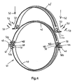
- Fig. 4 shows a different pipe clip 41 with a metal clip body comprising two clip halves 42 and 43 respectively.
- the first clip half 42 is provided at both ends with a flange 44 and 45 respectively.
- the second clip half 43 is provided at both ends with a flange 46 and 47 respectively.
- the flange 44 of the first clip half 42 opposes the flange 46 of the second clip half 43
- the flange 45 of the first clip half 42 opposes the flange 47 of the second clip half 43.
- the second clip half 43 has in each of the flanges 46 and 47 a screw hole into which a tightening screw 50 and 51 respectively is screwed.
- the first clip half 43 has in the flanges 44 and 45 respectively a recess 48 and 49 respectively for the shank of the respective tightening screws 50 and 51.
- the first clip half 42 is also represented in a non-connected state and denoted by reference numeral 42'.
- the arrows 52 illustrate the direction of movement when the first clip half 42 is placed on the second clip half 43 and around a pipe (not shown).
- the flanges 44 and 45 of the clip half 42 are placed against the head 50a, 51 a of the tightening screws 50, 51.
- the exertion of further pressure causes the clip half 42 to become deformed, the flanges 44 and 45 being moved outward, as is illustrated by arrows 53.
- the flange 44 is shown in broken lines in various positions during the outward movement.
- the head 50a and 51a respectively can be inserted through the opening 401 and 402 respectively, after which the clip half 42 can recoil, wherein the shank 50b and 51 b respectively of the tightening screw 50 and 51 respectively can be received in the elongate opening 48 and 49 respectively.
- the clip halves 42 and 43 are then connected to each other by means of this quick-acting closure. Subsequently, the tightening screws 50 and 51 can then be tightened in order to tighten the clip halves 42 and 43 around the pipe.
- the pipe clip 41 shown in Fig. 4 has the advantage that the clip halves 42, 43 can be packaged loose and, for example, nested one within the other, so less free space is necessary in the packaging. However, the fitter does not have to screw the pipe clip halves 42, 43 together prior to use. This is particularly advantageous in the case of pipe clips for pipes having relatively large diameters.
- the pipe clip comprises two identical clip halves. Each clip half then has on one side a flange comparable to the flange 46, 47 and on the other side a flange comparable to the flange 44, 45. In this way, merely one type of clip half has to be manufactured, and this is beneficial in the light of production costs. After manufacture, one of the clip halves can be provided with a nut, a screw hole or the like in order to be able to suspend the pipe clip from a threaded end or the like.
Landscapes
- Engineering & Computer Science (AREA)
- General Engineering & Computer Science (AREA)
- Mechanical Engineering (AREA)
- Clamps And Clips (AREA)
- Supports For Pipes And Cables (AREA)
Priority Applications (1)
| Application Number | Priority Date | Filing Date | Title |
|---|---|---|---|
| PL07076041T PL1939507T3 (pl) | 2006-12-27 | 2007-12-04 | Zacisk do rury |
Applications Claiming Priority (1)
| Application Number | Priority Date | Filing Date | Title |
|---|---|---|---|
| NL1033138A NL1033138C2 (nl) | 2006-12-27 | 2006-12-27 | Pijpbeugel. |
Publications (2)
| Publication Number | Publication Date |
|---|---|
| EP1939507A1 true EP1939507A1 (fr) | 2008-07-02 |
| EP1939507B1 EP1939507B1 (fr) | 2018-10-24 |
Family
ID=38293702
Family Applications (1)
| Application Number | Title | Priority Date | Filing Date |
|---|---|---|---|
| EP07076041.8A Active EP1939507B1 (fr) | 2006-12-27 | 2007-12-04 | Collier de serrage |
Country Status (5)
| Country | Link |
|---|---|
| US (1) | US8047476B2 (fr) |
| EP (1) | EP1939507B1 (fr) |
| ES (1) | ES2700464T3 (fr) |
| NL (1) | NL1033138C2 (fr) |
| PL (1) | PL1939507T3 (fr) |
Cited By (2)
| Publication number | Priority date | Publication date | Assignee | Title |
|---|---|---|---|---|
| CN103322320A (zh) * | 2013-07-08 | 2013-09-25 | 上海铭东建筑工程有限公司 | 一种带垫片卡箍 |
| USD950369S1 (en) | 2017-05-22 | 2022-05-03 | Erico International Corporation | Pipe clamp |
Families Citing this family (18)
| Publication number | Priority date | Publication date | Assignee | Title |
|---|---|---|---|---|
| KR101248660B1 (ko) * | 2009-04-23 | 2013-03-28 | 카야바 고교 가부시기가이샤 | 실린더 튜브의 배관 고정 구조 |
| US20120325578A1 (en) * | 2011-06-21 | 2012-12-27 | E I Du Pont De Nemours And Company | Muffler assembly and method of making |
| US20130328305A1 (en) * | 2012-06-12 | 2013-12-12 | Avi Chiproot | Seal holding device for pipe clamp |
| US9322492B2 (en) * | 2012-08-23 | 2016-04-26 | Westinghouse Electric Company Llc | Pipeline clamp for vibration measurement |
| US9347587B2 (en) | 2012-09-05 | 2016-05-24 | James John Allivato, SR. | Duct mounting system and kit |
| US9190741B2 (en) | 2013-03-12 | 2015-11-17 | Thomas & Betts International Llc | Hybrid grounding connector |
| US9673537B2 (en) | 2013-03-15 | 2017-06-06 | Thomas & Betts International, Llc | Wire compression connector |
| US8857084B2 (en) | 2013-05-20 | 2014-10-14 | Gary Courter | Mobile advertising displays |
| US10344538B2 (en) * | 2016-01-12 | 2019-07-09 | Austin Engineering Usa Services, Inc. | Support clamp |
| CA3019553A1 (fr) * | 2016-03-30 | 2017-10-05 | Hydra-Zorb | Fixation de colonne montante isolee |
| NL2017895B1 (en) * | 2016-11-30 | 2018-06-11 | Walraven Holding Bv J Van | Vibration isolating insert for a pipe clip |
| PT3410033T (pt) * | 2017-05-31 | 2020-03-23 | Soltec Energias Renovables Sl | Dispositivo de suporte para um veio rotativo de um rastreador solar |
| KR102067268B1 (ko) | 2018-01-30 | 2020-01-16 | 효성중공업 주식회사 | 변압기용 배관지지장치 |
| WO2019232581A1 (fr) * | 2018-06-06 | 2019-12-12 | Abey Australia Pty. Ltd. | Extrusions d'amortissement |
| DE102019202306B4 (de) * | 2019-02-20 | 2024-07-04 | Thyssenkrupp Ag | Stabilisatorschelle, Stabilisator-Stabilisatorschellen-Anordnung und Verfahren zum Herstellen einer Stabilisatorschelle |
| USD1035432S1 (en) * | 2021-11-12 | 2024-07-16 | Rmh Tech Llc | Pipe clamp with a threaded extension |
| TWI833371B (zh) * | 2022-09-28 | 2024-02-21 | 啟碁科技股份有限公司 | 懸吊支架及其安裝方法 |
| WO2025014876A1 (fr) * | 2023-07-10 | 2025-01-16 | Victaulic Company | Support de verrouillage |
Citations (7)
| Publication number | Priority date | Publication date | Assignee | Title |
|---|---|---|---|---|
| DE3308459A1 (de) * | 1983-03-10 | 1984-09-13 | Peter Dipl.-Ing. 8500 Nürnberg Wölfel | Rohrschelle |
| DE8503846U1 (de) * | 1985-02-13 | 1985-05-09 | Lenk, Heinz-Rüdiger, 5983 Balve | Rohrschelle |
| FR2571465A1 (fr) * | 1984-10-06 | 1986-04-11 | Mueller Franz | Collier pour tuyaux |
| EP0225516A2 (fr) * | 1985-12-07 | 1987-06-16 | Franz Müller | Collier de serrage |
| DE4015404A1 (de) | 1990-03-26 | 1991-12-19 | Maechtle Woehler Margot | Rohrschelle |
| EP0597193A2 (fr) | 1992-08-11 | 1994-05-18 | Mächtle-Wöhler, Margot | Collier de fixation |
| DE10003183A1 (de) * | 2000-01-25 | 2001-08-02 | Wolfgang Halpaus | Rohrschelle |
Family Cites Families (4)
| Publication number | Priority date | Publication date | Assignee | Title |
|---|---|---|---|---|
| US1063852A (en) * | 1912-04-26 | 1913-06-03 | Lewis A Carpenter | Pipe-hanger. |
| US2397279A (en) * | 1944-05-23 | 1946-03-26 | Adel Prec Products Corp | Snap lock harness clip |
| USD489000S1 (en) * | 2001-10-01 | 2004-04-27 | Warwick Hanger Co. | Bell type pipe hanger |
| JP2006275076A (ja) * | 2005-03-28 | 2006-10-12 | Akagi:Kk | 配管用吊りバンド |
-
2006
- 2006-12-27 NL NL1033138A patent/NL1033138C2/nl not_active IP Right Cessation
-
2007
- 2007-12-04 ES ES07076041T patent/ES2700464T3/es active Active
- 2007-12-04 PL PL07076041T patent/PL1939507T3/pl unknown
- 2007-12-04 EP EP07076041.8A patent/EP1939507B1/fr active Active
- 2007-12-27 US US11/965,376 patent/US8047476B2/en active Active
Patent Citations (7)
| Publication number | Priority date | Publication date | Assignee | Title |
|---|---|---|---|---|
| DE3308459A1 (de) * | 1983-03-10 | 1984-09-13 | Peter Dipl.-Ing. 8500 Nürnberg Wölfel | Rohrschelle |
| FR2571465A1 (fr) * | 1984-10-06 | 1986-04-11 | Mueller Franz | Collier pour tuyaux |
| DE8503846U1 (de) * | 1985-02-13 | 1985-05-09 | Lenk, Heinz-Rüdiger, 5983 Balve | Rohrschelle |
| EP0225516A2 (fr) * | 1985-12-07 | 1987-06-16 | Franz Müller | Collier de serrage |
| DE4015404A1 (de) | 1990-03-26 | 1991-12-19 | Maechtle Woehler Margot | Rohrschelle |
| EP0597193A2 (fr) | 1992-08-11 | 1994-05-18 | Mächtle-Wöhler, Margot | Collier de fixation |
| DE10003183A1 (de) * | 2000-01-25 | 2001-08-02 | Wolfgang Halpaus | Rohrschelle |
Cited By (2)
| Publication number | Priority date | Publication date | Assignee | Title |
|---|---|---|---|---|
| CN103322320A (zh) * | 2013-07-08 | 2013-09-25 | 上海铭东建筑工程有限公司 | 一种带垫片卡箍 |
| USD950369S1 (en) | 2017-05-22 | 2022-05-03 | Erico International Corporation | Pipe clamp |
Also Published As
| Publication number | Publication date |
|---|---|
| US8047476B2 (en) | 2011-11-01 |
| EP1939507B1 (fr) | 2018-10-24 |
| NL1033138C2 (nl) | 2008-06-30 |
| PL1939507T3 (pl) | 2019-05-31 |
| ES2700464T3 (es) | 2019-02-15 |
| US20090026766A1 (en) | 2009-01-29 |
Similar Documents
| Publication | Publication Date | Title |
|---|---|---|
| EP1939507B1 (fr) | Collier de serrage | |
| EP1933072B1 (fr) | Collier de serrage | |
| US7490388B2 (en) | Pipe clamp with spring nut | |
| EP3022475B1 (fr) | Attache de tuyau avec fonctionnalité de blocage | |
| EP1978288B1 (fr) | Fixation de tuyau à fermeture rapide | |
| EP2707633B1 (fr) | Collier de fixation | |
| EP2492563A1 (fr) | Pince pour tuyau ou câble | |
| EP3543575B1 (fr) | Ensemble de serrage et procédé de serrage | |
| AU2018391659B2 (en) | Load carrier foot | |
| KR20130069360A (ko) | 프로파일링된 클램프 | |
| US8161605B2 (en) | Hose clamp | |
| US20060101576A1 (en) | Faucet quick install nut | |
| US5669589A (en) | Pipe and cable clamp with base part and receiving strap | |
| CZ252998A3 (cs) | Trubní objímka | |
| JP2015511301A (ja) | 管継手 | |
| EP2156083B1 (fr) | Bride pour la suspension d'un conduit | |
| NL2008229C2 (en) | Pipe clip. | |
| JP6453948B1 (ja) | パイプ接続具 | |
| EP1771676B1 (fr) | Bride de serrage pour tuyau souple | |
| DK176131B1 (da) | Beslag, især til fastholdelse af delvis eftergivelige eller deformerbare emner til en konsol | |
| JP2006329358A (ja) | ボルトの連結金具。 |
Legal Events
| Date | Code | Title | Description |
|---|---|---|---|
| PUAI | Public reference made under article 153(3) epc to a published international application that has entered the european phase |
Free format text: ORIGINAL CODE: 0009012 |
|
| AK | Designated contracting states |
Kind code of ref document: A1 Designated state(s): AT BE BG CH CY CZ DE DK EE ES FI FR GB GR HU IE IS IT LI LT LU LV MC MT NL PL PT RO SE SI SK TR |
|
| AX | Request for extension of the european patent |
Extension state: AL BA HR MK RS |
|
| 17P | Request for examination filed |
Effective date: 20080808 |
|
| AKX | Designation fees paid |
Designated state(s): AT BE BG CH CY CZ DE DK EE ES FI FR GB GR HU IE IS IT LI LT LU LV MC MT NL PL PT RO SE SI SK TR |
|
| 17Q | First examination report despatched |
Effective date: 20100426 |
|
| GRAP | Despatch of communication of intention to grant a patent |
Free format text: ORIGINAL CODE: EPIDOSNIGR1 |
|
| INTG | Intention to grant announced |
Effective date: 20180613 |
|
| GRAS | Grant fee paid |
Free format text: ORIGINAL CODE: EPIDOSNIGR3 |
|
| GRAA | (expected) grant |
Free format text: ORIGINAL CODE: 0009210 |
|
| AK | Designated contracting states |
Kind code of ref document: B1 Designated state(s): AT BE BG CH CY CZ DE DK EE ES FI FR GB GR HU IE IS IT LI LT LU LV MC MT NL PL PT RO SE SI SK TR |
|
| REG | Reference to a national code |
Ref country code: GB Ref legal event code: FG4D |
|
| REG | Reference to a national code |
Ref country code: CH Ref legal event code: EP |
|
| REG | Reference to a national code |
Ref country code: IE Ref legal event code: FG4D |
|
| REG | Reference to a national code |
Ref country code: AT Ref legal event code: REF Ref document number: 1057075 Country of ref document: AT Kind code of ref document: T Effective date: 20181115 |
|
| REG | Reference to a national code |
Ref country code: DE Ref legal event code: R096 Ref document number: 602007056570 Country of ref document: DE |
|
| REG | Reference to a national code |
Ref country code: NL Ref legal event code: FP |
|
| REG | Reference to a national code |
Ref country code: ES Ref legal event code: FG2A Ref document number: 2700464 Country of ref document: ES Kind code of ref document: T3 Effective date: 20190215 |
|
| REG | Reference to a national code |
Ref country code: LT Ref legal event code: MG4D |
|
| REG | Reference to a national code |
Ref country code: AT Ref legal event code: MK05 Ref document number: 1057075 Country of ref document: AT Kind code of ref document: T Effective date: 20181024 |
|
| PG25 | Lapsed in a contracting state [announced via postgrant information from national office to epo] |
Ref country code: IS Free format text: LAPSE BECAUSE OF FAILURE TO SUBMIT A TRANSLATION OF THE DESCRIPTION OR TO PAY THE FEE WITHIN THE PRESCRIBED TIME-LIMIT Effective date: 20190224 Ref country code: AT Free format text: LAPSE BECAUSE OF FAILURE TO SUBMIT A TRANSLATION OF THE DESCRIPTION OR TO PAY THE FEE WITHIN THE PRESCRIBED TIME-LIMIT Effective date: 20181024 Ref country code: LT Free format text: LAPSE BECAUSE OF FAILURE TO SUBMIT A TRANSLATION OF THE DESCRIPTION OR TO PAY THE FEE WITHIN THE PRESCRIBED TIME-LIMIT Effective date: 20181024 Ref country code: BG Free format text: LAPSE BECAUSE OF FAILURE TO SUBMIT A TRANSLATION OF THE DESCRIPTION OR TO PAY THE FEE WITHIN THE PRESCRIBED TIME-LIMIT Effective date: 20190124 Ref country code: FI Free format text: LAPSE BECAUSE OF FAILURE TO SUBMIT A TRANSLATION OF THE DESCRIPTION OR TO PAY THE FEE WITHIN THE PRESCRIBED TIME-LIMIT Effective date: 20181024 Ref country code: LV Free format text: LAPSE BECAUSE OF FAILURE TO SUBMIT A TRANSLATION OF THE DESCRIPTION OR TO PAY THE FEE WITHIN THE PRESCRIBED TIME-LIMIT Effective date: 20181024 |
|
| PG25 | Lapsed in a contracting state [announced via postgrant information from national office to epo] |
Ref country code: SE Free format text: LAPSE BECAUSE OF FAILURE TO SUBMIT A TRANSLATION OF THE DESCRIPTION OR TO PAY THE FEE WITHIN THE PRESCRIBED TIME-LIMIT Effective date: 20181024 Ref country code: PT Free format text: LAPSE BECAUSE OF FAILURE TO SUBMIT A TRANSLATION OF THE DESCRIPTION OR TO PAY THE FEE WITHIN THE PRESCRIBED TIME-LIMIT Effective date: 20190224 Ref country code: GR Free format text: LAPSE BECAUSE OF FAILURE TO SUBMIT A TRANSLATION OF THE DESCRIPTION OR TO PAY THE FEE WITHIN THE PRESCRIBED TIME-LIMIT Effective date: 20190125 |
|
| REG | Reference to a national code |
Ref country code: DE Ref legal event code: R097 Ref document number: 602007056570 Country of ref document: DE |
|
| PG25 | Lapsed in a contracting state [announced via postgrant information from national office to epo] |
Ref country code: DK Free format text: LAPSE BECAUSE OF FAILURE TO SUBMIT A TRANSLATION OF THE DESCRIPTION OR TO PAY THE FEE WITHIN THE PRESCRIBED TIME-LIMIT Effective date: 20181024 |
|
| REG | Reference to a national code |
Ref country code: CH Ref legal event code: PL |
|
| PG25 | Lapsed in a contracting state [announced via postgrant information from national office to epo] |
Ref country code: LU Free format text: LAPSE BECAUSE OF NON-PAYMENT OF DUE FEES Effective date: 20181204 Ref country code: RO Free format text: LAPSE BECAUSE OF FAILURE TO SUBMIT A TRANSLATION OF THE DESCRIPTION OR TO PAY THE FEE WITHIN THE PRESCRIBED TIME-LIMIT Effective date: 20181024 Ref country code: EE Free format text: LAPSE BECAUSE OF FAILURE TO SUBMIT A TRANSLATION OF THE DESCRIPTION OR TO PAY THE FEE WITHIN THE PRESCRIBED TIME-LIMIT Effective date: 20181024 Ref country code: MC Free format text: LAPSE BECAUSE OF FAILURE TO SUBMIT A TRANSLATION OF THE DESCRIPTION OR TO PAY THE FEE WITHIN THE PRESCRIBED TIME-LIMIT Effective date: 20181024 Ref country code: SK Free format text: LAPSE BECAUSE OF FAILURE TO SUBMIT A TRANSLATION OF THE DESCRIPTION OR TO PAY THE FEE WITHIN THE PRESCRIBED TIME-LIMIT Effective date: 20181024 |
|
| PLBE | No opposition filed within time limit |
Free format text: ORIGINAL CODE: 0009261 |
|
| STAA | Information on the status of an ep patent application or granted ep patent |
Free format text: STATUS: NO OPPOSITION FILED WITHIN TIME LIMIT |
|
| REG | Reference to a national code |
Ref country code: IE Ref legal event code: MM4A |
|
| 26N | No opposition filed |
Effective date: 20190725 |
|
| REG | Reference to a national code |
Ref country code: BE Ref legal event code: MM Effective date: 20181231 |
|
| PG25 | Lapsed in a contracting state [announced via postgrant information from national office to epo] |
Ref country code: IE Free format text: LAPSE BECAUSE OF NON-PAYMENT OF DUE FEES Effective date: 20181204 Ref country code: SI Free format text: LAPSE BECAUSE OF FAILURE TO SUBMIT A TRANSLATION OF THE DESCRIPTION OR TO PAY THE FEE WITHIN THE PRESCRIBED TIME-LIMIT Effective date: 20181024 |
|
| PG25 | Lapsed in a contracting state [announced via postgrant information from national office to epo] |
Ref country code: BE Free format text: LAPSE BECAUSE OF NON-PAYMENT OF DUE FEES Effective date: 20181231 |
|
| PG25 | Lapsed in a contracting state [announced via postgrant information from national office to epo] |
Ref country code: CH Free format text: LAPSE BECAUSE OF NON-PAYMENT OF DUE FEES Effective date: 20181231 Ref country code: LI Free format text: LAPSE BECAUSE OF NON-PAYMENT OF DUE FEES Effective date: 20181231 |
|
| PG25 | Lapsed in a contracting state [announced via postgrant information from national office to epo] |
Ref country code: MT Free format text: LAPSE BECAUSE OF NON-PAYMENT OF DUE FEES Effective date: 20181204 |
|
| PG25 | Lapsed in a contracting state [announced via postgrant information from national office to epo] |
Ref country code: TR Free format text: LAPSE BECAUSE OF FAILURE TO SUBMIT A TRANSLATION OF THE DESCRIPTION OR TO PAY THE FEE WITHIN THE PRESCRIBED TIME-LIMIT Effective date: 20181024 |
|
| PG25 | Lapsed in a contracting state [announced via postgrant information from national office to epo] |
Ref country code: HU Free format text: LAPSE BECAUSE OF FAILURE TO SUBMIT A TRANSLATION OF THE DESCRIPTION OR TO PAY THE FEE WITHIN THE PRESCRIBED TIME-LIMIT; INVALID AB INITIO Effective date: 20071204 Ref country code: CY Free format text: LAPSE BECAUSE OF FAILURE TO SUBMIT A TRANSLATION OF THE DESCRIPTION OR TO PAY THE FEE WITHIN THE PRESCRIBED TIME-LIMIT Effective date: 20181024 |
|
| PGFP | Annual fee paid to national office [announced via postgrant information from national office to epo] |
Ref country code: GB Payment date: 20251218 Year of fee payment: 19 |
|
| PGFP | Annual fee paid to national office [announced via postgrant information from national office to epo] |
Ref country code: NL Payment date: 20251223 Year of fee payment: 19 Ref country code: FR Payment date: 20251218 Year of fee payment: 19 |
|
| PGFP | Annual fee paid to national office [announced via postgrant information from national office to epo] |
Ref country code: CZ Payment date: 20251124 Year of fee payment: 19 |
|
| PGFP | Annual fee paid to national office [announced via postgrant information from national office to epo] |
Ref country code: PL Payment date: 20251121 Year of fee payment: 19 |
|
| PGFP | Annual fee paid to national office [announced via postgrant information from national office to epo] |
Ref country code: ES Payment date: 20260119 Year of fee payment: 19 |
|
| PGFP | Annual fee paid to national office [announced via postgrant information from national office to epo] |
Ref country code: DE Payment date: 20251222 Year of fee payment: 19 |
|
| PGFP | Annual fee paid to national office [announced via postgrant information from national office to epo] |
Ref country code: IT Payment date: 20251231 Year of fee payment: 19 |