EP1939571A2 - Wärmetauschelement für eine Belüftungsvorrichtung - Google Patents
Wärmetauschelement für eine Belüftungsvorrichtung Download PDFInfo
- Publication number
- EP1939571A2 EP1939571A2 EP07116977A EP07116977A EP1939571A2 EP 1939571 A2 EP1939571 A2 EP 1939571A2 EP 07116977 A EP07116977 A EP 07116977A EP 07116977 A EP07116977 A EP 07116977A EP 1939571 A2 EP1939571 A2 EP 1939571A2
- Authority
- EP
- European Patent Office
- Prior art keywords
- heat exchange
- heat exchanger
- aperture
- guide
- guide rib
- Prior art date
- Legal status (The legal status is an assumption and is not a legal conclusion. Google has not performed a legal analysis and makes no representation as to the accuracy of the status listed.)
- Withdrawn
Links
Images







Classifications
-
- F—MECHANICAL ENGINEERING; LIGHTING; HEATING; WEAPONS; BLASTING
- F28—HEAT EXCHANGE IN GENERAL
- F28D—HEAT-EXCHANGE APPARATUS, NOT PROVIDED FOR IN ANOTHER SUBCLASS, IN WHICH THE HEAT-EXCHANGE MEDIA DO NOT COME INTO DIRECT CONTACT
- F28D21/00—Heat-exchange apparatus not covered by any of the groups F28D1/00 - F28D20/00
- F28D21/0015—Heat and mass exchangers, e.g. with permeable walls
-
- F—MECHANICAL ENGINEERING; LIGHTING; HEATING; WEAPONS; BLASTING
- F24—HEATING; RANGES; VENTILATING
- F24F—AIR-CONDITIONING; AIR-HUMIDIFICATION; VENTILATION; USE OF AIR CURRENTS FOR SCREENING
- F24F7/00—Ventilation
- F24F7/04—Ventilation with ducting systems, e.g. by double walls; with natural circulation
- F24F7/06—Ventilation with ducting systems, e.g. by double walls; with natural circulation with forced air circulation, e.g. by fan positioning of a ventilator in or against a conduit
- F24F7/08—Ventilation with ducting systems, e.g. by double walls; with natural circulation with forced air circulation, e.g. by fan positioning of a ventilator in or against a conduit with separate ducts for supplied and exhausted air with provisions for reversal of the input and output systems
-
- F—MECHANICAL ENGINEERING; LIGHTING; HEATING; WEAPONS; BLASTING
- F24—HEATING; RANGES; VENTILATING
- F24F—AIR-CONDITIONING; AIR-HUMIDIFICATION; VENTILATION; USE OF AIR CURRENTS FOR SCREENING
- F24F12/00—Use of energy recovery systems in air conditioning, ventilation or screening
- F24F12/001—Use of energy recovery systems in air conditioning, ventilation or screening with heat-exchange between supplied and exhausted air
- F24F12/006—Use of energy recovery systems in air conditioning, ventilation or screening with heat-exchange between supplied and exhausted air using an air-to-air heat exchanger
-
- F—MECHANICAL ENGINEERING; LIGHTING; HEATING; WEAPONS; BLASTING
- F28—HEAT EXCHANGE IN GENERAL
- F28D—HEAT-EXCHANGE APPARATUS, NOT PROVIDED FOR IN ANOTHER SUBCLASS, IN WHICH THE HEAT-EXCHANGE MEDIA DO NOT COME INTO DIRECT CONTACT
- F28D9/00—Heat-exchange apparatus having stationary plate-like or laminated conduit assemblies for both heat-exchange media, the media being in contact with different sides of a conduit wall
- F28D9/0062—Heat-exchange apparatus having stationary plate-like or laminated conduit assemblies for both heat-exchange media, the media being in contact with different sides of a conduit wall the conduits for one heat-exchange medium being formed by spaced plates with inserted elements
- F28D9/0068—Heat-exchange apparatus having stationary plate-like or laminated conduit assemblies for both heat-exchange media, the media being in contact with different sides of a conduit wall the conduits for one heat-exchange medium being formed by spaced plates with inserted elements with means for changing flow direction of one heat exchange medium, e.g. using deflecting zones
-
- F—MECHANICAL ENGINEERING; LIGHTING; HEATING; WEAPONS; BLASTING
- F28—HEAT EXCHANGE IN GENERAL
- F28F—DETAILS OF HEAT-EXCHANGE AND HEAT-TRANSFER APPARATUS, OF GENERAL APPLICATION
- F28F13/00—Arrangements for modifying heat-transfer, e.g. increasing, decreasing
- F28F13/06—Arrangements for modifying heat-transfer, e.g. increasing, decreasing by affecting the pattern of flow of the heat-exchange media
-
- F—MECHANICAL ENGINEERING; LIGHTING; HEATING; WEAPONS; BLASTING
- F28—HEAT EXCHANGE IN GENERAL
- F28F—DETAILS OF HEAT-EXCHANGE AND HEAT-TRANSFER APPARATUS, OF GENERAL APPLICATION
- F28F2250/00—Arrangements for modifying the flow of the heat exchange media, e.g. flow guiding means; Particular flow patterns
- F28F2250/04—Communication passages between channels
-
- F—MECHANICAL ENGINEERING; LIGHTING; HEATING; WEAPONS; BLASTING
- F28—HEAT EXCHANGE IN GENERAL
- F28F—DETAILS OF HEAT-EXCHANGE AND HEAT-TRANSFER APPARATUS, OF GENERAL APPLICATION
- F28F2250/00—Arrangements for modifying the flow of the heat exchange media, e.g. flow guiding means; Particular flow patterns
- F28F2250/10—Particular pattern of flow of the heat exchange media
- F28F2250/108—Particular pattern of flow of the heat exchange media with combined cross flow and parallel flow
-
- Y—GENERAL TAGGING OF NEW TECHNOLOGICAL DEVELOPMENTS; GENERAL TAGGING OF CROSS-SECTIONAL TECHNOLOGIES SPANNING OVER SEVERAL SECTIONS OF THE IPC; TECHNICAL SUBJECTS COVERED BY FORMER USPC CROSS-REFERENCE ART COLLECTIONS [XRACs] AND DIGESTS
- Y02—TECHNOLOGIES OR APPLICATIONS FOR MITIGATION OR ADAPTATION AGAINST CLIMATE CHANGE
- Y02B—CLIMATE CHANGE MITIGATION TECHNOLOGIES RELATED TO BUILDINGS, e.g. HOUSING, HOUSE APPLIANCES OR RELATED END-USER APPLICATIONS
- Y02B30/00—Energy efficient heating, ventilation or air conditioning [HVAC]
- Y02B30/56—Heat recovery units
Definitions
- the present disclosure relates to a heat exchanger used in a ventilating apparatus.
- the present application discloses heat exchange plates which can be stacked to form a heat exchanger.
- a ventilating apparatus can be used for ventilating an enclosed space.
- the ventilating apparatus is designed to perform a heat exchange operation in which heat is exchanged between incoming outdoor air and outgoing indoor air before the outdoor air is introduced to the enclosed space.
- the ventilating apparatus is a kind of air conditioning apparatuses that ventilates the room such that indoor temperature does not decrease or increase abruptly, even though outdoor air is introduced during the ventilation process.
- the ventilating apparatus is configured with a plurality of ducts which can be arranged to cross one another or which can be arranged in parallel.
- the outdoor air and the indoor air flow in opposite directions through adjacent ducts to accomplish the heat exchange operation.
- An important performance factor in this type of ventilating apparatus is to maintain the temperature and humidity of air within the enclosed space. This is accomplished by conducting a heat and moisture exchange operation so that the temperature and humidity of air being sent into the enclosed space is almost equal to that of air being removed from the space.
- the ducts of the heat exchanger must have maximum heat transfer efficiency and moisture permeability. It also helps to form the ducts so that they are as fine and compact as possible for contacting air over the broadest surface area.
- the heat exchanger In addition to the above, it is desirable to have the heat exchanger produce minimum noise and minimum power consumption in introducing fresh outdoor air and exhausting indoor air for ventilation. For the minimum noise and power consumption, the conduit resistance of an internal heat exchange duct must be low. Unfortunately, as the heat exchanger is configured for maximum heat and moisture exchange, noise and power consumption go up.
- a related art heat exchange duct is provided with heat exchange "sheets," and ribs between the sheets help to maintain the multi-stacked arrangement of the heat exchange sheets. Main heat exchange is performed by heat transfer through the sheets. Likewise, moisture exchange is accomplished by moisture permeation between the sheets.
- the heat exchange sheets may be made of thin paper, and thus the heat exchange sheets may sag if they absorb moisture.
- the ribs which help to support the sheets, are attached to the heat exchange sheets in molten resin form and are then cured.
- the ribs between the sheets form ducts with the heat exchange sheets and the air flows through these ducts.
- Different gases (these gases would typically be the outdoor air and the indoor air) flow on opposite sides of each sheet in such a way that they cross each other, or flow in opposite directions
- pressure or flow velocity is not uniform in each duct, or even at different locations within the same duct. These localized flow differentials can degrade performance.
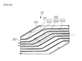
- FIGs. 4A and 4B are exploded perspective views illustrating the constitution of a background art heat exchange element.
- an intake heat exchange element 21 and an exhaust heat exchange element 22, which have hexagonal shapes, are alternately stacked.
- Intake passages and the exhaust passages are formed between the intake heat exchange elements 21 and the exhaust heat exchange elements 22.
- the intake heat exchange element 21 includes a heat exchange sheet 211 made of thin paper material. Guide ribs 212 are disposed on one side of a heat exchange sheet 211 such that they are spaced apart by predetermined distances. A frame 213 is provided on edge portions of the heat exchange sheet 211 to maintain the shape of the intake heat exchange element 21.
- the guide rib 212 is divided into three sections, i.e., an outdoor air intake section 212a, an intermediate section 212b and an outdoor air exhaust section 212c.
- the outdoor air intake section 212a and the outdoor air exhaust section 212c are disposed at opposite ends of the intermediate section 212c.
- the introduction guide rib 212 is formed such that the outdoor air intake section 212a and the outdoor air exhaust section 212b extend at a predetermined angle with respect to the intermediate section 212b.
- the exhaust heat exchange element 22 includes a heat exchange sheet 221, and exhaust guide ribs 222 attached to one side of the heat exchange sheet 221.
- a frame 223 surrounds the heat exchanger sheet 221.
- the exhaust guide ribs 222 are also configured with an intake portion 222a, a straight intermediate portion 222b and an exhaust portion 222c.
- the intermediate portions 221b and 222b of the intake and exhaust sheets are parallel to one another. However, the intake portions 222a and the exhaust portions 222c of the exhaust guide ribs 222 cross the intake portion 212a and the exhaust portion 212c of the introduction guide rib 212.
- reference symbol P ⁇ denotes a section where air velocity decreases, but pressure temporarily increases. This is undesirable, and it typically occurs at bent portions of the ribs where the air flow must change direction. The increased pressure results in lowering the flow velocity. This is called a pressure loss.
- the pressure loss caused by such a local pressure increase is dependent upon a turning angle and a length of a bent portion of the duct. For example, referring to Fig. 4B , residual pressures P 1 and P 2 of air in adjacent ducts at exhaust ends are different from each other.
- Fig. 1 is a perspective view illustrating an internal structure of a ventilating apparatus
- Fig. 2 is a sectional view illustrating introduction/exhaust of outdoor air in the ventilating apparatus of Fig. 1 ;
- Fig. 3 is a sectional view illustrating introduction/exhaust of indoor air in the ventilating apparatus of Fig. 1 ;
- Figs. 4A and 4B are perspective views illustrating the constitution of a related art heat exchange element.
- Fig. 5 is a plan view of an embodiment of a heat exchange plate redressing disadvantages of the related art heat exchange plate of Figs. 4A and 4B .
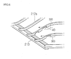
- Fig. 6 is an enlarged view of a portion of an embodiment of a heat exchange element corresponding to part A of Fig. 4B ;
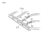
- Fig. 7 is an enlarged view of a portion of an embodiment of a heat exchange element corresponding to part A of Fig. 4B ;
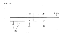
- Figs. 8 , and 9A to 9C are views illustrating modified shapes and arrangments of ribs of various embodiments of heat exchange elements.
- Fig. 1 is a perspective view illustrating an internal structure of a ventilating apparatus 10.
- the ventilating apparatus 10 includes a case 11 forming an external shape, and a heat exchanger 20.
- an intake fan 16 is configured to introduce outdoor air into a room.
- an exhaust fan 17 is configured to blow indoor air to the outside.
- the heat exchanger 20 conducts a heat and moisture exchange operation between incoming outdoor air and outgoing indoor.
- An intake air inlet 12 introduces outdoor air and an exhaust air outlet 15 exhausts indoor air to the outside.
- an intake air outlet 13 discharges the introduced outdoor air to the indoor space, and an exhaust air inlet 14 introduces the indoor air into the ventilating unit.
- An intake passage is provided between the intake air inlet 12 and the intake air outlet 13.
- the heat exchanger 20 intervenes in the middle of the intake passage.
- An exhaust passage is also provided between the exhaust air inlet 14 and the exhaust air outlet 15.
- the heat exchanger 20 also intervenes in the middle of the exhaust passage. The outdoor air introduced through the intake air inlet 12 and the indoor air introduced through the exhaust air inlet 14 exchange heat and moisture with each other, without being mixed, while passing through the heat exchanger 20.
- Fig. 2 is a sectional view illustrating the introduction/exhaust of outdoor air in the ventilating apparatus 10 of Fig.1 .
- Fig. 3 is a sectional view illustrating the introduction/exhaust of indoor air in the ventilating apparatus 10 of Fig. 1 .
- the intake fan 16 is mounted inside the duct at a side of the intake air outlet 13 to introduce the outdoor air.
- the outdoor air is introduced through the intake air inlet 12 by the operation of the intake fan 16, and is then heat exchanged with the indoor air while passing through the heat exchanger 20.
- the exhaust fan 17 is mounted inside the duct at a side of the exhaust air outlet 15 to introduce the indoor air.
- the indoor air is introduced through the exhaust inlet 14 by the operation of the exhaust fan 17, and the indoor air is then heat exchanged with the outdoor air while passing through the heat exchanger 20.
- the heat exchanger 20 includes a plurality of stacked heat exchange plates.
- the heat exchange plates are configured such that guide ribs are disposed between heat exchange sheets.
- the stacked structure of the heat exchange sheets and the guide ribs form ducts which guide the introduced indoor air and outdoor air.
- the ducts through which the indoor air flows and the ducts through which the outdoor air flows are cross-arranged at left and right sides of the heat exchanger, respectively. Therefore, the outdoor air and the indoor air can exchange heat and moisture with each other, without being mixed, while they pass through the heat exchanger 20.
- Figs. 5-9c illustrate various embodiments of heat exchange plates that redressing disadvantages of the related are heat exchange plates shown in Figs. 4A and 4B .
- the heat exchange elements are designed to solve flow rate non-uniformity caused by pressure non-uniformity at air intake and exhaust ends.
- the heat exchanger is shaped like a quadratic prism or a hexagonal prism.
- the heat exchanger has a structure in which a plurality of heat exchange sheets stacked.
- ribs would only be formed on one side of each heat exchange sheet. In other embodiments, ribs are disposed on both sides of each heat exchange sheet.
- each heat exchange plate would include a heat exchange sheet, a plurality of first ribs arranged on one surface of the heat exchange sheet and guiding a first gas flowing along the first surface of the heat exchange sheet, and a plurality of second ribs arranged on the opposite surface of the heat exchange sheet. The second ribs would guide a second gas flowing along the opposite surface of the heat exchange sheet.
- the heat exchange plate 1 includes a heat exchange sheet 3, a frame 2 surrounding the heat exchange sheet 3, an introduction guide rib 4 disposed on one side of the heat exchange sheet 3, and an exhaust guide rib 5 disposed on the other side of the heat exchange sheet 3.
- Some of the guide ribs are intermittently arranged at intake and exhaust ends of the intake and exhaust guide ribs 4 and 5, as illustrated in Fig. 5 . That is, the guide ribs are spaced apart at regular intervals so that the introduced or exhausted air flows dispersedly.
- intake air is introduced along a plurality of ducts, and exhausted along a plurality of ducts, which makes it possible to reduce pressure loss at air intake and exhaust ends.
- the heat exchange sheet since a predetermined portion of the heat exchange sheet on which the guide ribs are not disposed cannot be supported by the ribs over a wide area, the heat exchange sheet may sag due to moisture contained in the introduced outdoor or indoor air or due to the aging of the heat exchange sheet itself. This sag phenomenon of the heat exchange sheet can cause a portion of the duct to be more narrow than desired (i.e., the height of the duct decreases in a viewing direction of the drawing.)
- Fig. 6 is an enlarged view of guide ribs on a first embodiment of a heat exchange sheet.
- the portion illustrated in Fig. 6 corresponds to the portion circled A in Fig. 4B .
- this portion corresponds to the intake portion for air flowing in from outside, the features shown in Fig. 6 can be applied to the intake and exhaust portions of guide ribs guiding both indoor and outdoor air.
- a communication hole 40 of a predetermined size is provided on the first rib 212.
- the communication hole 40 is formed such that a surface contacting the heat exchange sheet is recessed or removed to a predetermined depth.
- the resulting communication hole 40 enables the gas flowing along the ducts between the guide ribs to be divided and to flow into adjacent ducts when a local pressure increase of the first gas occurs (usually due to a directional change. Therefore, it is possible to improve pressure distribution and uniformity within the ducts and thereby minimize flow losses.
- the guide rib is continuously formed without interruptions because the communication hole 40 is provided in the guide rib. Therefore, an area of the paper sheet that the ribs support can increase compared to the embodiment shown in Fig. 5 . Thus, the sag phenomenon of the heat exchange sheet can be prevented.
- Fig. 7 is an enlarged view of the guide ribs of a heat exchange sheet according to another embodiment.
- at least one communication hole 50 i.e., a connection passage, is provided in the guide ribs.
- the communication hole 50 in the guide rib at a location that is spaced apart from the upper and lower surfaces which contact the heat exchange sheets 211 and 212.
- a connection passage is provided in the guide ribs.
- Fig. 8 and Figs. 9A to 9C show variations in the sectional widths d1 and d2 depending on a length 1 of the connection passage, and variations of lengths 11 and 12 of the connection passages depending on positions in the duct.
- an end portion of a communication hole provided in the rib may be rounded to smooth airflow in the communication hole.
- Fig. 8 shows in embodiment where a connection passage 50 is substantially triangular or trapezoidal in shape.
- the height of the connection passage 50 varies from a distance D1 to a distance to D2 over the length of the connection passage 50.
- connection passages are formed within a guide rib 212a.
- a first connection passage has a first length L1 and a second connection passage has a second length L2 which is greater than L1.
- the connection passageways are formed by removing the entire lower portion of the guide rib 212.
- connection passages having two different lengths could also be formed in the center of the guide rib.
- Fig. 9B also illustrates connection passageways 50 which have arcuate or rounded end edges. The rounding of the end edges of the connection passageways can help to maintain a uniform flow through the passageways.
- Fig. 9C illustrates an embodiment where three connection passages of differing lengths are all provided in the center sections of the guide rib.
- Fig. 9D illustrates an embodiment like the one shown in Fig. 9A , except that in this embodiment, the material removed from the guide rib comes from the top of the rib.
- a heat exchanger of a ventilating apparatus which makes use of guide ribs with communication holes or connection holes can maintain flow rate uniformity and help to keep pressure uniform within the passageways of the heat exchanger.
- the guide ribs constituting a heat exchanger are continuously formed, they provide better support to the heat exchange sheets. As a result, the sag phenomenon of the heat exchange sheet can be reduced. Furthermore, since the durability of the heat exchanger is strengthened by minimizing the sag phenomenon, the lifetime of the heat exchanger can be increased.
- any reference in this specification to "one embodiment,” “an embodiment,” “example embodiment,” etc. means that a particular feature, structure, or characteristic described in connection with the embodiment is included in at least one embodiment of the invention.
- the appearances of such phrases in various places in the specification are not necessarily all referring to the same embodiment.
Landscapes
- Engineering & Computer Science (AREA)
- Mechanical Engineering (AREA)
- General Engineering & Computer Science (AREA)
- Physics & Mathematics (AREA)
- Thermal Sciences (AREA)
- Chemical & Material Sciences (AREA)
- Combustion & Propulsion (AREA)
- Heat-Exchange Devices With Radiators And Conduit Assemblies (AREA)
Applications Claiming Priority (1)
| Application Number | Priority Date | Filing Date | Title |
|---|---|---|---|
| KR1020060135856A KR100826023B1 (ko) | 2006-12-28 | 2006-12-28 | 환기 장치의 열교환기 |
Publications (2)
| Publication Number | Publication Date |
|---|---|
| EP1939571A2 true EP1939571A2 (de) | 2008-07-02 |
| EP1939571A3 EP1939571A3 (de) | 2011-07-06 |
Family
ID=39355231
Family Applications (1)
| Application Number | Title | Priority Date | Filing Date |
|---|---|---|---|
| EP07116977A Withdrawn EP1939571A3 (de) | 2006-12-28 | 2007-09-21 | Wärmetauschelement für eine Belüftungsvorrichtung |
Country Status (4)
| Country | Link |
|---|---|
| US (1) | US20080156471A1 (de) |
| EP (1) | EP1939571A3 (de) |
| KR (1) | KR100826023B1 (de) |
| CN (1) | CN101210789A (de) |
Cited By (5)
| Publication number | Priority date | Publication date | Assignee | Title |
|---|---|---|---|---|
| EP2384109A4 (de) * | 2009-02-09 | 2013-07-31 | Panasonic Corp | Wärmetauschervorrichtung und erwärmungselementehalter damit |
| EP3255201A4 (de) * | 2015-02-04 | 2018-12-19 | Qingdao Haier Washing Machine Co. Ltd. | Luftkondensator und wäschetrocknungsmaschine |
| PL422669A1 (pl) * | 2017-08-28 | 2019-03-11 | Duncan Spółka Z Ograniczoną Odpowiedzialnością | Cienkościenny płytowy wymiennik ciepła oraz zespół cienkościennych płyt wymiennikowych do takiego wymiennika |
| CN111589675A (zh) * | 2020-05-18 | 2020-08-28 | 横店集团东磁股份有限公司 | 一种高导热电磁波吸收复合薄片及其制备方法 |
| US20240393062A1 (en) * | 2021-09-28 | 2024-11-28 | Valeo Autosystemy Sp. Z O.O. | Flat tube for a heat exchanger |
Families Citing this family (22)
| Publication number | Priority date | Publication date | Assignee | Title |
|---|---|---|---|---|
| KR102107636B1 (ko) | 2010-05-25 | 2020-05-29 | 7에이씨 테크놀로지스, 아이엔씨. | 공조 및 다른 프로세스들을 위해 액체 흡습제들을 이용하는 방법들 및 시스템들 |
| CN102095319B (zh) * | 2010-12-16 | 2012-07-25 | 重庆大学 | 一种板式热交换器及空调客车的新风装置 |
| CN102183077A (zh) * | 2011-01-30 | 2011-09-14 | 霍尼韦尔(中国)有限公司 | 能量回收装置 |
| EP2565550B1 (de) * | 2011-09-01 | 2018-10-10 | LG Electronics Inc. | Lüftungsvorrichtung |
| ES2755800T3 (es) | 2012-06-11 | 2020-04-23 | 7Ac Tech Inc | Métodos y sistemas para intercambiadores de calor turbulentos y resistentes a la corrosión |
| EP2929256A4 (de) | 2012-12-04 | 2016-08-03 | 7Ac Technologies Inc | Verfahren und systeme zum kühlen von gebäuden mit grosser wärmebelastung durch trockenmittelkühler |
| CN108443996B (zh) | 2013-03-01 | 2021-04-20 | 7Ac技术公司 | 干燥剂空气调节方法和系统 |
| EP2971984A4 (de) | 2013-03-14 | 2017-02-01 | 7AC Technologies, Inc. | Verfahren und systeme zur nachrüstung einer klimaanlage mit einem flüssigen trocknungsmittel |
| EP2972009B1 (de) | 2013-03-14 | 2019-09-18 | 7AC Technologies, Inc. | Split-klimaanlage mit einem flüssigen trocknungsmittel |
| ES2759926T3 (es) | 2013-06-12 | 2020-05-12 | 7Ac Tech Inc | Sistema de aire acondicionado desecante líquido |
| US10323867B2 (en) | 2014-03-20 | 2019-06-18 | 7Ac Technologies, Inc. | Rooftop liquid desiccant systems and methods |
| US10132522B2 (en) * | 2014-03-31 | 2018-11-20 | Nortek Air Solutions Canada, Inc. | Systems and methods for forming spacer levels of a counter flow energy exchange assembly |
| CN107110525B (zh) | 2014-11-21 | 2020-02-11 | 7Ac技术公司 | 用于微分体液体干燥剂空气调节的方法和系统 |
| CZ305957B6 (cs) * | 2014-12-23 | 2016-05-18 | 2Vv S.R.O. | Entalpický výměník tepla |
| US20170276441A1 (en) * | 2016-03-24 | 2017-09-28 | Hamilton Sundstrand Corporation | Heat exchangers |
| NL2016731B1 (nl) * | 2016-05-03 | 2017-11-10 | Recair Holding B V | Inrichting voor het uitwisselen van energie tussen twee luchtstromen. |
| CN107606977A (zh) * | 2017-10-13 | 2018-01-19 | 国安瑞(北京)科技有限公司 | 热交换单体、热交换机芯和全热交换器 |
| US10921001B2 (en) | 2017-11-01 | 2021-02-16 | 7Ac Technologies, Inc. | Methods and apparatus for uniform distribution of liquid desiccant in membrane modules in liquid desiccant air-conditioning systems |
| EP3704415A4 (de) | 2017-11-01 | 2021-11-03 | 7AC Technologies, Inc. | Tanksystem für eine klimaanlage mit flüssigtrockenmittel |
| US11022330B2 (en) | 2018-05-18 | 2021-06-01 | Emerson Climate Technologies, Inc. | Three-way heat exchangers for liquid desiccant air-conditioning systems and methods of manufacture |
| WO2020203556A1 (ja) * | 2019-04-05 | 2020-10-08 | ダイキン工業株式会社 | 熱交換器 |
| US12025387B2 (en) * | 2019-08-06 | 2024-07-02 | Meggitt Aerospace Limited | Turning vanes and heat exchangers and methods of making the same |
Family Cites Families (14)
| Publication number | Priority date | Publication date | Assignee | Title |
|---|---|---|---|---|
| DE1501568B2 (de) * | 1966-10-12 | 1971-05-13 | Linde Ag, 6200 Wiesbaden | Plattenwaermetauscher |
| US5323851A (en) * | 1993-04-21 | 1994-06-28 | Wynn's Climate Systems, Inc. | Parallel flow condenser with perforated webs |
| US5784776A (en) * | 1993-06-16 | 1998-07-28 | Showa Aluminum Corporation | Process for producing flat heat exchange tubes |
| JPH08291990A (ja) * | 1995-04-24 | 1996-11-05 | Matsushita Seiko Co Ltd | 熱交換素子 |
| ATE223265T1 (de) * | 1996-06-26 | 2002-09-15 | Showa Denko Kk | Verfahren zur herstellung von flachröhren für wärmetauscher |
| JP2000131611A (ja) * | 1998-10-26 | 2000-05-12 | Asahi Optical Co Ltd | 広角ズームレンズ系 |
| US6247529B1 (en) * | 1999-06-25 | 2001-06-19 | Visteon Global Technologies, Inc. | Refrigerant tube for a heat exchanger |
| JP2002096132A (ja) * | 2000-07-25 | 2002-04-02 | Manto Kucho Kk | 熱交換器用冷媒チューブの製造装置及び製造方法 |
| ES2266331T3 (es) * | 2001-04-28 | 2007-03-01 | BEHR GMBH & CO. KG | Tubo plano multicamara plegado. |
| DE10313685A1 (de) * | 2002-03-26 | 2003-10-09 | Peter Prechtl | Mikroreaktor |
| AU2002368423B2 (en) * | 2002-12-02 | 2007-08-23 | Lg Electronics Inc. | Heat exchanger of ventilating system |
| JP4227172B2 (ja) * | 2003-03-26 | 2009-02-18 | カルソニックカンセイ株式会社 | 熱交換器用切欠窓付きインナーフィン |
| JP2006064345A (ja) | 2004-08-30 | 2006-03-09 | T Rad Co Ltd | 伝熱フィン |
| KR200384504Y1 (ko) | 2005-01-06 | 2005-05-16 | 주식회사 우경 | 현열교환블럭 및 이를 사용하는 장치 |
-
2006
- 2006-12-28 KR KR1020060135856A patent/KR100826023B1/ko not_active Expired - Fee Related
-
2007
- 2007-09-12 US US11/898,390 patent/US20080156471A1/en not_active Abandoned
- 2007-09-19 CN CNA2007101533997A patent/CN101210789A/zh active Pending
- 2007-09-21 EP EP07116977A patent/EP1939571A3/de not_active Withdrawn
Cited By (6)
| Publication number | Priority date | Publication date | Assignee | Title |
|---|---|---|---|---|
| EP2384109A4 (de) * | 2009-02-09 | 2013-07-31 | Panasonic Corp | Wärmetauschervorrichtung und erwärmungselementehalter damit |
| CN102308684B (zh) * | 2009-02-09 | 2014-04-30 | 松下电器产业株式会社 | 换热装置及使用了该换热装置的发热体收纳装置 |
| EP3255201A4 (de) * | 2015-02-04 | 2018-12-19 | Qingdao Haier Washing Machine Co. Ltd. | Luftkondensator und wäschetrocknungsmaschine |
| PL422669A1 (pl) * | 2017-08-28 | 2019-03-11 | Duncan Spółka Z Ograniczoną Odpowiedzialnością | Cienkościenny płytowy wymiennik ciepła oraz zespół cienkościennych płyt wymiennikowych do takiego wymiennika |
| CN111589675A (zh) * | 2020-05-18 | 2020-08-28 | 横店集团东磁股份有限公司 | 一种高导热电磁波吸收复合薄片及其制备方法 |
| US20240393062A1 (en) * | 2021-09-28 | 2024-11-28 | Valeo Autosystemy Sp. Z O.O. | Flat tube for a heat exchanger |
Also Published As
| Publication number | Publication date |
|---|---|
| US20080156471A1 (en) | 2008-07-03 |
| EP1939571A3 (de) | 2011-07-06 |
| KR100826023B1 (ko) | 2008-04-28 |
| CN101210789A (zh) | 2008-07-02 |
Similar Documents
| Publication | Publication Date | Title |
|---|---|---|
| EP1939571A2 (de) | Wärmetauschelement für eine Belüftungsvorrichtung | |
| EP1939574A1 (de) | Belüftungsvorrichtung, Wärmetauschvorrichtung und Wärmetauschelement sowie Rippe dafür | |
| US20060260791A1 (en) | Ventilator | |
| EP1939570A2 (de) | Belüftungsvorrichtung, Wärmetauschvorrichtung und Wärmetauschelement dafür | |
| KR20080024379A (ko) | 환기장치 | |
| KR102879995B1 (ko) | 전열교환기와 이를 이용한 열회수형 환기장치 | |
| KR20080073488A (ko) | 환기장치 | |
| JP4724939B2 (ja) | 空気調和機 | |
| JP2000266480A (ja) | 熱交換器及び換気装置 | |
| EP1680638B1 (de) | Wärmetauscher für ventilator | |
| KR102905969B1 (ko) | 전열교환기를 이용한 열회수장치. | |
| EP1704377B1 (de) | Wärmetauscher für ventilator | |
| KR101189950B1 (ko) | 환기 장치 및 환기 장치의 열교환기 | |
| KR100542941B1 (ko) | 환기장치용 열교환기 | |
| JP7834183B2 (ja) | 熱交換素子および熱交換換気装置 | |
| KR100565834B1 (ko) | 환기장치용 열교환기 | |
| CN111322682B (zh) | 空调机 | |
| JP2000088476A (ja) | 熱交換器 | |
| KR200274469Y1 (ko) | 공기조화기의 판형열교환기용 열교환판 적층구조 | |
| KR100867787B1 (ko) | 환기 장치의 열교환기 | |
| KR100507373B1 (ko) | 환기장치 | |
| EP1680627A1 (de) | Ventilator | |
| JP2004309072A (ja) | 熱交換換気装置及び熱交換器 | |
| KR20050086011A (ko) | 환기장치 | |
| KR100253197B1 (ko) | 공기조화기의 실내기용 열교환기 |
Legal Events
| Date | Code | Title | Description |
|---|---|---|---|
| PUAI | Public reference made under article 153(3) epc to a published international application that has entered the european phase |
Free format text: ORIGINAL CODE: 0009012 |
|
| AK | Designated contracting states |
Kind code of ref document: A2 Designated state(s): AT BE BG CH CY CZ DE DK EE ES FI FR GB GR HU IE IS IT LI LT LU LV MC MT NL PL PT RO SE SI SK TR |
|
| AX | Request for extension of the european patent |
Extension state: AL BA HR MK RS |
|
| PUAL | Search report despatched |
Free format text: ORIGINAL CODE: 0009013 |
|
| AK | Designated contracting states |
Kind code of ref document: A3 Designated state(s): AT BE BG CH CY CZ DE DK EE ES FI FR GB GR HU IE IS IT LI LT LU LV MC MT NL PL PT RO SE SI SK TR |
|
| AX | Request for extension of the european patent |
Extension state: AL BA HR MK RS |
|
| AKX | Designation fees paid |
Designated state(s): AT BE BG CH CY CZ DE DK EE ES FI FR GB GR HU IE IS IT LI LT LU LV MC MT NL PL PT RO SE SI SK TR |
|
| STAA | Information on the status of an ep patent application or granted ep patent |
Free format text: STATUS: THE APPLICATION IS DEEMED TO BE WITHDRAWN |
|
| 18D | Application deemed to be withdrawn |
Effective date: 20120110 |