EP1939595A2 - Messung von zufälliger Reflexion - Google Patents
Messung von zufälliger Reflexion Download PDFInfo
- Publication number
- EP1939595A2 EP1939595A2 EP08075194A EP08075194A EP1939595A2 EP 1939595 A2 EP1939595 A2 EP 1939595A2 EP 08075194 A EP08075194 A EP 08075194A EP 08075194 A EP08075194 A EP 08075194A EP 1939595 A2 EP1939595 A2 EP 1939595A2
- Authority
- EP
- European Patent Office
- Prior art keywords
- sample
- radiation
- reflector
- detector
- mirror
- Prior art date
- Legal status (The legal status is an assumption and is not a legal conclusion. Google has not performed a legal analysis and makes no representation as to the accuracy of the status listed.)
- Granted
Links
- 238000005259 measurement Methods 0.000 title claims abstract description 23
- 230000005855 radiation Effects 0.000 claims description 48
- 230000001902 propagating effect Effects 0.000 claims description 7
- 230000003287 optical effect Effects 0.000 description 17
- 230000033001 locomotion Effects 0.000 description 11
- XCAUINMIESBTBL-UHFFFAOYSA-N lead(ii) sulfide Chemical compound [Pb]=S XCAUINMIESBTBL-UHFFFAOYSA-N 0.000 description 6
- XUIMIQQOPSSXEZ-UHFFFAOYSA-N Silicon Chemical compound [Si] XUIMIQQOPSSXEZ-UHFFFAOYSA-N 0.000 description 4
- 230000005540 biological transmission Effects 0.000 description 4
- 229910052710 silicon Inorganic materials 0.000 description 4
- 239000010703 silicon Substances 0.000 description 4
- 230000000694 effects Effects 0.000 description 3
- 238000005266 casting Methods 0.000 description 2
- 230000000295 complement effect Effects 0.000 description 2
- 238000001514 detection method Methods 0.000 description 2
- 239000011521 glass Substances 0.000 description 2
- 238000002310 reflectometry Methods 0.000 description 2
- 238000004611 spectroscopical analysis Methods 0.000 description 2
- 229920002799 BoPET Polymers 0.000 description 1
- 239000005041 Mylar™ Substances 0.000 description 1
- VYPSYNLAJGMNEJ-UHFFFAOYSA-N Silicium dioxide Chemical compound O=[Si]=O VYPSYNLAJGMNEJ-UHFFFAOYSA-N 0.000 description 1
- 239000004809 Teflon Substances 0.000 description 1
- 229920006362 Teflon® Polymers 0.000 description 1
- 238000004458 analytical method Methods 0.000 description 1
- 230000001419 dependent effect Effects 0.000 description 1
- 238000000265 homogenisation Methods 0.000 description 1
- 239000000463 material Substances 0.000 description 1
- 239000004033 plastic Substances 0.000 description 1
- 238000000926 separation method Methods 0.000 description 1
- 230000003595 spectral effect Effects 0.000 description 1
- 238000001228 spectrum Methods 0.000 description 1
Images







Classifications
-
- G—PHYSICS
- G01—MEASURING; TESTING
- G01N—INVESTIGATING OR ANALYSING MATERIALS BY DETERMINING THEIR CHEMICAL OR PHYSICAL PROPERTIES
- G01N21/00—Investigating or analysing materials by the use of optical means, i.e. using sub-millimetre waves, infrared, visible or ultraviolet light
- G01N21/17—Systems in which incident light is modified in accordance with the properties of the material investigated
- G01N21/55—Specular reflectivity
-
- G—PHYSICS
- G01—MEASURING; TESTING
- G01J—MEASUREMENT OF INTENSITY, VELOCITY, SPECTRAL CONTENT, POLARISATION, PHASE OR PULSE CHARACTERISTICS OF INFRARED, VISIBLE OR ULTRAVIOLET LIGHT; COLORIMETRY; RADIATION PYROMETRY
- G01J3/00—Spectrometry; Spectrophotometry; Monochromators; Measuring colours
- G01J3/28—Investigating the spectrum
- G01J3/42—Absorption spectrometry; Double beam spectrometry; Flicker spectrometry; Reflection spectrometry
-
- G—PHYSICS
- G01—MEASURING; TESTING
- G01J—MEASUREMENT OF INTENSITY, VELOCITY, SPECTRAL CONTENT, POLARISATION, PHASE OR PULSE CHARACTERISTICS OF INFRARED, VISIBLE OR ULTRAVIOLET LIGHT; COLORIMETRY; RADIATION PYROMETRY
- G01J3/00—Spectrometry; Spectrophotometry; Monochromators; Measuring colours
- G01J3/02—Details
- G01J3/0202—Mechanical elements; Supports for optical elements
-
- G—PHYSICS
- G01—MEASURING; TESTING
- G01J—MEASUREMENT OF INTENSITY, VELOCITY, SPECTRAL CONTENT, POLARISATION, PHASE OR PULSE CHARACTERISTICS OF INFRARED, VISIBLE OR ULTRAVIOLET LIGHT; COLORIMETRY; RADIATION PYROMETRY
- G01J3/00—Spectrometry; Spectrophotometry; Monochromators; Measuring colours
- G01J3/02—Details
- G01J3/0205—Optical elements not provided otherwise, e.g. optical manifolds, diffusers, windows
- G01J3/021—Optical elements not provided otherwise, e.g. optical manifolds, diffusers, windows using plane or convex mirrors, parallel phase plates, or particular reflectors
-
- G—PHYSICS
- G01—MEASURING; TESTING
- G01J—MEASUREMENT OF INTENSITY, VELOCITY, SPECTRAL CONTENT, POLARISATION, PHASE OR PULSE CHARACTERISTICS OF INFRARED, VISIBLE OR ULTRAVIOLET LIGHT; COLORIMETRY; RADIATION PYROMETRY
- G01J3/00—Spectrometry; Spectrophotometry; Monochromators; Measuring colours
- G01J3/02—Details
- G01J3/0205—Optical elements not provided otherwise, e.g. optical manifolds, diffusers, windows
- G01J3/0237—Adjustable, e.g. focussing
-
- G—PHYSICS
- G01—MEASURING; TESTING
- G01J—MEASUREMENT OF INTENSITY, VELOCITY, SPECTRAL CONTENT, POLARISATION, PHASE OR PULSE CHARACTERISTICS OF INFRARED, VISIBLE OR ULTRAVIOLET LIGHT; COLORIMETRY; RADIATION PYROMETRY
- G01J3/00—Spectrometry; Spectrophotometry; Monochromators; Measuring colours
- G01J3/02—Details
- G01J3/0291—Housings; Spectrometer accessories; Spatial arrangement of elements, e.g. folded path arrangements
Definitions
- This invention relates to spectrometry and in particular relates to an assembly of components which can be used with a spectrometer in order to measure specular reflectance of a sample.
- Spectrometers are used to analyse samples to identify their properties.
- a spectrometer usually includes a source of radiation which is used to irradiate a sample and a receiver for receiving radiation either reflected from or transmitted by the sample. The receiver signal is analysed to produce a spectrum which then provides information relating to the sample.
- Reflectance measurements are usually made using accessories which can be removably coupled to a spectrometer.
- One known accessory design operates on the basic principle of providing two alternative paths for the light beam in the instrument sample compartment.
- One path is a sample path in which the beam reflects off the sample and is returned to the spectrometer detector.
- the other path is a background path in which the beam is directed to the detector and does not reflect off the sample.
- the ratio of the detected signals is a measure of the sample reflectivity, but its accuracy is dependent upon whether there are differences in the beam transmission energy on the two paths ignoring the effect of the sample itself.
- optical path is arranged so that switch-over between paths can be made by reversing two mirrors so that in each configuration the beam is reflected at an identical angle albeit reversed because of the presence or absence of the reflecting sample.
- Another known problem is that of beam and/or detector inhomogeneity. If both are non-uniform the output of the detector changes when the mirror angles are reversed and some form of beam homogenisation is required.
- the present invention is concerned with an assembly of components which can be provided as a spectrometer accessory and which is designed to alleviate the problems referred to.
- an assembly of components for use with a spectrometer to enable reflectance measurements to be made on a sample comprising a sample location, optical elements for directing analysing radiation to said sample location and a detector for receiving radiation reflected from the sample, at least one of the optical elements including a mirror which is rotatable and translatable to enable radiation to be incident on the sample over a range of angles.
- the sample location may be arranged so that in use the sample is generally horizontal to facilitate sample placement.
- the optical elements may include a path length compensator.
- the path length compensator may comprise a mirror which can move linearly and that mirror may comprise a roof mirror.
- the detector may be mounted so as to be pivotable relative to the sample.
- the detector may also be mounted so that it can move linearly relative to the sample.
- the detector may form part of the detector subassembly which includes two detector elements responsive to different wavelengths of radiation.
- One of the detector elements may have associated therewith an optical scrambler for scrambling the radiation prior to it being incident on the detector element.
- the scrambler may be a light pipe.
- the sample location may be fixed.
- the optical elements may be located in a housing and the assembly can take the form of an accessory for a spectrometer.
- the sample location may be located on the upper surface of the housing.
- the housing may have an aperture in its upper wall through which the radiation can pass to the sample location.
- Another aspect of the invention provides an accessory for use with a spectrometer to enable reflectance measurements to be made on a sample, said accessory comprising a housing providing a sample location, optical elements disposed in said housing for directing analysing radiation to said sample location and a detector for receiving radiation reflected from the sample, wherein the sample location is provided on an upper surface of the housing.
- the upper wall of the housing may include an aperture through which the radiation can pass to the sample location.
- the upper wall may include a shutter for opening and closing the aperture.
- the accessory may be locatable in the spectrometer in a position normally occupied by the detector of the spectrometer when it is operating without the accessory.
- a further aspect of the invention provides an assembly of components for use with a spectrometer to enable reflectance measurements to be made on a sample comprising a sample location, optical elements for directing analysing radiation to said sample location and a detector for receiving radiation reflected from said sample, wherein an optical scrambler in the form of a light pipe is associated with the detector, said radiation passing through the light pipe prior to the detector in order to minimise the effect of inhomogeneities in the detector.
- a further aspect of the invention provides an assembly of components for use with a spectrometer to enable reflectance measurements to be made on the sample, said assembly comprising a sample location, a first reflector for receiving analysing radiation propagating generally horizontally and for reflecting the radiation at least partially upwardly to a second reflector, a third reflector for receiving radiation from the second reflector and for directing the radiation along a generally horizontal path which is horizontally displaced relative to that of the incoming radiation, a fourth reflector for directing the radiation towards the sample location and a detector for receiving radiation reflected from the sample.
- the direction of radiation propagating from the third reflector may be generally opposite to that of the incoming radiation.
- the third reflector may be a roof mirror.
- the third reflector can be movable linearly so that it can act as a path length compensator.
- FIG. 1 of the drawings shows schematically an embodiment of an accessory which can be used to carry out reflectance measurements on a sample.
- the accessory comprises a first mirror (10) which acts as a fold mirror and the angle of inclination of this mirror is adjustable.
- a second mirror which is a relay toroid (11) is mounted diagonally upwardly from the mirror (10) so that it can receive radiation reflected from the fold mirror (10).
- the inclination of the mirror (11) is also adjustable. Radiation reflected from the mirror (11) is directed horizontally towards a path length compensator (12).
- the path length compensator (12) takes the form of a 90° roof mirror pair having mirror elements (14 and 15).
- the mirror elements (14 and 15) are mounted so that the plane of each mirror lies substantially vertically whereby incoming radiation propagating horizontally from the mirror (II) is reflected from the mirror (15) along a horizontal path (16) towards the mirror (14) from which it is reflected along a further horizontal path (18).
- the beam (18) reflected from the mirror (14) is incident on a steering mirror (20).
- the steering mirror (20) is mounted so that its angle of inclination can be adjusted and also its linear position along the path of the beam (18) can also be adjusted.
- radiation striking the steering mirror (20) is directed diagonally upwardly towards a sample location (22).
- a collector toroid mirror (24) is mounted downwardly from the sample location (22) so that it can receive radiation reflected from a sample at the sample location (22) and reflect it towards a detector assembly (26).
- the steering mirror (20) can be pivoted to a position in which it reflects the beam (18) towards the collector mirror (24) without being incident on the sample.
- the accessory When mounted in the spectrometer the accessory can receive a beam of radiation (28) produced from the radiation source of the spectrometer.
- the incoming beam is rectangular in cross-section and passes through an image of the spectrometer slit controlling the width of the beam (30) and a common beam aperture image controlling the height of the beam (31) before propagating to the fold mirror (10).
- the arrangement is such that the slits and the common beam aperture are imaged on to a sample at about unity magnification.
- the beam is first folded diagonally upwardly by the mirror (10) towards the relay toroid mirror (11).
- the purpose of relay toroid (11) is to refocus the image onto the sample.
- the relay toroid redirects the beam horizontally towards mirrors (14 and 15).
- the pair of mirrors (14, 15) can be moved horizontally parallel to the incoming beams to provide beam pathlength compensation.
- the roof mirror also shifts the beam laterally in a horizontal plane.
- the beam (18) from the path length compensator becomes the input beam for the steering mirror (20) which directs the beam towards the sample location (22).
- the beam is reflected towards the collector toroid and then to the detector assembly (26).
- the collector toroid is provided to refocus the beam. Also the collector toroid is mounted so that the beam is reflected up to around 30° out of a vertical plane to allow suitable location of the detector assembly. Signals produced by a detector of the detector assembly (26) can then be processed to measure the reflectance.
- the steering mirror is adjustable both in position and inclination so that the angle of incidence of the beam propagating from the steering mirror to the sample location can be changed.
- the detector assembly (26) is mounted so that it can be moved both pivotally and linearly in order to receive radiation transmitted from the sample.
- the mirror (14 and 15) can be moved linearly in order to provide path length compensation which is required as a result of movement of the other elements.
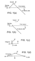
- Figures 1(a) to 1(d) illustrate schematically the optical principles of the accessory.
- Figure 1(a) shows the beam (18) reflected by the steering mirror (20) on to the sample at an angle of incidence of 45°. The beam propagates from the sample to detector.
- Figure 1(b) shows the configuration for the background measurement. In this configuration the steering mirror (20) has been pivoted to the complementary angle so that the beam is directed to the detector without being reflected from the sample. In this configuration the detector assembly is moved vertically downwards and it can be shown that the vertical distance that it has to be moved is twice the vertical separation of the sample plane and the beam (18).
- the same area of the steering mirror is illuminated at the same (complementary) angle in both configurations. Also the same region of the detector is illuminated and the pathlengths are identical. The image on the detector is, however, inverted between the two configurations which, given a typical non-uniform light beam, means that for accurate measurements either the detector has to be very uniform or an optical scrambler is required.
- Figures 1(c) and 1(d) illustrate schematically the sample configurations at the opposite ends of the range of possible angles incidence.
- Figure 1(c) shows an angle of incidence of 8° and Figure 1(d) 70°.
- These views show the need for the steering mirror (20) to translate as well as rotate.
- the detector also needs to rotate on an arc centred on the sample spot and also to move vertically downwards for the background measurement.
- the drawings also illustrate that the components of the accessory require careful location to avoid beam interruptions.
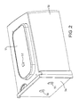
- FIGs 2 to 12 illustrate a specific embodiment of a spectrometer accessory operating on the principles shown generally in Figure 1 .
- This accessory has been designed for use with a PerkinElmer Lambda 950 spectrometer and is locatable in the compartment normally occupied by the detector of such an instrument.
- the accessory comprises a housing or cover (50) which has a top plate (51) which provides a sample location (52) at which a sample can be placed horizontally.
- the top plate can have covering layer of soft plastic material such as Teflon or Mylar to avoid possible damage to the optical surface of the sample.
- At the sample location (52) there is an aperture in the top plate (51) which can be closed by a shutter which is slidable between an open and a closed position.
- One side wall (54) of the housing (50) has an opening (55) through which the beam (28) shown in Figure 1 can propagate.
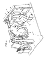
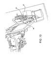
- FIGs 3 to 10 illustrate the components which are accommodated within the housing (50).
- the fold mirror is shown at (10) and is mounted on an adjustable bracket (58).
- the toroid mirror (11) is mounted diagonally upwardly from the fold mirror (10) and is suspended from the underside of the top plate on a second adjustable bracket spaced horizontally from the path length compensator (12).
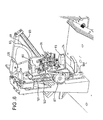
- the mirrors (14 and 15) of the path length compensator are mounted upon a casting (60) (see Figure 5 ) and this casting is linked to an assembly comprising a lead screw (61) which is drivable by a motor (62) through gears (64) so that when the motor (62) is energised the lead screw (61) rotates and causes linear movement of the pair of mirrors (14 and 15) along a path guided by slides (65 and 66). This linear movement is parallel to the path of the beam (18) shown in Figure 1 .
- the steering mirror assembly is shown at (20) and the sample location is shown at (22).
- the collector mirror is shown at (24) and the detector assembly at (26).
- the steering mirror assembly as shown in Figures 3 and 9 comprises a pivotally mounted mirror (70) with a drive assembly including a motor (76), a lead screw transmission (72), a worm drive motor (71), a worm wheel sector (73), lead screw (74) and a slide (75).
- the motor (76) seen at the centre of figure 3 can be energised to rotate the lead screw (74) and cause linear translational movement of the mirror (70) guided by the slide (75).
- the worm drive motor (71) can be used to rotate the plane of the mirror (70).
- the detector assembly is shown in more detail in Figures 4 , 6 , 7 , 8 and 9 .
- the detector assembly includes a bracket (80) which is mounted so that it is movable along an arc defined by a curved member (81) and a hub (120). This arc is centred in the lateral and vertical dimensions on the sample location (22).
- the curved member (81) is supported by an arm (82) which supports one end of a lead screw (83), which can be driven by a motor (84).
- the motor (84) is energised the lead screw rotates and causes the bracket (80) to move along an arcuate path corresponding to the arc defined by the arcuate element (81) about the sample location as pivot point.
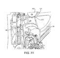
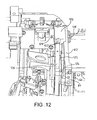
- Figures 11 and 12 show the mechanism for controlling arcuate movement of the detector assembly.
- the mechanism includes the hub (120) mounted alongside the arm (82).
- the hub (120) has an arcuate groove (121) in which are located two pins (122, 123).
- the pins (122 and 123) are disposed with their axes generally at right angles to each other.
- the pin (123) is fixed to a detector sub-plate (124) and the pin (122) rests freely on an end surface of the sub-plate.
- Two balls (124. 125) are carried by the detector sub-plate (126) and are arranged so that they can run along an arcuate track defined by the arcuate element (81).
- the detector assembly In use the detector assembly is constrained to move in an arc by the two pins (122, 123) running in the groove (121) and by the two balls (124, 125) running on the arcuate track.
- the plane of the arcuate motion is defined by the two balls and the larger (123) of the two pins which is fixed to the sub-plate (126). These elements define a three point mounting.
- the other pin (122) is free to float perpendicular to this plane, but constrains the rotation to be about the centre of rotation of the arc of the groove (121).
- the accessory is designed so that no components extend above the plane of the top-plate (51) and this precludes the use of a conventional axle for the arc rotation.
- the cross-section of the hub (120) is machined to be slightly less than a semi-circle.
- the bracket (80) supports a number of elements which form part of the detector assembly. There are two detector elements, one of these being a silicon detector (88) and the other being a lead sulphide detector (89).
- the silicon detector (88) is mounted so that it can be moved into or out of the path of radiation reflected by the collector mirror (24).
- a motor (87) is provided and can be energised to cause the detector to be moved. When the detector (88) is in the path of the beam reflected by the mirror (24) radiation does not reach the lead sulphide detector (89).
- a lightpipe (90) is associated with the lead sulphide detector (89) and arranged so that when the silicon detector is not in an operative position radiation reflected by the collector (24) is directed to a lightpipe input mirror (92) and then is reflected along a path extending through the lightpipe (90) and onto the lead sulphide detector (89).
- the reason for providing two detectors (88 and 89) is to enable the accessory to operate at different wavelengths.
- the silicon diode detector (88) is provided for relatively short wave detection. Such detectors have excellent uniformity and for reasons discussed earlier can be used without any optical scrambling.
- the lead sulphide detector (89) is provided for detection at longer wavelengths, but these detectors have a problem in that their response can be quite non-uniform over the surface area of the detector. This means that it is necessary to use an optical scrambler in order to counteract the effects of such non-uniformities.
- the light pipe (90) acts as an optical scrambler and it has been found to be particularly suitable in this application.
- the lightpipe comprises a glass rod with smooth sides polished at both ends and selected to have good transmission over the full spectral range.
- a particularly suitable glass is Suprasil 300, which has excellent transmission to beyond 2500 nm.
- an image of the sample is formed by the concave lightpipe input mirror (92) onto the input end of the lightpipe (90). Multiple internal reflections in the lightpipe then scramble the image to produce a substantially uniform patch of light at the output end of the lightpipe. This light is then refocussed onto the lead sulphide detector (89) by a lightpipe output mirror (93).
- the scrambling ensures that distribution of light emerging from the lightpipe remains substantially unchanged so that even if the detector is inhomogeneous the output signal is unchanged either for small image movements or for image inversion.
- the assembly of components mounted on bracket (80) is also movable linearly relative to the sample position for reasons explained earlier and this is achieved by means of a motor (100).
- the motor (100) can be energised to rotate a lead screw (101) and this causes the detector assembly to move upwardly or downwardly, the movement being guided by a slide (102).
- the accessory has an electronics unit (104) which can be coupled to the processing circuitry of the spectrometer and is used to provide signals for energising the motors in order to correctly position of the moveable components for the particular reflectance measurement being carried out.
- Figure 13 illustrates the relative position of the components of the accessory when a reflectivity measurement is carried out on a sample mounted at the sample location (22) and the beam is incident on the sample at an angle of 70 degrees.
- Figure 14 shows the position of the components for carrying out what is known as a baseline measurement corresponding to the 70 degree measurement. In this configuration the beam does not reflect from the sample.
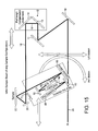
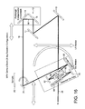
- Figures 15 and 16 are views corresponding to those of Figures 13 and 14 , but illustrate the situation where the components have been adjusted to a position in which the radiation is incident on the sample at an angle of 8 degrees.
- 8 Degrees and 70 degrees represent the end points of the range of angles over which the accessory can be used to measure reflectance of a sample. It will be appreciated that by appropriate movement of the movable components of the accessory a measurement of the reflectance of a sample can be carried out at any angle in the range 8 degrees to 70 degrees.
- the spectrometer produces a reference beam as well as a sample beam.
- the accessory includes reference beam mirrors (110, 111, and 112) and a reference beam detector (114) (see Figure 8 ), but a detailed description of these elements is not given as it is not necessary for an understanding of the present invention.
- a particularly significant feature of the design of accessory described above is that all the components of the accessory are disposed below the horizontal surface of the top plate (51).
Landscapes
- Physics & Mathematics (AREA)
- Spectroscopy & Molecular Physics (AREA)
- General Physics & Mathematics (AREA)
- Health & Medical Sciences (AREA)
- Life Sciences & Earth Sciences (AREA)
- Chemical & Material Sciences (AREA)
- Analytical Chemistry (AREA)
- Biochemistry (AREA)
- General Health & Medical Sciences (AREA)
- Immunology (AREA)
- Pathology (AREA)
- Investigating Or Analysing Materials By Optical Means (AREA)
- Spectrometry And Color Measurement (AREA)
Priority Applications (1)
| Application Number | Priority Date | Filing Date | Title |
|---|---|---|---|
| EP08075194.4A EP1939595B1 (de) | 2004-01-20 | 2004-01-20 | Messung von spekulare Reflexion einer Probe |
Applications Claiming Priority (2)
| Application Number | Priority Date | Filing Date | Title |
|---|---|---|---|
| EP08075194.4A EP1939595B1 (de) | 2004-01-20 | 2004-01-20 | Messung von spekulare Reflexion einer Probe |
| EP04250265.8A EP1557652B1 (de) | 2004-01-20 | 2004-01-20 | Vorrichtung zur messung der spekulare reflektion einer probe |
Related Parent Applications (2)
| Application Number | Title | Priority Date | Filing Date |
|---|---|---|---|
| EP04250265.8A Division EP1557652B1 (de) | 2004-01-20 | 2004-01-20 | Vorrichtung zur messung der spekulare reflektion einer probe |
| EP04250265.8A Division-Into EP1557652B1 (de) | 2004-01-20 | 2004-01-20 | Vorrichtung zur messung der spekulare reflektion einer probe |
Publications (3)
| Publication Number | Publication Date |
|---|---|
| EP1939595A2 true EP1939595A2 (de) | 2008-07-02 |
| EP1939595A3 EP1939595A3 (de) | 2009-05-06 |
| EP1939595B1 EP1939595B1 (de) | 2016-01-20 |
Family
ID=34626539
Family Applications (4)
| Application Number | Title | Priority Date | Filing Date |
|---|---|---|---|
| EP08075194.4A Expired - Lifetime EP1939595B1 (de) | 2004-01-20 | 2004-01-20 | Messung von spekulare Reflexion einer Probe |
| EP04250265.8A Expired - Lifetime EP1557652B1 (de) | 2004-01-20 | 2004-01-20 | Vorrichtung zur messung der spekulare reflektion einer probe |
| EP08075196.9A Expired - Lifetime EP1950541B1 (de) | 2004-01-20 | 2004-01-20 | Messung von spekuklarer Reflexion einer Probe |
| EP08075195A Withdrawn EP1944588A3 (de) | 2004-01-20 | 2004-01-21 | Messung von spekularer Reflexion einer Probe |
Family Applications After (3)
| Application Number | Title | Priority Date | Filing Date |
|---|---|---|---|
| EP04250265.8A Expired - Lifetime EP1557652B1 (de) | 2004-01-20 | 2004-01-20 | Vorrichtung zur messung der spekulare reflektion einer probe |
| EP08075196.9A Expired - Lifetime EP1950541B1 (de) | 2004-01-20 | 2004-01-20 | Messung von spekuklarer Reflexion einer Probe |
| EP08075195A Withdrawn EP1944588A3 (de) | 2004-01-20 | 2004-01-21 | Messung von spekularer Reflexion einer Probe |
Country Status (2)
| Country | Link |
|---|---|
| US (2) | US7595884B2 (de) |
| EP (4) | EP1939595B1 (de) |
Families Citing this family (2)
| Publication number | Priority date | Publication date | Assignee | Title |
|---|---|---|---|---|
| DE102014215193A1 (de) * | 2014-08-01 | 2016-02-04 | Carl Zeiss Spectroscopy Gmbh | Messanordnung zur Reflexionsmessung |
| JP6849405B2 (ja) * | 2016-11-14 | 2021-03-24 | 浜松ホトニクス株式会社 | 分光計測装置及び分光計測システム |
Citations (4)
| Publication number | Priority date | Publication date | Assignee | Title |
|---|---|---|---|---|
| US5106196A (en) | 1990-08-21 | 1992-04-21 | Brierley Philip R | Single adjustment specular reflection accessory for spectroscopy |
| US5262845A (en) | 1992-06-08 | 1993-11-16 | Harrick Scientific Corporation | Optical accessory for variable angle reflection spectroscopy |
| EP0713082A2 (de) | 1994-11-17 | 1996-05-22 | Ford Motor Company Limited | Optikmodul für ein Spektrometer |
| US6310348B1 (en) | 1999-06-25 | 2001-10-30 | Ramspec Corporation | Spectroscopic accessory for examining films and coatings on solid surfaces |
Family Cites Families (10)
| Publication number | Priority date | Publication date | Assignee | Title |
|---|---|---|---|---|
| US3701589A (en) * | 1968-11-08 | 1972-10-31 | Heath Co | Variable width slit mechanism for use in a scanning monochromator |
| US4657390A (en) * | 1985-02-21 | 1987-04-14 | Laser Precision Corporation | Universal spectrometer system having modular sampling chamber |
| US4712912A (en) * | 1986-03-10 | 1987-12-15 | Spectra-Tech, Inc. | Spectrophotometric image scrambler for full aperture microspectroscopy |
| US5048970A (en) * | 1990-06-29 | 1991-09-17 | Nicolas J. Harrick | Optical attachment for variable angle reflection spectroscopy |
| US5088821A (en) * | 1990-06-29 | 1992-02-18 | Nicolas J. Harrick | Spectroscopic analysis system with remote terminals |
| US6184980B1 (en) * | 1995-02-27 | 2001-02-06 | The Board Of Governors For Higher Education, State Of Rhode Island And Providence Plantations | Fiber optic sensor for petroleum |
| KR100238215B1 (ko) * | 1996-11-13 | 2000-01-15 | 윤종용 | 웨이퍼 표면분석 장치 및 이를 이용한 웨이퍼 표면 분석방법 |
| AUPR420201A0 (en) * | 2001-04-04 | 2001-05-03 | Varian Australia Pty Ltd | Measuring specular reflectance of a sample |
| US6862091B2 (en) * | 2001-04-11 | 2005-03-01 | Inlight Solutions, Inc. | Illumination device and method for spectroscopic analysis |
| US7265844B2 (en) * | 2003-04-10 | 2007-09-04 | Wisconsin Alumni Research Foundation | Horizontal surface plasmon resonance instrument with improved light path |
-
2004
- 2004-01-20 EP EP08075194.4A patent/EP1939595B1/de not_active Expired - Lifetime
- 2004-01-20 EP EP04250265.8A patent/EP1557652B1/de not_active Expired - Lifetime
- 2004-01-20 EP EP08075196.9A patent/EP1950541B1/de not_active Expired - Lifetime
- 2004-01-21 EP EP08075195A patent/EP1944588A3/de not_active Withdrawn
-
2005
- 2005-01-21 US US11/040,535 patent/US7595884B2/en not_active Expired - Lifetime
-
2009
- 2009-09-01 US US12/552,006 patent/US8345235B2/en not_active Expired - Fee Related
Patent Citations (4)
| Publication number | Priority date | Publication date | Assignee | Title |
|---|---|---|---|---|
| US5106196A (en) | 1990-08-21 | 1992-04-21 | Brierley Philip R | Single adjustment specular reflection accessory for spectroscopy |
| US5262845A (en) | 1992-06-08 | 1993-11-16 | Harrick Scientific Corporation | Optical accessory for variable angle reflection spectroscopy |
| EP0713082A2 (de) | 1994-11-17 | 1996-05-22 | Ford Motor Company Limited | Optikmodul für ein Spektrometer |
| US6310348B1 (en) | 1999-06-25 | 2001-10-30 | Ramspec Corporation | Spectroscopic accessory for examining films and coatings on solid surfaces |
Also Published As
| Publication number | Publication date |
|---|---|
| US20050185185A1 (en) | 2005-08-25 |
| EP1939595B1 (de) | 2016-01-20 |
| EP1950541A2 (de) | 2008-07-30 |
| EP1557652A1 (de) | 2005-07-27 |
| EP1939595A3 (de) | 2009-05-06 |
| US20090323072A1 (en) | 2009-12-31 |
| EP1950541B1 (de) | 2019-05-08 |
| EP1944588A3 (de) | 2009-05-06 |
| EP1557652B1 (de) | 2019-04-17 |
| US8345235B2 (en) | 2013-01-01 |
| US7595884B2 (en) | 2009-09-29 |
| EP1950541A3 (de) | 2009-05-06 |
| EP1944588A2 (de) | 2008-07-16 |
Similar Documents
| Publication | Publication Date | Title |
|---|---|---|
| US5106196A (en) | Single adjustment specular reflection accessory for spectroscopy | |
| US5048970A (en) | Optical attachment for variable angle reflection spectroscopy | |
| US7576863B2 (en) | Horizontal surface plasmon resonance sensor apparatus | |
| JP6113730B2 (ja) | 放出及び透過光学分光計 | |
| US5864139A (en) | Confocal microspectrometer system | |
| US4790659A (en) | Optical sample illumination device for a spectroscopic ellipsometer having a high lateral resolution | |
| US7265844B2 (en) | Horizontal surface plasmon resonance instrument with improved light path | |
| CN106574866B (zh) | 用于反射测量的测量装置 | |
| US20120033213A1 (en) | Spectrograph having multiple wavelength ranges for high resolution raman spectroscopy | |
| US4285597A (en) | Goniophotometer for measuring the gloss and/or light diffusion of surfaces | |
| JPH0797078B2 (ja) | 赤外線顕微分光測定装置 | |
| US8345235B2 (en) | Measurement of sample reflectance | |
| US5262845A (en) | Optical accessory for variable angle reflection spectroscopy | |
| JP3609029B2 (ja) | 検出装置及び液体試料測定装置 | |
| US4676652A (en) | Multiple pass optical system | |
| KR20100110301A (ko) | 액체, 페이스트, 또는 고체 물질들의 특성치들을 분석하기 위한 분광계 측정 헤드 | |
| CN103154704B (zh) | 对液体样品进行光度分析的装置和用于其的样品承载件 | |
| US7224460B2 (en) | Mapping-measurement apparatus | |
| US5818046A (en) | Mid-infrared analysis system | |
| US5495363A (en) | Mirror optics with grazing incidence reflection | |
| US20110096325A1 (en) | Method and device for the spectrometric measurement of a material flow moving in the longitudinal direction | |
| JP2002372456A (ja) | 赤外分光光度計 | |
| JPH0694528A (ja) | 分光分析装置 | |
| EP4390341A1 (de) | Spektrometer mit zubehör zur messung der absoluten transmission | |
| Shaw et al. | The design of the new NPL reference spectrofluorimeter |
Legal Events
| Date | Code | Title | Description |
|---|---|---|---|
| PUAI | Public reference made under article 153(3) epc to a published international application that has entered the european phase |
Free format text: ORIGINAL CODE: 0009012 |
|
| 17P | Request for examination filed |
Effective date: 20080318 |
|
| AC | Divisional application: reference to earlier application |
Ref document number: 1557652 Country of ref document: EP Kind code of ref document: P |
|
| AK | Designated contracting states |
Kind code of ref document: A2 Designated state(s): AT BE BG CH CY CZ DE DK EE ES FI FR GB GR HU IE IT LI LU MC NL PT RO SE SI SK TR |
|
| AX | Request for extension of the european patent |
Extension state: AL LT LV MK |
|
| PUAL | Search report despatched |
Free format text: ORIGINAL CODE: 0009013 |
|
| RIC1 | Information provided on ipc code assigned before grant |
Ipc: G01J 3/44 20060101AFI20090324BHEP |
|
| RTI1 | Title (correction) |
Free format text: APPARATUS FOR MEASURING SPECULAR REFLECTANCE OF A SAMPLE |
|
| AK | Designated contracting states |
Kind code of ref document: A3 Designated state(s): AT BE BG CH CY CZ DE DK EE ES FI FR GB GR HU IE IT LI LU MC NL PT RO SE SI SK TR |
|
| AX | Request for extension of the european patent |
Extension state: AL LT LV MK |
|
| 17Q | First examination report despatched |
Effective date: 20090714 |
|
| AKX | Designation fees paid |
Designated state(s): DE GB |
|
| RAP1 | Party data changed (applicant data changed or rights of an application transferred) |
Owner name: PERKINELMER UK LIMITED |
|
| RAP1 | Party data changed (applicant data changed or rights of an application transferred) |
Owner name: PERKINELMER SINGAPORE PTE LIMITED |
|
| GRAP | Despatch of communication of intention to grant a patent |
Free format text: ORIGINAL CODE: EPIDOSNIGR1 |
|
| INTG | Intention to grant announced |
Effective date: 20150717 |
|
| GRAS | Grant fee paid |
Free format text: ORIGINAL CODE: EPIDOSNIGR3 |
|
| GRAA | (expected) grant |
Free format text: ORIGINAL CODE: 0009210 |
|
| INTG | Intention to grant announced |
Effective date: 20151209 |
|
| AC | Divisional application: reference to earlier application |
Ref document number: 1557652 Country of ref document: EP Kind code of ref document: P |
|
| AK | Designated contracting states |
Kind code of ref document: B1 Designated state(s): DE GB |
|
| REG | Reference to a national code |
Ref country code: GB Ref legal event code: FG4D |
|
| REG | Reference to a national code |
Ref country code: DE Ref legal event code: R096 Ref document number: 602004048579 Country of ref document: DE |
|
| REG | Reference to a national code |
Ref country code: DE Ref legal event code: R097 Ref document number: 602004048579 Country of ref document: DE |
|
| PLBE | No opposition filed within time limit |
Free format text: ORIGINAL CODE: 0009261 |
|
| STAA | Information on the status of an ep patent application or granted ep patent |
Free format text: STATUS: NO OPPOSITION FILED WITHIN TIME LIMIT |
|
| 26N | No opposition filed |
Effective date: 20161021 |
|
| PGFP | Annual fee paid to national office [announced via postgrant information from national office to epo] |
Ref country code: GB Payment date: 20221201 Year of fee payment: 20 |
|
| PGFP | Annual fee paid to national office [announced via postgrant information from national office to epo] |
Ref country code: DE Payment date: 20221123 Year of fee payment: 20 |
|
| P01 | Opt-out of the competence of the unified patent court (upc) registered |
Effective date: 20230601 |
|
| REG | Reference to a national code |
Ref country code: DE Ref legal event code: R071 Ref document number: 602004048579 Country of ref document: DE |
|
| REG | Reference to a national code |
Ref country code: GB Ref legal event code: PE20 Expiry date: 20240119 |
|
| PG25 | Lapsed in a contracting state [announced via postgrant information from national office to epo] |
Ref country code: GB Free format text: LAPSE BECAUSE OF EXPIRATION OF PROTECTION Effective date: 20240119 |