EP1939905A2 - Schalterblech - Google Patents
Schalterblech Download PDFInfo
- Publication number
- EP1939905A2 EP1939905A2 EP07025047A EP07025047A EP1939905A2 EP 1939905 A2 EP1939905 A2 EP 1939905A2 EP 07025047 A EP07025047 A EP 07025047A EP 07025047 A EP07025047 A EP 07025047A EP 1939905 A2 EP1939905 A2 EP 1939905A2
- Authority
- EP
- European Patent Office
- Prior art keywords
- sheet
- dome
- switch sheet
- switch
- contact
- Prior art date
- Legal status (The legal status is an assumption and is not a legal conclusion. Google has not performed a legal analysis and makes no representation as to the accuracy of the status listed.)
- Granted
Links
- 239000000758 substrate Substances 0.000 claims abstract description 11
- 239000004020 conductor Substances 0.000 claims abstract description 6
- 238000004049 embossing Methods 0.000 claims description 7
- 229920001225 polyester resin Polymers 0.000 claims description 5
- 229920002379 silicone rubber Polymers 0.000 claims description 4
- 239000000463 material Substances 0.000 claims description 3
- 229910052751 metal Inorganic materials 0.000 claims description 3
- 239000002184 metal Substances 0.000 claims description 3
- 150000002739 metals Chemical class 0.000 claims description 3
- 230000000052 comparative effect Effects 0.000 description 18
- 238000006073 displacement reaction Methods 0.000 description 8
- 239000000853 adhesive Substances 0.000 description 7
- 238000002474 experimental method Methods 0.000 description 4
- 238000004519 manufacturing process Methods 0.000 description 4
- 239000004645 polyester resin Substances 0.000 description 3
- 239000011159 matrix material Substances 0.000 description 2
- 229920001690 polydopamine Polymers 0.000 description 2
- 230000002265 prevention Effects 0.000 description 2
- 238000004080 punching Methods 0.000 description 2
- 238000010008 shearing Methods 0.000 description 2
- 229910001220 stainless steel Inorganic materials 0.000 description 2
- 229910000906 Bronze Inorganic materials 0.000 description 1
- RYGMFSIKBFXOCR-UHFFFAOYSA-N Copper Chemical compound [Cu] RYGMFSIKBFXOCR-UHFFFAOYSA-N 0.000 description 1
- OAICVXFJPJFONN-UHFFFAOYSA-N Phosphorus Chemical compound [P] OAICVXFJPJFONN-UHFFFAOYSA-N 0.000 description 1
- 239000004698 Polyethylene Substances 0.000 description 1
- NIXOWILDQLNWCW-UHFFFAOYSA-N acrylic acid group Chemical group C(C=C)(=O)O NIXOWILDQLNWCW-UHFFFAOYSA-N 0.000 description 1
- 230000001070 adhesive effect Effects 0.000 description 1
- 229910045601 alloy Inorganic materials 0.000 description 1
- 239000000956 alloy Substances 0.000 description 1
- 229910052782 aluminium Inorganic materials 0.000 description 1
- XAGFODPZIPBFFR-UHFFFAOYSA-N aluminium Chemical compound [Al] XAGFODPZIPBFFR-UHFFFAOYSA-N 0.000 description 1
- 239000010974 bronze Substances 0.000 description 1
- 239000003795 chemical substances by application Substances 0.000 description 1
- 229910052802 copper Inorganic materials 0.000 description 1
- 239000010949 copper Substances 0.000 description 1
- KUNSUQLRTQLHQQ-UHFFFAOYSA-N copper tin Chemical compound [Cu].[Sn] KUNSUQLRTQLHQQ-UHFFFAOYSA-N 0.000 description 1
- 230000003247 decreasing effect Effects 0.000 description 1
- 230000005489 elastic deformation Effects 0.000 description 1
- 238000005242 forging Methods 0.000 description 1
- 238000000034 method Methods 0.000 description 1
- 238000012986 modification Methods 0.000 description 1
- 230000004048 modification Effects 0.000 description 1
- 238000007747 plating Methods 0.000 description 1
- 229920000728 polyester Polymers 0.000 description 1
- -1 polyethylene Polymers 0.000 description 1
- 229920000573 polyethylene Polymers 0.000 description 1
- 238000003825 pressing Methods 0.000 description 1
- 230000002787 reinforcement Effects 0.000 description 1
- 229920005989 resin Polymers 0.000 description 1
- 239000011347 resin Substances 0.000 description 1
- 150000003376 silicon Chemical class 0.000 description 1
- 239000010935 stainless steel Substances 0.000 description 1
- 230000007306 turnover Effects 0.000 description 1
Images





Classifications
-
- H—ELECTRICITY
- H01—ELECTRIC ELEMENTS
- H01H—ELECTRIC SWITCHES; RELAYS; SELECTORS; EMERGENCY PROTECTIVE DEVICES
- H01H13/00—Switches having rectilinearly-movable operating part or parts adapted for pushing or pulling in one direction only, e.g. push-button switch
- H01H13/70—Switches having rectilinearly-movable operating part or parts adapted for pushing or pulling in one direction only, e.g. push-button switch having a plurality of operating members associated with different sets of contacts, e.g. keyboard
- H01H13/7006—Switches having rectilinearly-movable operating part or parts adapted for pushing or pulling in one direction only, e.g. push-button switch having a plurality of operating members associated with different sets of contacts, e.g. keyboard comprising a separate movable contact element for each switch site, all other elements being integrated in layers
-
- H—ELECTRICITY
- H01—ELECTRIC ELEMENTS
- H01H—ELECTRIC SWITCHES; RELAYS; SELECTORS; EMERGENCY PROTECTIVE DEVICES
- H01H13/00—Switches having rectilinearly-movable operating part or parts adapted for pushing or pulling in one direction only, e.g. push-button switch
- H01H13/70—Switches having rectilinearly-movable operating part or parts adapted for pushing or pulling in one direction only, e.g. push-button switch having a plurality of operating members associated with different sets of contacts, e.g. keyboard
- H01H13/84—Switches having rectilinearly-movable operating part or parts adapted for pushing or pulling in one direction only, e.g. push-button switch having a plurality of operating members associated with different sets of contacts, e.g. keyboard characterised by ergonomic functions, e.g. for miniature keyboards; characterised by operational sensory functions, e.g. sound feedback
- H01H13/85—Switches having rectilinearly-movable operating part or parts adapted for pushing or pulling in one direction only, e.g. push-button switch having a plurality of operating members associated with different sets of contacts, e.g. keyboard characterised by ergonomic functions, e.g. for miniature keyboards; characterised by operational sensory functions, e.g. sound feedback characterised by tactile feedback features
-
- H—ELECTRICITY
- H01—ELECTRIC ELEMENTS
- H01H—ELECTRIC SWITCHES; RELAYS; SELECTORS; EMERGENCY PROTECTIVE DEVICES
- H01H2205/00—Movable contacts
- H01H2205/016—Separate bridge contact
-
- H—ELECTRICITY
- H01—ELECTRIC ELEMENTS
- H01H—ELECTRIC SWITCHES; RELAYS; SELECTORS; EMERGENCY PROTECTIVE DEVICES
- H01H2215/00—Tactile feedback
- H01H2215/004—Collapsible dome or bubble
- H01H2215/026—Eccentric actuation
-
- H—ELECTRICITY
- H01—ELECTRIC ELEMENTS
- H01H—ELECTRIC SWITCHES; RELAYS; SELECTORS; EMERGENCY PROTECTIVE DEVICES
- H01H2217/00—Facilitation of operation; Human engineering
- H01H2217/01—Off centre actuation
-
- H—ELECTRICITY
- H01—ELECTRIC ELEMENTS
- H01H—ELECTRIC SWITCHES; RELAYS; SELECTORS; EMERGENCY PROTECTIVE DEVICES
- H01H2221/00—Actuators
- H01H2221/05—Force concentrator; Actuating dimple
-
- H—ELECTRICITY
- H01—ELECTRIC ELEMENTS
- H01H—ELECTRIC SWITCHES; RELAYS; SELECTORS; EMERGENCY PROTECTIVE DEVICES
- H01H2227/00—Dimensions; Characteristics
- H01H2227/026—Separate dome contact
-
- H—ELECTRICITY
- H01—ELECTRIC ELEMENTS
- H01H—ELECTRIC SWITCHES; RELAYS; SELECTORS; EMERGENCY PROTECTIVE DEVICES
- H01H2229/00—Manufacturing
- H01H2229/05—Forming; Half-punching
-
- Y—GENERAL TAGGING OF NEW TECHNOLOGICAL DEVELOPMENTS; GENERAL TAGGING OF CROSS-SECTIONAL TECHNOLOGIES SPANNING OVER SEVERAL SECTIONS OF THE IPC; TECHNICAL SUBJECTS COVERED BY FORMER USPC CROSS-REFERENCE ART COLLECTIONS [XRACs] AND DIGESTS
- Y10—TECHNICAL SUBJECTS COVERED BY FORMER USPC
- Y10T—TECHNICAL SUBJECTS COVERED BY FORMER US CLASSIFICATION
- Y10T156/00—Adhesive bonding and miscellaneous chemical manufacture
- Y10T156/10—Methods of surface bonding and/or assembly therefor
- Y10T156/1002—Methods of surface bonding and/or assembly therefor with permanent bending or reshaping or surface deformation of self sustaining lamina
Definitions
- Apparatuses consistent with the present invention relate to switch sheets applied to electronic devices, in particular compact electronic devices such as mobile phones.
- Compact electronic devices such as mobile phones, digital cameras, PDAs, MD or CD players and such are in general equipped with a keypad including a plurality of switches for command input, in which the switches are arrange in a row or a matrix.
- the keypad is often made in a sheet-like shape in pursuit of compactness.
- a sheet-like keypad is typically comprised of a substrate with conductive contacts printed thereon, and dome-like key tops respectively covering the contacts. When an operator presses down one of the key tops, the key top deforms to be in contact with the corresponding contact, and thereby conduction is established (the switch is switched ON).
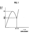
- FIG. 1 illustrates a typical load-displacement curve about such a dome-like key top.
- P1 When an operator is pressing down the key top as far as a load thereon is still under a threshold of P1, displacement thereof increases as the load increases but is not sufficient to have the contacts get in contact. More specifically, the key function as an elastic body against the load. However, if the load reaches the threshold of P1, the displacement keeps increasing but the load required for the displacement starts decreasing. Finally the displacement reaches S3 and then the contacts get in contact (the switch is ON).
- This profile of the load-displacement curve gives a click feel to the operator and thereby the operator can ascertain if the switch is ON.
- Certain embodiments of the present invention provide a switch sheet providing a better click feel and having improved durability.
- a switch sheet is used in combination with a substrate having a first contact and a second contact.
- the switch sheet is comprised of an elastically deformable dome including a conductive material; and a sheet covering the dome and including an embossment projecting from a top of the dome, the sheet being so dimensioned as to have the dome suspended over the first contact and in contact with the second contact.
- the embossment is produced by embossing.
- the switch sheet is further comprised of an intervening member intervening between the dome and the sheet so as to have the embossment projecting.
- the intervening member is made of a material selected from the group of silicon rubber, metals and polyester resins.
- a switch sheet 1 of the embodiment is applied to a keypad 3 for operation of compact electronic devices such as mobile phones, digital cameras, PDAs, MD or CD players and such.
- the keypad 3 is comprised of one or more switch keys forming a row or a matrix as shown in Fig. 3 .
- the keypad 3 is comprised of a substrate 5 made of a PCB (Printed Circuit Board) or a FPC (Flexible Printed Circuit) and one or more contacts 7A made of any conductive material formed thereon.
- a substrate 5 made of a PCB (Printed Circuit Board) or a FPC (Flexible Printed Circuit) and one or more contacts 7A made of any conductive material formed thereon.
- One or more circular contacts 7B respectively enclosing the contacts 7A are further formed on the substrate 5.
- the contacts 7A are respectively disposed at centers of the circular contacts 7B. Production of these contacts 7A and 7B may be carried out by, but not limited to, a well-known printing or plating method.
- the keypad 3 is further comprised of the switch sheet 1 and a key mat 9 for covering the switch sheet 1.
- the key mat 9 is so disposed as to be opposed to and close to the switch sheet 1 for enabling actuation of the switch sheet 1 by a press of the key mat 9.
- the key mat 9 may be made of, but not limited to, a silicon rubber.
- the key mat 9 may have pads 9A unitarily projecting therefrom or adhered thereon for the purpose of reinforcement thereof and indication of keys.
- the switch sheet 1 is used in combination with the substrate 5 and the key mat 9 as described above.
- the switch sheet 1 is comprised of elastically deformable domes 11 made of a conductive material.
- the domes 11 are formed in a dome-like or semi-spherical shape. Whereas its shape is not limited to the dome-like shape, this shape may be preferable for elastic deformation by a press and providing a click feel.
- the domes 11 may be produced by, though not limited to, punching, presswork or forging from a sheet of a proper elastic conductive material such as stainless steels, copper, aluminum or these alloys.
- the outer diameter of the domes 11 is made corresponding to the circular contacts 7B.
- the switch sheet 1 is further comprised of a covering sheet 13 made of any resin for example, which closely covers the domes 11.
- the covering sheet 13 follows curved surfaces of the domes 11 and carries out positioning of the domes 11 so as to have the domes 11 respectively suspended over the contacts 7A and in contact with the circular contacts 7B.
- the covering sheet 13 is comprised of a sheet 13A and an adhesive agent 13B on its surface opposed to the substrate 5 so that the covering sheet 13 adheres to the substrate 5.
- tops of the domes 11 and the contacts 7A are respectively aligned as shown in Fig. 3 . Therefore, when any of the tops of the domes 11 is pressed down, the top comes in contact with the corresponding contact 7A to establish conduction among the contact 7B, the dome 11 and the contact 7A as shown in Fig. 2B .
- intervening members 15 are disposed on the respective tops of the domes 11.
- Corresponding cites of the covering sheet 13 has embossments 19 respectively projecting upward from the tops of the domes 11.
- the intervening members 15 are formed into, but not limited to, a low columnar or cuboid shape to have a plane top face. It is advantageous to improvement in quality of symmetry of deformation around the center of the dome 11 at a time of being pressed down, even if the pressure force is inclined or has an offset from the center.
- the height of the intervening member 15, which may be corresponding to the height of the embossment 19, is preferably from 1/3 to 2/3 of a stroke of (or the height of) the dome 11 from a steady state to a state where the dome 11 is in contact with the contact 7A.
- the height of the intervening member 15 is preferably from 0.05mm to 1.0mm. The reason is that heights greater than 0.05mm help an operator press the dome 11 and heights smaller than 1.0mm effectively prevent the embossment 19 from receiving inclined or shearing force. In particular, prevention of inclined or shearing force leads to improvement of durability.
- the diameter of the intervening member 15 is preferably from 1/4 to 3/4 of the diameter of the dome 11.
- the diameter of the intervening member 15 is preferably from 1.0mm to 3.0mm. The reason is that diameters greater than 1.0mm help an operator press the dome 11 and diameters smaller than 3.0mm do not force a rimportion of the dome 11 to excessively deform. In particular, prevention of excessive deformation leads to improvement of durability.
- the intervening members 15 may be made from silicon rubber, metals or polyster resins. These materials are preferable for operability of the switch sheet 1 as being not softer than the key mat 9.
- the sheet 13A of the covering sheet 13 is formed of a polyethylene or polyester sheet having a thickness of from 25 ⁇ m to 75 ⁇ m, for example.
- the adhesive agent 13B is formed of an adhesive or sticking agent of an acrylic series or silicon series, for example.
- the adhesive agent 13B may be provided only on surfaces opposed to the substrate 5 but may be provided also on surfaces opposed to the domes 11.
- the covering sheet 13 may be treated with embossing so as to have a structure fitting with the domes 11.
- the embossments 19 may be also produced by embossing.
- the intervening members 15 are respectively fit into the interiors of the embossments 19.
- the switch sheet 1 may further have biasing means such as springs (not shown) for biasing the key mat 9 in a direction departing from the substrate 5 (upward in Fig. 2A ).
- biasing means such as springs (not shown) for biasing the key mat 9 in a direction departing from the substrate 5 (upward in Fig. 2A ).
- the switch sheet 1 is structured in the way as described above, when an operator presses his/her finger onto one of the pads 9A of the key mat 9, the corresponding embossment 19 is pressed down by the descending key mat 9 and thereby the top of the corresponding dome 11 starts deforming downward as shown in Fig. 2B .
- the switch key is switched ON.
- the switch sheet 1 also provides the operator a click feel. A detailed description about the click feel will be given later.
- a production method of the switch sheet 1 will be exemplarily described hereinafter.
- the sheet 13A of any of polyester resins such as PET having a thickness of from 25 ⁇ m to 75 ⁇ m coated with the adhesive agent 13B is treated with embossing to form dome-like embossments which respectively fit with the domes 11 and the embossments 19 respectively at the centers thereof.
- the embossing is carried out using embossing dies respectively having male and female shapes of the embossments.
- the intervening members 15 are produced by punching a film of a polyester resin such as PET having a thickness of 125mm, for example.
- the domes 11 are produced by presswork from a sheet of a stainless steel or a phosphor bronze to form a semispherical shape.
- the covering sheet 13, the intervening members 15 and the domes 11 are aligned using proper jigs (not shown) as shown in Fig. 4 and then adhered with each other. Thereby the switch sheet 1 is produced.
- Fig. 5A illustrates a structure of the switch sheet 21 of the comparative example.
- the switch sheet 21 is comprised of an elastically deformable dome 11, a covering sheet 13A, and an adhesive agent 13B as identical to the switch sheet 1 of the working example, but an intervening member 15 and an embossment 19 are omitted from the switch sheet 21.
- Fig. 5B illustrates a structure of the switch sheet 1 of the working example, which is comprised of an elastically deformable dome 11, a covering sheet 13A, an adhesive agent 13B, an intervening member 15 disposed at the top of the dome 11, and an embossment 19 projecting therefrom.
- the height h of the intervening member 15 is 0.125mm and the diameter d is 1.5mm for example.
- the height H of the embossment 19 is 0.126mm and the diameter D is 2.3mm for example.
- the switch sheets 1, 21 were pressed down by various actuators having diameters of 1.0mm ⁇ , 1.5mm ⁇ , 2.0mm ⁇ and 2.6mm ⁇ , and respective loads were measured at various points having offsets from the center of the dome 11.
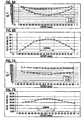
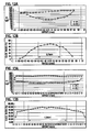
- maximum loads P1 and the minimum loads P2 were respectively measured and plotted in Figs. 6A-13A as in relation to the offsets.
- Quality of a click feel can be evaluated on the basis of the maximum load P1, the click ratio and a stroke S2.
- the maximum load P1 relates to a force required for operation of the switch. The greater the click ratio is, the better a click feel which an operator enjoys becomes, thereby the operator easily ascertains if the switch is ON. The same applies to the stroke S2.
- the curves of the minimum loads P2 show more noticeable tendency of having minimums around the points where the offset is zero or near zero, as compared with those of the maximum loads P1.
- the click ratios calculated from P1 and P2 resultantly have maximums around the points where the offset is zero or near zero.
- a range of the offsets where the click ratios are greater than 40% will be referred to as a "stable range" hereinafter, where a click feel may be sufficiently good.
- Figs. 6A and 6B show results about the switch sheet 21 of the comparative example (without an embossment) pressed by the actuator having the diameter of 1.0mm ⁇ . A stable range where the click ratios are greater than 40% is 0.5mm.
- Figs. 7A and 7B show results about the switch sheet 1 of the working example (with an embossment) pressed by the same actuator having the diameter of 1.0mm ⁇ . A stable range of the working example is 0.6mm.
- Figs. 8A and 8B show results about the switch sheet 21 of the comparative example pressed by the actuator having the diameter of 1.5mm ⁇ . A stable range of the comparative example is 0.6mm.
- Figs. 9A and 9B show results about the switch sheet 1 of the working example pressed by the same actuator having the diameter of 1.5mm ⁇ . A stable range of the working example is 0.8mm.
- Figs. 10A and 10B show results about the switch sheet 21 of the comparative example pressed by the actuator having the diameter of 2.0mm ⁇ . A stable range of the comparative example is 0.6mm.
- Figs. 11A and 11B show results about the switch sheet 1 of the working example pressed by the same actuator having the diameter of 2.0mm ⁇ . A stable range of the working example is 1.6mm.
- Figs. 12A and 12B show results about the switch sheet 21 of the comparative example pressed by the actuator having the diameter of 2.6mm ⁇ . A stable range of the comparative example is 0.7mm.
- Figs. 13A and 13B show results about the switch sheet 1 of the working example pressed by the same actuator having the diameter of 2.6mm ⁇ . A stable range of the working example is 1.8mm.
- Table 1 Diameters of actuators (mm) Stable ranges where click ratios are greater than 40% (mm) Comparative example (without an embossment) Working example (with an embossment) 1.0 0.5 0.6 1.5 0.6 0.8 2.0 0.6 1.6 2.6 0.7 1.8
- the P2 curves of the switch sheet 1 in the graphs show gentler slopes than those of the switch sheet 21.
- the switch sheet 1 of the working example (with an embossment) has broader stable ranges than the switch sheet 21 of the comparative example (without an embossment).
- the experimental results demonstrate the following advantages of the switch sheet 1 as compared with the switch sheet 21.
- a spot to be pressed may be generally deviated from the center of the switch because any human being cannot act with machinelike precision.
- the switch sheet 1 may give a greater probability that the spot to be pressed comes within the stable range. Then the operator can enjoy a sufficient click feel so as to ascertain if the switch is ON.
- the broader stable range is advantageous in view of improvement of durability of the switch sheet 1.
- a dome of a switch sheet will fracture with a certain possibility if the switch sheet is subject to a great number of operations. The possibility depends on an offset of a spot to be pressed because deformation of the dome becomes less uniform or symmetric when the offset is greater.
- Table 2 shows numbers of fractured samples among 6024 samples tested in durability tests in which the samples are subject to one million operations. Table 2 Offset 0mm 0.3mm 0.5mm 0.7mm Numbers of fractured samples 8 14 14 31 (among 6024 tested samples)
- the broader stable range also leads to enabling easing tolerance of size and positioning.
- a switch sheet is usually covered with a key mat which provides a target to be pressed.
- tolerance of positioning between the switch sheet 1 and the key mat 9 may be considerably eased. Moderation in tolerance is advantageous in view of ease of production.
Landscapes
- Push-Button Switches (AREA)
Applications Claiming Priority (1)
| Application Number | Priority Date | Filing Date | Title |
|---|---|---|---|
| JP2006350436A JP5193463B2 (ja) | 2006-12-26 | 2006-12-26 | スイッチモジュール |
Publications (3)
| Publication Number | Publication Date |
|---|---|
| EP1939905A2 true EP1939905A2 (de) | 2008-07-02 |
| EP1939905A3 EP1939905A3 (de) | 2008-10-29 |
| EP1939905B1 EP1939905B1 (de) | 2010-08-04 |
Family
ID=39253894
Family Applications (1)
| Application Number | Title | Priority Date | Filing Date |
|---|---|---|---|
| EP07025047A Not-in-force EP1939905B1 (de) | 2006-12-26 | 2007-12-21 | Schalterblech |
Country Status (5)
| Country | Link |
|---|---|
| US (2) | US20080149470A1 (de) |
| EP (1) | EP1939905B1 (de) |
| JP (1) | JP5193463B2 (de) |
| CN (1) | CN101211705B (de) |
| TW (1) | TWI343063B (de) |
Cited By (3)
| Publication number | Priority date | Publication date | Assignee | Title |
|---|---|---|---|---|
| CN102683071A (zh) * | 2012-05-16 | 2012-09-19 | 中山市狮盾电器有限公司 | 一种平板开关的连动装置 |
| EP2434510A4 (de) * | 2009-05-22 | 2014-03-05 | Fujikura Ltd | Schaltvorrichtung und elektronisches gerät damit |
| TWI749840B (zh) * | 2020-10-30 | 2021-12-11 | 致伸科技股份有限公司 | 橡膠圓頂以及應用此橡膠圓頂的按鍵 |
Families Citing this family (6)
| Publication number | Priority date | Publication date | Assignee | Title |
|---|---|---|---|---|
| US20100109921A1 (en) * | 2008-10-30 | 2010-05-06 | Sony Ericsson Mobile Communications Ab | Dome sheet and key pad |
| CN102101370B (zh) * | 2010-10-20 | 2013-04-17 | 天津市中环高科技有限公司 | 手机透镜保护膜的自动装配方法 |
| KR20120049630A (ko) * | 2010-11-09 | 2012-05-17 | 주식회사 이노칩테크놀로지 | 다방향 입력 장치 |
| JP6638256B2 (ja) * | 2015-08-24 | 2020-01-29 | ヤマハ株式会社 | 反力発生装置及び電子楽器の鍵盤装置 |
| CN206849740U (zh) * | 2017-05-11 | 2018-01-05 | 陈国平 | 一种锅仔片及其带有该锅仔片的电子卡片 |
| CN113871237B (zh) * | 2020-06-30 | 2024-03-22 | 宏碁股份有限公司 | 输入装置的按压结构 |
Citations (6)
| Publication number | Priority date | Publication date | Assignee | Title |
|---|---|---|---|---|
| JPS60112212A (ja) | 1983-11-18 | 1985-06-18 | 松下電器産業株式会社 | 押釦スイツチ |
| DE8619781U1 (de) | 1986-07-23 | 1987-04-02 | Picker International GmbH, 8000 München | Bedienfeldplatte eines medizinischen Gerätes, insbesondere eines Röntgengenerators |
| JP2001135189A (ja) | 1999-11-02 | 2001-05-18 | Sony Corp | スイッチ |
| JP2003100170A (ja) | 2001-09-21 | 2003-04-04 | Seiko Precision Inc | スイッチユニット |
| JP2006127800A (ja) | 2004-10-26 | 2006-05-18 | Alps Electric Co Ltd | 板ばね付きシート及びこれを用いたスイッチ装置 |
| US20060180455A1 (en) | 2005-02-02 | 2006-08-17 | Yoshiro Sano | Movable contact element and panel switch using the same |
Family Cites Families (7)
| Publication number | Priority date | Publication date | Assignee | Title |
|---|---|---|---|---|
| US4307268A (en) * | 1978-11-17 | 1981-12-22 | Rogers Corporation | Tactile element and keyboard including the tactile element |
| US4245138A (en) * | 1978-11-17 | 1981-01-13 | Rogers Corporation | Tactile element and keyboard including the tactile element |
| JPH08258147A (ja) * | 1995-03-22 | 1996-10-08 | Fujikura Ltd | エンボスシートの製造方法 |
| JP2001307591A (ja) * | 2000-04-21 | 2001-11-02 | Nec Saitama Ltd | 電子装置のキーボタン構造 |
| JP2002367478A (ja) * | 2001-06-08 | 2002-12-20 | Alps Electric Co Ltd | 接点板付きシート及びこれを用いたスイッチ装置及びその製造方法 |
| JP2003077366A (ja) * | 2001-09-05 | 2003-03-14 | Seiko Precision Inc | スイッチユニット |
| JP2005353412A (ja) * | 2004-06-10 | 2005-12-22 | Alps Electric Co Ltd | 板バネ付シート、及びこの板バネ付シートを使用したスイッチ装置 |
-
2006
- 2006-12-26 JP JP2006350436A patent/JP5193463B2/ja not_active Expired - Fee Related
-
2007
- 2007-12-21 EP EP07025047A patent/EP1939905B1/de not_active Not-in-force
- 2007-12-21 US US11/962,629 patent/US20080149470A1/en not_active Abandoned
- 2007-12-25 TW TW096149954A patent/TWI343063B/zh not_active IP Right Cessation
- 2007-12-26 CN CN2007103053068A patent/CN101211705B/zh not_active Expired - Fee Related
-
2010
- 2010-03-05 US US12/718,307 patent/US20100154981A1/en not_active Abandoned
Patent Citations (6)
| Publication number | Priority date | Publication date | Assignee | Title |
|---|---|---|---|---|
| JPS60112212A (ja) | 1983-11-18 | 1985-06-18 | 松下電器産業株式会社 | 押釦スイツチ |
| DE8619781U1 (de) | 1986-07-23 | 1987-04-02 | Picker International GmbH, 8000 München | Bedienfeldplatte eines medizinischen Gerätes, insbesondere eines Röntgengenerators |
| JP2001135189A (ja) | 1999-11-02 | 2001-05-18 | Sony Corp | スイッチ |
| JP2003100170A (ja) | 2001-09-21 | 2003-04-04 | Seiko Precision Inc | スイッチユニット |
| JP2006127800A (ja) | 2004-10-26 | 2006-05-18 | Alps Electric Co Ltd | 板ばね付きシート及びこれを用いたスイッチ装置 |
| US20060180455A1 (en) | 2005-02-02 | 2006-08-17 | Yoshiro Sano | Movable contact element and panel switch using the same |
Cited By (4)
| Publication number | Priority date | Publication date | Assignee | Title |
|---|---|---|---|---|
| EP2434510A4 (de) * | 2009-05-22 | 2014-03-05 | Fujikura Ltd | Schaltvorrichtung und elektronisches gerät damit |
| CN102683071A (zh) * | 2012-05-16 | 2012-09-19 | 中山市狮盾电器有限公司 | 一种平板开关的连动装置 |
| CN102683071B (zh) * | 2012-05-16 | 2014-11-26 | 中山市狮盾电器有限公司 | 一种平板开关的连动装置 |
| TWI749840B (zh) * | 2020-10-30 | 2021-12-11 | 致伸科技股份有限公司 | 橡膠圓頂以及應用此橡膠圓頂的按鍵 |
Also Published As
| Publication number | Publication date |
|---|---|
| US20100154981A1 (en) | 2010-06-24 |
| US20080149470A1 (en) | 2008-06-26 |
| EP1939905A3 (de) | 2008-10-29 |
| TW200834624A (en) | 2008-08-16 |
| CN101211705A (zh) | 2008-07-02 |
| TWI343063B (en) | 2011-06-01 |
| EP1939905B1 (de) | 2010-08-04 |
| JP2008159553A (ja) | 2008-07-10 |
| JP5193463B2 (ja) | 2013-05-08 |
| CN101211705B (zh) | 2012-03-28 |
Similar Documents
| Publication | Publication Date | Title |
|---|---|---|
| EP1939905B1 (de) | Schalterblech | |
| US7301113B2 (en) | Diaphragm for use in switch, method for manufacturing thereof, membrane switch, and input device | |
| TWI457960B (zh) | 窄的按鍵開關 | |
| CN105247644B (zh) | 开关组件、低行程弹片及其制造方法 | |
| JP3753676B2 (ja) | スイッチ | |
| KR100928381B1 (ko) | 가동 접점체와 이를 이용한 스위치 | |
| US8362381B2 (en) | Switch mechanism and electronic device | |
| EP1705678A2 (de) | Deckfolie eines Druckschalters | |
| JP2010534899A (ja) | 指先触覚入力装置 | |
| US20110011715A1 (en) | Switch mechanism and electronic device | |
| US7129435B2 (en) | Movable contact element and panel switch using the same | |
| US7919719B2 (en) | Dome contact used in pushbutton switch | |
| JP2007523456A (ja) | スイッチ | |
| US11636990B1 (en) | Key structure | |
| JPH09167540A (ja) | 押釦スイッチ | |
| CN108447722A (zh) | 按键结构及其回复力机构 | |
| US7238896B2 (en) | Switch device | |
| JPH0883532A (ja) | キースイッチのラバースプリング | |
| JP2010097708A (ja) | キースイッチ及びスイッチシート | |
| JP2007179921A (ja) | メタルドームスイッチ及びスイッチ装置 | |
| JP7538787B2 (ja) | 押釦スイッチ用部材 | |
| CN201054323Y (zh) | 具弹性薄片的开关装置 | |
| JP2010015726A (ja) | メンブレンスイッチ | |
| JP2007220528A (ja) | 可動接点構造体及び押ボタンスイッチ | |
| JP2003123586A (ja) | ドーム型金属バネ |
Legal Events
| Date | Code | Title | Description |
|---|---|---|---|
| PUAI | Public reference made under article 153(3) epc to a published international application that has entered the european phase |
Free format text: ORIGINAL CODE: 0009012 |
|
| 17P | Request for examination filed |
Effective date: 20071221 |
|
| AK | Designated contracting states |
Kind code of ref document: A2 Designated state(s): AT BE BG CH CY CZ DE DK EE ES FI FR GB GR HU IE IS IT LI LT LU LV MC MT NL PL PT RO SE SI SK TR |
|
| AX | Request for extension of the european patent |
Extension state: AL BA HR MK RS |
|
| PUAL | Search report despatched |
Free format text: ORIGINAL CODE: 0009013 |
|
| AK | Designated contracting states |
Kind code of ref document: A3 Designated state(s): AT BE BG CH CY CZ DE DK EE ES FI FR GB GR HU IE IS IT LI LT LU LV MC MT NL PL PT RO SE SI SK TR |
|
| AX | Request for extension of the european patent |
Extension state: AL BA HR MK RS |
|
| 17Q | First examination report despatched |
Effective date: 20090206 |
|
| AKX | Designation fees paid |
Designated state(s): FI GB SE |
|
| REG | Reference to a national code |
Ref country code: DE Ref legal event code: 8566 |
|
| GRAP | Despatch of communication of intention to grant a patent |
Free format text: ORIGINAL CODE: EPIDOSNIGR1 |
|
| GRAS | Grant fee paid |
Free format text: ORIGINAL CODE: EPIDOSNIGR3 |
|
| GRAA | (expected) grant |
Free format text: ORIGINAL CODE: 0009210 |
|
| AK | Designated contracting states |
Kind code of ref document: B1 Designated state(s): FI GB SE |
|
| REG | Reference to a national code |
Ref country code: GB Ref legal event code: FG4D |
|
| REG | Reference to a national code |
Ref country code: SE Ref legal event code: TRGR |
|
| PLBE | No opposition filed within time limit |
Free format text: ORIGINAL CODE: 0009261 |
|
| STAA | Information on the status of an ep patent application or granted ep patent |
Free format text: STATUS: NO OPPOSITION FILED WITHIN TIME LIMIT |
|
| 26N | No opposition filed |
Effective date: 20110506 |
|
| PGFP | Annual fee paid to national office [announced via postgrant information from national office to epo] |
Ref country code: FI Payment date: 20141209 Year of fee payment: 8 Ref country code: GB Payment date: 20141217 Year of fee payment: 8 Ref country code: SE Payment date: 20141211 Year of fee payment: 8 |
|
| REG | Reference to a national code |
Ref country code: SE Ref legal event code: EUG |
|
| GBPC | Gb: european patent ceased through non-payment of renewal fee |
Effective date: 20151221 |
|
| PG25 | Lapsed in a contracting state [announced via postgrant information from national office to epo] |
Ref country code: SE Free format text: LAPSE BECAUSE OF NON-PAYMENT OF DUE FEES Effective date: 20151222 |
|
| PG25 | Lapsed in a contracting state [announced via postgrant information from national office to epo] |
Ref country code: GB Free format text: LAPSE BECAUSE OF NON-PAYMENT OF DUE FEES Effective date: 20151221 |
|
| PG25 | Lapsed in a contracting state [announced via postgrant information from national office to epo] |
Ref country code: FI Free format text: LAPSE BECAUSE OF NON-PAYMENT OF DUE FEES Effective date: 20151221 |