EP1940043A1 - Système de transmission de puissance électrique dépourvu de conducteurs - Google Patents
Système de transmission de puissance électrique dépourvu de conducteurs Download PDFInfo
- Publication number
- EP1940043A1 EP1940043A1 EP06026982A EP06026982A EP1940043A1 EP 1940043 A1 EP1940043 A1 EP 1940043A1 EP 06026982 A EP06026982 A EP 06026982A EP 06026982 A EP06026982 A EP 06026982A EP 1940043 A1 EP1940043 A1 EP 1940043A1
- Authority
- EP
- European Patent Office
- Prior art keywords
- control circuit
- receiver module
- electric power
- transmitter module
- module
- Prior art date
- Legal status (The legal status is an assumption and is not a legal conclusion. Google has not performed a legal analysis and makes no representation as to the accuracy of the status listed.)
- Withdrawn
Links
Images
Classifications
-
- H—ELECTRICITY
- H04—ELECTRIC COMMUNICATION TECHNIQUE
- H04B—TRANSMISSION
- H04B5/00—Near-field transmission systems, e.g. inductive or capacitive transmission systems
- H04B5/70—Near-field transmission systems, e.g. inductive or capacitive transmission systems specially adapted for specific purposes
- H04B5/79—Near-field transmission systems, e.g. inductive or capacitive transmission systems specially adapted for specific purposes for data transfer in combination with power transfer
-
- H—ELECTRICITY
- H02—GENERATION; CONVERSION OR DISTRIBUTION OF ELECTRIC POWER
- H02J—ELECTRIC POWER NETWORKS; CIRCUIT ARRANGEMENTS OR SYSTEMS FOR SUPPLYING OR DISTRIBUTING ELECTRIC POWER; SYSTEMS FOR STORING ELECTRIC ENERGY
- H02J50/00—Circuit arrangements or systems for wireless supply or distribution of electric power
- H02J50/10—Circuit arrangements or systems for wireless supply or distribution of electric power using inductive coupling
-
- H—ELECTRICITY
- H02—GENERATION; CONVERSION OR DISTRIBUTION OF ELECTRIC POWER
- H02J—ELECTRIC POWER NETWORKS; CIRCUIT ARRANGEMENTS OR SYSTEMS FOR SUPPLYING OR DISTRIBUTING ELECTRIC POWER; SYSTEMS FOR STORING ELECTRIC ENERGY
- H02J7/00—Circuit arrangements for charging or discharging batteries or for supplying loads from batteries
- H02J7/855—Circuit arrangements for charging or discharging batteries or for supplying loads from batteries with circuits adapted for supplying loads from the battery
-
- H—ELECTRICITY
- H02—GENERATION; CONVERSION OR DISTRIBUTION OF ELECTRIC POWER
- H02J—ELECTRIC POWER NETWORKS; CIRCUIT ARRANGEMENTS OR SYSTEMS FOR SUPPLYING OR DISTRIBUTING ELECTRIC POWER; SYSTEMS FOR STORING ELECTRIC ENERGY
- H02J7/00—Circuit arrangements for charging or discharging batteries or for supplying loads from batteries
- H02J7/90—Regulation of charging or discharging current or voltage
- H02J7/94—Regulation of charging or discharging current or voltage in response to battery current
Definitions
- the present invention refers to a system which has been specially designed to enable the transmission of electric power from a transmitter module to a receiver module, associated with a charge.
- the object of the invention is to provide a system by means of which the receiver device through which the aforementioned electrical charge is supplied constitutes a passive element, without batteries or any source of electrical supply, so that the power required for operation will be transmitted through the complementary transmitter module, while remaining inoperable when this is not required, and without any need for permanent maintenance, and which is undetectable when covered by construction materials such as plasterboard, bricks, concrete etc.
- the invention therefore forms part of the electrical/electronic sector in that it specifies the start up of a device or system without using the electrical conductors normally used to connect the power generator with the corresponding charge.
- This type of device which involves a transmitter device and a receiver device associated with the charge, the supply of which causes the system or device associated with it to be activated, usually presents problems based on three main areas.
- the receiver device must necessarily be associated with a source of supply in order to operate, which may be provided by a set of batteries, a supply source connected to the electric power network etc. which restricts its possibilities of implementation in places which have no electric power supply, and in other cases the receiver device needs to be accessible for maintenance purposes due to the need of replacing or recharging its batteries.
- a source of supply which may be provided by a set of batteries, a supply source connected to the electric power network etc. which restricts its possibilities of implementation in places which have no electric power supply, and in other cases the receiver device needs to be accessible for maintenance purposes due to the need of replacing or recharging its batteries.
- the signal used to activate the supply to the aforementioned charge is electromagnetic, which may be easily disabled by using a frequency inhibitor preventing activation of the corresponding system or device.
- the recommended system consists, as it is conventional and as mentioned previously, of a transmitter module and a receiver module which is associated with the electrical charge to be supplied in a controlled manner.
- the transmitter model has been designed to consist of a circuit in which an electromagnetic transducer is established which generates a magnetic flow by means of an electrical current supply with the addition of a switch associated with a control circuit which is supplied by one or more batteries.
- the receiver module consists of an electromagnetic transducer associated with a control circuit with an outlet connecting to the charge of the device to be activated.
- this receiver module does not have its own supply source, remaining inactive until the magnetic flow generated by the receiver induces a current in the electromagnetic transducer of the receiver module which initially supplies its electronic control, so that it becomes operative and proceeds to supply the charge associated with the receiver module through the induced current.
- control circuit of the transmitter module has been designed to emit a signal with a specific frequency so that the control circuit of the receiver module has an internal architecture designed only to proceed to the electrical supply of the charge if the frequency of the signal received corresponds to a pre-established operational frequency, and preventing any supply if this is not the case.
- both circuits may be optionally programmed with a signal coding/decoding system.
- a receiver module which does not require any kind of maintenance and which therefore can be installed inside a wall or any other concealed space, obviating the need for detection and/or cancellation when inoperative, and the wall in question may be of concrete, bricks, plasterboard or any other diamagnetic material.
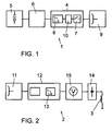
- the recommended electric power transmission system includes a transmitter module (1) and a receiver module (2) associated with a charge (3) for the purpose of supplying electric power in a controlled manner through the aforementioned transmitter module (1).
- the transmitter module (1) has a control circuit (4) supplied by one or more batteries (5) depending on the power required, that is, the amount of energy and the time it is to be applied to the charge, as well as the physical distance between the transmitter module (1) and the receiver (2) incorporating a converter (6) of continuous current to alternate current for supplying the control circuit (4) which, with the aid of a switch (7) and prior to filtering (8) supplies an electromagnetic transducer (9), such as a coil or similar, so that the current circulating through it induces a magnetic field, the frequency of which will depend on the signal generated by the control circuit (4).
- a control circuit (4) supplied by one or more batteries (5) depending on the power required, that is, the amount of energy and the time it is to be applied to the charge, as well as the physical distance between the transmitter module (1) and the receiver (2) incorporating a converter (6) of continuous current to alternate current for supplying the control circuit (4) which, with the aid of a switch (7) and prior to filtering (8) supplies an electromagnetic transducer (9), such as a coil
- control circuit (4) will incorporate a code generator (10) which codifies the signal induced in order to increase the degree of security in the system activation.
- the receiver module (2) also has an electromagnetic transducer (11) which, when it receives the magnetic flow generated by the transmitter module (1) induces a current at its outlet which, having adapted to the electronic control levels feeds a control circuit (12) which remained uncharged and therefore inactive, so that when the electronic control of the circuit (12) is activated it verifies that the induced signal is valid, and if so, by means of the induced current, prior to filtering (13-14) and adapting (15) to the required outlet voltage, it supplies electric power to the charge(3).
- an electromagnetic transducer (11) which, when it receives the magnetic flow generated by the transmitter module (1) induces a current at its outlet which, having adapted to the electronic control levels feeds a control circuit (12) which remained uncharged and therefore inactive, so that when the electronic control of the circuit (12) is activated it verifies that the induced signal is valid, and if so, by means of the induced current, prior to filtering (13-14) and adapting (15) to the required outlet voltage, it supplies electric power to
- the receiver module is a passive device which needs no maintenance it may be concealed beneath any kind of diamagnetic material, with such material barely interfering with the transmission of the magnetic flow, making it ideal for safety applications such as access locks to various premises.
- the transmitter module may be either a portable or fixed element depending on the application for which it is intended to.
Landscapes
- Engineering & Computer Science (AREA)
- Power Engineering (AREA)
- Computer Networks & Wireless Communication (AREA)
- Signal Processing (AREA)
- Lock And Its Accessories (AREA)
Priority Applications (1)
| Application Number | Priority Date | Filing Date | Title |
|---|---|---|---|
| EP06026982A EP1940043A1 (fr) | 2006-12-28 | 2006-12-28 | Système de transmission de puissance électrique dépourvu de conducteurs |
Applications Claiming Priority (1)
| Application Number | Priority Date | Filing Date | Title |
|---|---|---|---|
| EP06026982A EP1940043A1 (fr) | 2006-12-28 | 2006-12-28 | Système de transmission de puissance électrique dépourvu de conducteurs |
Publications (1)
| Publication Number | Publication Date |
|---|---|
| EP1940043A1 true EP1940043A1 (fr) | 2008-07-02 |
Family
ID=38115506
Family Applications (1)
| Application Number | Title | Priority Date | Filing Date |
|---|---|---|---|
| EP06026982A Withdrawn EP1940043A1 (fr) | 2006-12-28 | 2006-12-28 | Système de transmission de puissance électrique dépourvu de conducteurs |
Country Status (1)
| Country | Link |
|---|---|
| EP (1) | EP1940043A1 (fr) |
Citations (2)
| Publication number | Priority date | Publication date | Assignee | Title |
|---|---|---|---|---|
| EP1598951A1 (fr) * | 2004-05-10 | 2005-11-23 | Schneider Electric Industries SAS | Système de détection inductif de sécurité |
| WO2006016149A1 (fr) * | 2004-08-10 | 2006-02-16 | Instrumental Limited | Commande d'actionnement |
-
2006
- 2006-12-28 EP EP06026982A patent/EP1940043A1/fr not_active Withdrawn
Patent Citations (2)
| Publication number | Priority date | Publication date | Assignee | Title |
|---|---|---|---|---|
| EP1598951A1 (fr) * | 2004-05-10 | 2005-11-23 | Schneider Electric Industries SAS | Système de détection inductif de sécurité |
| WO2006016149A1 (fr) * | 2004-08-10 | 2006-02-16 | Instrumental Limited | Commande d'actionnement |
Similar Documents
| Publication | Publication Date | Title |
|---|---|---|
| US7111817B2 (en) | Municipal water delivery control systems | |
| US6243000B1 (en) | Wireless rolling code security system | |
| JP4824250B2 (ja) | エネルギー自給式高周波送信器 | |
| US8276877B2 (en) | Solenoid valve controlled by wireless communication | |
| US4355309A (en) | Radio frequency controlled light system | |
| US20070008126A1 (en) | Integrated security system and method | |
| FR2839392B1 (fr) | Dispositif de transmission de rayonnement electromagnetique a travers une paroi | |
| CN103581908B (zh) | 用于车辆中的双范围探测的装置和方法 | |
| WO2009023965A1 (fr) | Appareils interactif, systèmes d'appareils et procédés de commande d'appareils, et commandes associées | |
| CN110140155B (zh) | 多频设备、控制和/或监视设备、相关的多频系统和住宅自动化设施 | |
| CN101644953A (zh) | 用于安全系统的小键盘 | |
| US20070035382A1 (en) | Radio frequency identification (RFID) device with multiple identifiers and a control input | |
| CN205301842U (zh) | 一种智能家居用冰箱 | |
| CN103430221A (zh) | 用于锁定/解锁机动车辆的可移动面板的电子通信模块、相关控制中央处理单元和免伸手访问系统 | |
| KR101117664B1 (ko) | 무선 및 터치 겸용 조명스위치장치 | |
| US9685014B1 (en) | Remote control system using different types of carrier waves for polling signals | |
| US20080084120A1 (en) | Electric power transmission system without conductors | |
| CN101272650A (zh) | 热射线无线发送机和无线接收机 | |
| EP1940043A1 (fr) | Système de transmission de puissance électrique dépourvu de conducteurs | |
| CN201812348U (zh) | 一种防盗报警系统及带防盗报警功能的装饰板材 | |
| Kanagamalliga et al. | A ZigBee and embedded based security monitoring and control system | |
| US20180286198A1 (en) | Occupancy-sensor wireless-security and lighting-control | |
| US4484183A (en) | Method and system for detection of the presence, removal, or absence of a metal body | |
| KR102016352B1 (ko) | 전력선 도난 방지 장치 | |
| CN101272649A (zh) | 热射线无线发送机 |
Legal Events
| Date | Code | Title | Description |
|---|---|---|---|
| PUAI | Public reference made under article 153(3) epc to a published international application that has entered the european phase |
Free format text: ORIGINAL CODE: 0009012 |
|
| 17P | Request for examination filed |
Effective date: 20061228 |
|
| AK | Designated contracting states |
Kind code of ref document: A1 Designated state(s): AT BE BG CH CY CZ DE DK EE ES FI FR GB GR HU IE IS IT LI LT LU LV MC NL PL PT RO SE SI SK TR |
|
| AX | Request for extension of the european patent |
Extension state: AL BA HR MK RS |
|
| AKX | Designation fees paid |
Designated state(s): AT BE BG CH CY CZ DE DK EE ES FI FR GB GR HU IE IS IT LI LT LU LV MC NL PL PT RO SE SI SK TR |
|
| STAA | Information on the status of an ep patent application or granted ep patent |
Free format text: STATUS: THE APPLICATION IS DEEMED TO BE WITHDRAWN |
|
| 18D | Application deemed to be withdrawn |
Effective date: 20090106 |