EP1940104A2 - Dispositif et procédé destinés à la décision d'un symbole lors de la réception d'un un signal couplé à une paire de signaux de quadrature en vue du réglage de fréquence QAM et/ou du réglage de rotation - Google Patents
Dispositif et procédé destinés à la décision d'un symbole lors de la réception d'un un signal couplé à une paire de signaux de quadrature en vue du réglage de fréquence QAM et/ou du réglage de rotation Download PDFInfo
- Publication number
- EP1940104A2 EP1940104A2 EP07025152A EP07025152A EP1940104A2 EP 1940104 A2 EP1940104 A2 EP 1940104A2 EP 07025152 A EP07025152 A EP 07025152A EP 07025152 A EP07025152 A EP 07025152A EP 1940104 A2 EP1940104 A2 EP 1940104A2
- Authority
- EP
- European Patent Office
- Prior art keywords
- weighting
- symbol
- control
- signal
- value
- Prior art date
- Legal status (The legal status is an assumption and is not a legal conclusion. Google has not performed a legal analysis and makes no representation as to the accuracy of the status listed.)
- Withdrawn
Links
- 238000000034 method Methods 0.000 title claims abstract description 21
- 230000003111 delayed effect Effects 0.000 claims description 6
- 238000005070 sampling Methods 0.000 description 20
- 238000006243 chemical reaction Methods 0.000 description 8
- 230000006870 function Effects 0.000 description 6
- 230000001419 dependent effect Effects 0.000 description 4
- 238000004364 calculation method Methods 0.000 description 3
- 230000002452 interceptive effect Effects 0.000 description 3
- 239000000969 carrier Substances 0.000 description 2
- 239000000284 extract Substances 0.000 description 2
- 238000001914 filtration Methods 0.000 description 2
- 238000011084 recovery Methods 0.000 description 2
- 230000002123 temporal effect Effects 0.000 description 2
- 230000003044 adaptive effect Effects 0.000 description 1
- 230000003321 amplification Effects 0.000 description 1
- 230000005540 biological transmission Effects 0.000 description 1
- 230000001276 controlling effect Effects 0.000 description 1
- 238000010586 diagram Methods 0.000 description 1
- 230000005484 gravity Effects 0.000 description 1
- 239000000203 mixture Substances 0.000 description 1
- 230000007935 neutral effect Effects 0.000 description 1
- 238000003199 nucleic acid amplification method Methods 0.000 description 1
- 230000001105 regulatory effect Effects 0.000 description 1
- 230000003252 repetitive effect Effects 0.000 description 1
- 238000007619 statistical method Methods 0.000 description 1
Images


Classifications
-
- H—ELECTRICITY
- H04—ELECTRIC COMMUNICATION TECHNIQUE
- H04L—TRANSMISSION OF DIGITAL INFORMATION, e.g. TELEGRAPHIC COMMUNICATION
- H04L27/00—Modulated-carrier systems
- H04L27/32—Carrier systems characterised by combinations of two or more of the types covered by groups H04L27/02, H04L27/10, H04L27/18 or H04L27/26
- H04L27/34—Amplitude- and phase-modulated carrier systems, e.g. quadrature-amplitude modulated carrier systems
- H04L27/38—Demodulator circuits; Receiver circuits
-
- G—PHYSICS
- G05—CONTROLLING; REGULATING
- G05D—SYSTEMS FOR CONTROLLING OR REGULATING NON-ELECTRIC VARIABLES
- G05D17/00—Control of torque; Control of mechanical power
- G05D17/02—Control of torque; Control of mechanical power characterised by the use of electric means
-
- H—ELECTRICITY
- H04—ELECTRIC COMMUNICATION TECHNIQUE
- H04L—TRANSMISSION OF DIGITAL INFORMATION, e.g. TELEGRAPHIC COMMUNICATION
- H04L27/00—Modulated-carrier systems
- H04L27/0014—Carrier regulation
- H04L2027/0024—Carrier regulation at the receiver end
- H04L2027/0026—Correction of carrier offset
- H04L2027/003—Correction of carrier offset at baseband only
-
- H—ELECTRICITY
- H04—ELECTRIC COMMUNICATION TECHNIQUE
- H04L—TRANSMISSION OF DIGITAL INFORMATION, e.g. TELEGRAPHIC COMMUNICATION
- H04L27/00—Modulated-carrier systems
- H04L27/0014—Carrier regulation
- H04L2027/0044—Control loops for carrier regulation
- H04L2027/0053—Closed loops
- H04L2027/0055—Closed loops single phase
Definitions
- the invention relates to a device for QAM frequency control with the above-conceptual features according to claim 1 and a corresponding method for QAM frequency control.
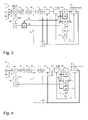
- a demodulator 1 for determining and deciding symbols D from a digitized signal sd which is connected to a quadrature signal pair of a modulation method, for. B. according to a QAM standard, is coupled from a plurality of individual components.
- the demodulator 1 receives an analog signal sa at an input from a signal source.
- This analog signal sa is supplied to an AD converter 2 for conversion to a digital signal sd.
- the AD converter 2 has an input for a sampling signal t.
- the digital signal sd is fed from the AD converter 2 to a quadrature converter 3.
- the quadrature converter 3 converts the digital signal sd into the baseband and outputs the digitized signal sd split into the two quadrature signal components of the Cartesian coordinate system.
- For frequency conversion of the quadrature converter 3 is fed with two offset by 90 ° carriers from a local oscillator 15 whose frequency and phase is controlled by a carrier control device 14.
- the quadrature signal components from the quadrature converter 3 are supplied to a gain controller 4.
- An output signal of the gain control device 4 is fed to a filter 5.
- the Both quadrature signal components I, Q are then fed to a symbol scanner 6, which has a sampling controller. The control of the symbol scanner 6 via an input to which a sampling signal t i is supplied.
- the symbol scanner 6 performs a temporal interpolation between the real samples on the symbol rate or an integer multiple thereof.
- the AD converter can be controlled with the sampling signal.
- the digital signal would already be at the symbol rate or a multiple thereof and the scanner could be eliminated.
- the output signal of the sampling device 6 is filtered by means of a particular Nyquist filter 7 and fed to an equalizer 8.
- the equalizer 8 provides a preliminary symbol at its output.
- decided symbols D are formed by means of the symbol decision maker 10. These symbols D are then supplied to further digital signal processing devices. The decision maker 10 thus extracts the digital data.
- This decision maker 10 is involved in the decision-feedback control of carrier frequency / phase, sampling time or equalizer.
- the clock controller 13 generates the sampling signal t i , which in particular the symbol scanner 6 or in the alternative embodiment, the AD converter is supplied.
- the clock control means 13 the signal of the equalizer 8 is supplied.
- the carrier control device 14 is applied a phase difference or a phase offset ⁇ , which is determined in a rotation control device 12.
- the phase offset ⁇ is determined between the phase ⁇ of the symbols before the decider 10 and the phase ⁇ d of the symbols D behind the decider 10.
- Such device and method for QAM frequency control with decision makers are for example DE 36 19 744 or DE 103 44 756 known.
- phase offset ⁇ is the angular difference between the sampled and digitized received signal and the decided symbol of the alphabet. Frequency offset causes a constant change of correctly determined phase offsets and can be measured as the difference of successive phase offsets.
- a conventional QAM receiver mixes by means of eg a circuit according to Fig. 9 the signal on a carrier frequency into the baseband and samples it at the symbol instants, whereupon a decision takes place after level matching, Nyquist filtering and adaptive filtering in an equalizer. It does not matter in which order the function blocks blend into baseband, sample with symbol rate and gain control.
- the mixing into the baseband can take place in the analog range before the then complex, ie two-channel A / D conversion or after the A / D conversion of the intermediate frequency, the sampling at symbol times, as described as an alternative, already by the A / D Converter or, if it works asynchronously on any frequency, through a digital sample rate conversion take place and blocks for gain control can be inserted at any point in principle.
- the local oscillator control must also control the carrier phase.
- the carrier phase is adjusted by an extra rotation with a rotation control signal, which is an estimated angle, in the form of a complex multiplication immediately before the decider, before the symbol decision takes place.
- a rotation control signal which is an estimated angle, in the form of a complex multiplication immediately before the decider, before the symbol decision takes place.
- the decided symbol D must be rotated back by the angle of the rotation control signal. If the estimated angle does not correspond to the actual rotation angle of the coordinate system of the received signal, a phase offset ⁇ results between the phase angle of the received signal and the angle of the decided symbol.
- the estimated rotation angle for the coming symbol decision comes from a phase offset filter. In the simplest case, it is a summer that adds the phase offset ⁇ to the current rotation angle.
- phase offset ⁇ indicates a frequency offset of the local oscillator and can therefore be used for its regulation.
- the phase offset ⁇ is low-pass filtered in a frequency control block.
- phase offset ⁇ does not always represent a frequency offset.
- the object of the invention is to provide a device with the above-conceptual features according to claim 1 and a corresponding method, which with simple Means allow an alternative QAM frequency control and / or rotation control.
- a device for deciding a symbol when receiving a signal coupled to a quadrature signal pair with a decider for deciding the symbol by analyzing a received signal in the complex coordinate space and with a control loop for QAM frequency control and / or rotation control using control parameters is formed and / or controlled depending on at least one decided by the decision maker to adjust the control parameters for later decisions, wherein a weighting device is formed and / or controlled, depending on the decider to be decided and / or decided symbols each have a weighting value of a plurality of weighting values from the symbol position in the complex coordinate space for the control loop.
- the weighting with weighting values depends on the concrete positions of decided or decisive symbols.
- the weighting means is preferably designed and / or controlled to provide the weighting value from a phase offset and / or rotation control signal.
- a weighting device is preferably designed and / or controlled with the weighting value to weight a control value for a carrier control device, in particular the phase offset, with the weighting value.
- the weighting values may thus be used in the manner of quality numbers to weight the phase offset in a frequency offset quality block, that the frequency control of the local oscillator already works during the acquisition phase of the circuit arrangement, in which there are still many wrong decisions.
- An alternative weighting device is preferably designed and / or controlled as part of a rotation control device, with the weighting value to weight a phase offset.
- the weighting value is thus used to improve the calculation of an estimated rotation signal as a rotation angle for an upcoming symbol decision.
- the weighting device can optionally provide an additional weighting value with which the control value, in particular a phase offset, for the carrier control device is additionally weighted as a delayed further weighting value.
- a delayed further weighting value in addition to the weighting value can be provided.
- the further weighting value device can in particular be designed as part of a phase offset filter.
- the weighting means is preferably designed and / or controlled to associate each symbol with the weighting value of the plurality of weighting values depending on its radius of the symbol in the complex coordinate space.
- the weighting means is preferably designed and / or controlled to individually associate with each symbol the weighting value of the plurality of weighting values depending on the position of the symbol in the complex coordinate space.
- weighting values can be provided in a simple manner.
- the weighting values can be provided in particular from the table as a two-dimensional or multidimensional table.
- a method for deciding a symbol when receiving a signal coupled to a pair of quadrature signals for QAM frequency control and / or rotation control in which a decision of a symbol is made with the aid of control parameters in the complex coordinate space with one decision maker and depending on at least one decided one is particularly preferred Symbol
- the control parameters are adapted for later decisions, wherein for the decider to be decided and / or decided symbols each have a weighting value of a plurality of weighting values is provided depending on the symbol position in the complex coordinate space for the control loop.
- a phase offset and / or a rotation control signal is preferably weighted.
- the plurality of weighting values may be provided in a table providing different pluralities of weighting values for each of the various symbol alphabets.
- the weighting values may be provided in a table, wherein the weighting values may be adjusted to a synchronization progress of the frequency control.
- a phase offset and / or a rotation value may also be weighted with two or more weight values.
- Such a method or circuit can be used in particular for complex digital modulation methods such as QAM. They are used by most new broadcast, television and data services over cable and z. T. also used terrestrial.
- symbols D of a symbol alphabet in the complex phase space I, Q are arranged in a manner known per se on radii r1-r9, a first quadrant with both axes in the positive region being considered for 64-QAM.
- the symbols D and the possible symbol radii r1-r9 in the first quadrant are shown.
- the symbols D are decided in a decider. Symbol values before and after the decider are fed to the control loop as basic quantities for determining control parameters.
- control parameters or intermediate values used to determine them are weighted with weighting values G. This does not apply to all control parameters, in part only for the phase ⁇ or the angle ⁇ .
- Each radius r1-r9 and / or each symbol D is assigned a quality number or its own weighting value G.
- weighting values G are respectively assigned to the respective radii r1-r9 in a simple embodiment.
- radii r2, r4, r6 which are close to others of the radii r3, r5, r7 are assigned low weighting values or the value "0" because symbols on them are low weighted radii r2, r4, r6 can lead to particularly erroneous decisions.
- radii r1, r3, r8, r9 which are remote from others of the radii r2, r4, r6 or otherwise can lead to particularly safe decisions are assigned high weighting values "2", "3", "4".
- each symbol D of the alphabet is assigned a quality number or a weighting value G, which is a measure of the probable correctness of the decision.
- This quality number is based on the purpose of its use, here e.g. the probable correctness of a measured phase offset.
- symbols D are located in the corners of the constellation as well as on radii whose neighboring radii are far away, especially on those radii which have only one symbol on the bisector of the square or at least no symbols near the I and Q axes , prefers. This is, especially in a decision initially for radii, as taken for example from DE 36 19 744 is known, or when deciding how to take it off DE 103 44 756 is known, a much better frequency control possible.
- Such radii ri or symbols D with high numbers are more immune to offsets of the carrier phase and therefore more meaningful when a large frequency or phase offset of the carrier is still to be expected. This is the case in particular, if not the conventional rectangular decision is used, but such after eg DE 103 44 756 in which the radii can be strongly favored over the angles.
- the quality numbers are obtained by a statistical analysis of possible errors by offsets in the carrier phase and in the sampling phase.
- the quality numbers can also be variable and adapted to the progress of the signal acquisition.
- the weighting values G can also be determined individually for the individual symbols D independently of the assignment to fixed radii ri. Particular preference is given to an assignment according to radii ri and positions n within the radii ri, so that the weighting values G (D (ri, n)) are assigned as a function of the individual symbols D and the radii ri.
- a demodulator 1 is an exemplary circuit arrangement for determining and deciding symbols D from a digitized signal sd, which is connected to a quadrature signal pair of a modulation method, z. B. according to a QAM standard, is coupled from a plurality of individual components. These can all or individually also be part of an integrated circuit. In particular, components described below can be omitted depending on the intended use, interchangeable with one another in the sequence or can be supplemented by further components. Also, the continuation of signals as real signals, complex signals or individual complex signal components depending on the application and special circuit arrangement can be implemented accordingly.
- the demodulator 1 receives an analog signal sa at an input from a signal source, such as a tuner.
- This analog signal sa which is usually present in a band-limited intermediate frequency position, is transmitted to an AD converter 2 (AD: analogue / digital) supplied for conversion into a digital signal sd.
- AD converter 2 has an input for a clock signal or sampling signal t.
- the digital signal sd is fed from the AD converter 2 to a mixer or quadrature converter 3.
- the quadrature converter 3 converts the digital or digitized signal sd into baseband.
- the baseband corresponds to the requirements of the demodulator 1 and the modulation method used. Accordingly, the quadrature converter outputs the digitized signal sd split into the two quadrature signal components I, Q of the Cartesian coordinate system.
- the quadrature converter 3 is usually supplied with two carriers offset by 90 ° from a local oscillator 15 whose frequency and phase are controlled by a carrier control device 14.
- the carrier control device 14 is designed in particular as a frequency control device.
- the quadrature signal components I, Q output from the quadrature converter 3 are supplied to a gain controller 4.
- the control of the gain control device 4 is used to optimally exploit the Aus Kunststoff Kunststoff a Symbolentscheiders 10.
- An output signal of the gain control device 4 is fed, for example, to a bandpass filter or a low-pass filter 5, which frees the digital signal from DC components or interfering harmonics.
- the quadrature signal components I, Q are supplied before or after amplification by the gain control device 4 to a low-pass filter 5, which serves to eliminate interfering harmonics.
- the thus amplified and filtered quadrature signal pair I, Q and the two quadrature signal components I, Q are then fed to a symbol scanner 6, which has a Abtastregel Surprise.
- the control of the symbol scanner 6 via an input to which a sampling signal t i is supplied.
- the symbol sampling instants of the sampling signal t i are oriented in the normal operating state on the symbol rate 1 / T and usually also on the exact phase of the received digital signal sd.
- the symbol sampling device 6 performs a temporal interpolation between the real samples on the symbol rate or an integer multiple of it. Alternatively, for example, symbols may already be determined in connection with the sampling of the AD converter.
- the output signal of the sampling device 6 is filtered by means of a particular low-pass filter 7 with a Nyquist characteristic and fed to an equalizer (equalizer) 8.
- the equalizer 8 frees the two components of the quadrature signal pair I, Q of interfering distortions and provides a preliminary symbol at its output.
- the complex-valued received signal waiting after the equalizer 8 is thus fed, as usual, to a symbol decider 10 which extracts the digital data.
- this decision maker 10 is integrated into the decision feedback control of carrier frequency / phase (carrier / phase recovery), sampling time (timing, clock recovery) or equalizer (equalizer).
- the signal output by the equalizer 8 is supplied to an array of components (12-22) for determining control parameters, which may be wholly or partly integral. These control parameters are then fed directly or indirectly to the decision-feedback control circuits or components in the demodulator 1.
- the equalizer 8, the gain control device 4, the carrier control device 14 and the symbol scanner 6 are supplied with the symbols S or the symbol components R, ⁇ or other signals generated therefrom, eg the sampling signal t i supplied according to circuitry with both quadrature signal components I, Q of the symbol S in Cartesian coordinates or in polar coordinates.
- the supply of individual components with only one of the quadrature signal components for example, the carrier control device 14, with the angle or the phase ⁇ in polar coordinates and the gain control device 4 with the radius or amplitude information R in polar coordinates.
- ⁇ is a coordinate converter, which receives the provisional symbol or, if necessary, also the decided symbol D.
- the arrangement for determining the control parameters consists of a rotation device 9, which as a possible form of such a coordinate converter rotates the signal output by the equalizer 8 by a certain amount.
- a rotation control signal ⁇ ' is supplied.
- the rotation control signal ⁇ ' corresponds to an estimated instantaneous tilt angle between the received coordinate system of the received one
- the rotation control signal ⁇ ' is determined in a rotation control device 12, 16, to which the output signal of the rotation device 9 and the output signal of the regulating decider 10 are supplied.
- the decision maker 10 also receives the output signal of the rotation device 9.
- the output signal of the decider 10 is also fed to a counter-rotation device 11 for performing an opposite rotation.
- the counter-rotation device 11 is likewise supplied with the rotation control signal ⁇ 'to the rotation control device 12, 16.
- the output signal of the counter-rotation device 11 is fed to a clock control device 13 and the equalizer 8.
- the clock controller 13 generates the sampling signal t i , which is supplied to the symbol scanner 6 or, in the alternative embodiment, to the AD converter 2.
- the clock control device 13 is supplied with a base clock of a clock source which is based on the symbol rate 1 / T and the symbol duration / symbol period T of the modulation method and the demodulator 1 used.
- the clock control means 13 the signal of the equalizer 8 is supplied.
- the carrier control device 14 is applied to a phase difference or a phase offset ⁇ , which is determined in a first stage 12 of the rotation control device 12, 16.
- the phase offset ⁇ is optionally determined as the difference between the phase ⁇ of the symbols before the decision maker 10 and the phase ⁇ d of the symbols D behind the decision maker 10.
- a rotation signal ⁇ is determined from the phase offset ⁇ and the rotation control signal ⁇ '.
- the rotation signal ⁇ is delayed by means of a delay element 17, z -1 and provided as the rotation control signal ⁇ '.
- control device 13 For controlling the clock control device 13 and further of the components of the demodulator 1, these are preferably connected to a control device.
- the controller causes proper operation and controls the individual components and operations in accordance with hard or software based instructions.
- the control device may also have functions of individual ones of said components completely or partially integrated in it.
- An essential element of all embodiments is a weight value device 18 for providing the weighting values G for the symbols D to be decided by the decision maker 10.
- the weighting value device 18 can receive from the decision maker 10 a symbol D to be used or used for the decision or as an integral part thereof Be educated decision maker. Also possible is a purely software-technical implementation.
- the weighting means 18 provides for the respective symbol D the weighting value G associated therewith or a time sequence of such weighting values G.
- This weighting value G is used for direct or indirect weighting of further parameters relevant to the control, in particular for weighting the phase offset ⁇ and / or the rotation control signal ⁇ '.
- the weighting value G of a first weighting device 19 is applied, which is connected between the first stage 12 of the rotation control device 12, 16 on the one hand and on the other hand the support control device 14.
- the phase offset ⁇ is weighted with the weighting value G in accordance with its output signal values.
- the weighting values G serving as quality numbers are thus determined simultaneously with the decided symbols D in an additional block to the decision maker 10.
- the quality numbers can thus be used to weight the phase offset ⁇ in the weighting device 19 or in the frequency offset quality block such that the frequency control of the local oscillator 15 already works during the acquisition phase of the demodulator 1, in which there are still many wrong decisions.
- the weighting is carried out by multiplying the phase offset ⁇ by the weighting value G, before this result is low-pass filtered in the frequency control block.
- the weighting value G is applied in accordance with a second exemplary embodiment of a second weighting device 16, which is integrated in the rotation control device 12, 16.
- the second weighting device 16 is formed by the second stage 16 of the rotation control device 12, 16.
- a weighting with the weighting value G is additionally performed to provide the rotation signal ⁇ .
- the quality number G is used to improve the calculation of the estimated rotation signal ⁇ as a rotation angle for the upcoming symbol decision.
- the simplest form of influencing is multiplication, wherein the statistical mean of the weighting values G should preferably be around 1.
- the calculation of the estimated rotation signal ⁇ by the weighting value G in the phase offset filter is influenced.
- the weighting value G is applied according to a third embodiment of first and second weighting means 19 and 16, respectively.
- the first weighting device 19 is, as in Fig. 3 , between the first stage 12 of the rotation control device 12, 16 on the one hand and on the other hand, the carrier control device 14 connected.
- the second weighting device 16 is, as in FIG Fig. 4 , integrated in the rotation control device 12, 16.
- the second weighting device 16 is again formed by the second stage 16 of the rotation control device 12, 16.
- the second weighting device 16 optionally additionally provides a further weighting value H, which is additionally applied to the first weighting device 19 by means of a further delay element 23, z -1 as a delayed further weighting value H '.
- the first weighting device 19 thus weights the phase offset ⁇ with two weighting values G, H '.
- the quality of the decision for a symbol D and thus for a phase offset ⁇ is not only the geometric position of the current signal and thus the decided symbol D. but also on the quality of the rotation angle or rotation control signal ⁇ ', which has rotated the input signal into the coordinate system of the decider 10. Therefore, according to this embodiment, not only the quality G of the decided symbol but also the quality H 'of the current coordinate rotation in the form of the current rotation control signal ⁇ ' is taken into consideration.
- the quality G or the weighting value H of the rotation is derived from the quality of the symbol decision in a function of the phase offset filter.
- This function can be analogous to the function with which the next coordinate rotation, z. B. as a low-pass filter or median filter is calculated.
- a symbol quality in the form of the first weighting value G and a current rotation quality in the form of the second weighting value H 'in the frequency offset quality block are used to weight the phase offset ⁇ .
- the weighting value G is applied according to a fourth exemplary embodiment of a first weighting device 19.
- the first weighting device 19 is, as in Fig. 3 , between the first stage 12 of the rotation control device 12, 16 on the one hand and on the other hand, the carrier control device 14 connected.
- the first weighting device 19 thus weights the phase offset ⁇ similarly as in FIG Fig. 4 , again with two weights G, H '.
- phase quality in the form of the first weighting value G as the quality or second weighting value H of the rotation of the coordinate system.
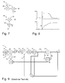
- Fig. 7 shows two exemplary circuits for converting the first weighting device 19 in a frequency offset quality block.
- the two pieces of information, symbol quality as the first weighting value G and current grade of rotation as the second weighting value H ', are used in the frequency quality block to weight the phase offset ⁇ .
- a simple arrangement consists in that the phase offset ⁇ is multiplied by means of two multipliers 20, 21 with both grades or weighting values G, H '. According to the other arrangement, the two grades G, H 'are added in an adder 22. Subsequently, the phase offset ⁇ is multiplied by the sum of the adder 22 in a multiplier 20.
- Other mathematical operations can be used.
- the quality table may be a memory element of the weighting means 18 or connected to it.
- the quality table is used for each symbol alphabet used, e.g. 256-QAM, 64-QAM.
- the quality numbers or weighting values G, H 'need not be constants, but the quality table can preferably be adapted to the progress of the synchronization.
- neutral elements in particular as a factor of "1" can be written in such a table so as to neutralize the circuit.
- Symbols D or radii r which should not be taken into account in the control, have a quality number of "0", as for example Fig. 1 and 2 is apparent.
- Fig. 8 shows in the upper curve the measured and accumulated absolute phase error and in the lower curve the accumulator of the frequency control.
- a frequency offset of, for example, 0.1 ⁇ f symbol is switched on with f symbol as the symbol frequency.
Landscapes
- Engineering & Computer Science (AREA)
- Physics & Mathematics (AREA)
- General Physics & Mathematics (AREA)
- Automation & Control Theory (AREA)
- Computer Networks & Wireless Communication (AREA)
- Signal Processing (AREA)
- Digital Transmission Methods That Use Modulated Carrier Waves (AREA)
Applications Claiming Priority (1)
| Application Number | Priority Date | Filing Date | Title |
|---|---|---|---|
| DE102006062519A DE102006062519A1 (de) | 2006-12-29 | 2006-12-29 | Vorrichtung und Verfahren zum Entscheiden eines Symbols beim Empfang eines mit einem Quadratursignalpaar gekoppelten Signals zur QAM-Frequenzregelung und/oder Rotationsregelung |
Publications (2)
| Publication Number | Publication Date |
|---|---|
| EP1940104A2 true EP1940104A2 (fr) | 2008-07-02 |
| EP1940104A3 EP1940104A3 (fr) | 2012-07-25 |
Family
ID=39273061
Family Applications (1)
| Application Number | Title | Priority Date | Filing Date |
|---|---|---|---|
| EP07025152A Withdrawn EP1940104A3 (fr) | 2006-12-29 | 2007-12-27 | Dispositif et procédé destinés à la décision d'un symbole lors de la réception d'un un signal couplé à une paire de signaux de quadrature en vue du réglage de fréquence QAM et/ou du réglage de rotation |
Country Status (3)
| Country | Link |
|---|---|
| US (1) | US8774323B2 (fr) |
| EP (1) | EP1940104A3 (fr) |
| DE (1) | DE102006062519A1 (fr) |
Families Citing this family (1)
| Publication number | Priority date | Publication date | Assignee | Title |
|---|---|---|---|---|
| DE10344756A1 (de) * | 2003-09-25 | 2005-05-12 | Micronas Gmbh | Verfahren und Schaltungsanordnung zum Entscheiden eines Symbols im komplexen Phasenraum eines Quadraturmodulationsverfahrens |
Citations (5)
| Publication number | Priority date | Publication date | Assignee | Title |
|---|---|---|---|---|
| DE3619744A1 (de) | 1986-06-12 | 1987-12-17 | Ant Nachrichtentech | Verfahren zum gewinnen eines phasendifferenzsignals |
| US5471508A (en) | 1993-08-20 | 1995-11-28 | Hitachi America, Ltd. | Carrier recovery system using acquisition and tracking modes and automatic carrier-to-noise estimation |
| US5799037A (en) | 1996-02-16 | 1998-08-25 | David Sarnoff Research Center Inc. | Receiver capable of demodulating multiple digital modulation formats |
| DE10344756A1 (de) | 2003-09-25 | 2005-05-12 | Micronas Gmbh | Verfahren und Schaltungsanordnung zum Entscheiden eines Symbols im komplexen Phasenraum eines Quadraturmodulationsverfahrens |
| DE10347259A1 (de) | 2003-10-08 | 2005-05-12 | Micronas Gmbh | Verfahren zum Synchronisieren einer Schaltungsanordnung beim Empfang eines modulierten Signals |
Family Cites Families (10)
| Publication number | Priority date | Publication date | Assignee | Title |
|---|---|---|---|---|
| FR2542536B1 (fr) * | 1983-03-07 | 1985-07-12 | Trt Telecom Radio Electr | Dispositif de recuperation de la porteuse d'un signal d'entree module par sauts d'amplitude et par sauts de phase |
| FR2581277A1 (fr) * | 1985-04-30 | 1986-10-31 | Labo Electronique Physique | Circuit de recuperation de l'onde porteuse de systemes de transmissions numeriques |
| WO1987001535A1 (fr) * | 1985-08-30 | 1987-03-12 | Fujitsu Limited | Systeme de transmission des donnees par radio |
| EP0281652B1 (fr) * | 1987-03-10 | 1990-12-05 | ANT Nachrichtentechnik GmbH | Procédé d'obtention d'un signal de différence de phase |
| FR2621188B1 (fr) * | 1987-09-25 | 1989-12-29 | Labo Electronique Physique | Circuit de recuperation de l'onde porteuse de systemes de transmissions numeriques |
| DE59709234D1 (de) * | 1997-07-31 | 2003-03-06 | Micronas Semiconductor Holding | Trägerregelkreis für einen Empfänger von digital übertragenen Signalen |
| KR100348790B1 (ko) * | 1999-12-21 | 2002-08-17 | 엘지전자주식회사 | 큐에이엠 수신기 |
| DE10249492A1 (de) * | 2002-10-24 | 2004-05-13 | Micronas Gmbh | Verfahren und Schaltung zur Erzeugung eines Hilfssymbols zum Einregeln eines QAM-Demodulators |
| DE102004020300B3 (de) * | 2004-04-26 | 2005-09-22 | Micronas Gmbh | Verfahren und Schaltungsanordnung zum Bestimmen eines Taktsignal-Abtastzeitpunkts für Symbole eines Modulationsverfahrens |
| DE102004023889A1 (de) * | 2004-05-12 | 2005-12-08 | Micronas Gmbh | Verfahren und Schaltungsanordnung zum Bestimmen der Frequenz eines empfangenen Signals zum Demodulieren von empfangenen Symbolen |
-
2006
- 2006-12-29 DE DE102006062519A patent/DE102006062519A1/de not_active Withdrawn
-
2007
- 2007-12-27 EP EP07025152A patent/EP1940104A3/fr not_active Withdrawn
- 2007-12-28 US US12/006,092 patent/US8774323B2/en active Active
Patent Citations (5)
| Publication number | Priority date | Publication date | Assignee | Title |
|---|---|---|---|---|
| DE3619744A1 (de) | 1986-06-12 | 1987-12-17 | Ant Nachrichtentech | Verfahren zum gewinnen eines phasendifferenzsignals |
| US5471508A (en) | 1993-08-20 | 1995-11-28 | Hitachi America, Ltd. | Carrier recovery system using acquisition and tracking modes and automatic carrier-to-noise estimation |
| US5799037A (en) | 1996-02-16 | 1998-08-25 | David Sarnoff Research Center Inc. | Receiver capable of demodulating multiple digital modulation formats |
| DE10344756A1 (de) | 2003-09-25 | 2005-05-12 | Micronas Gmbh | Verfahren und Schaltungsanordnung zum Entscheiden eines Symbols im komplexen Phasenraum eines Quadraturmodulationsverfahrens |
| DE10347259A1 (de) | 2003-10-08 | 2005-05-12 | Micronas Gmbh | Verfahren zum Synchronisieren einer Schaltungsanordnung beim Empfang eines modulierten Signals |
Also Published As
| Publication number | Publication date |
|---|---|
| US20080225992A1 (en) | 2008-09-18 |
| DE102006062519A1 (de) | 2008-07-03 |
| US8774323B2 (en) | 2014-07-08 |
| EP1940104A3 (fr) | 2012-07-25 |
Similar Documents
| Publication | Publication Date | Title |
|---|---|---|
| EP0486554B1 (fr) | Procede et dispositif pour la conversion de signaux de reception a modulation numerique haute frequence | |
| DE19639237A1 (de) | Doppel-Fernsehtuner | |
| EP1592164B1 (fr) | Procédé et circuit pour déterminer un point d'échantillonnage par un signal d'horloge pour des symboles d'un procédé de modulation | |
| DE69932723T2 (de) | Nichtlineare Korrekturvorrichtung | |
| DE60131336T2 (de) | QAM-Empfänger mit Verstärkungsregelung, Korrektur von Gleichstromverschiebungen und Passbandentzerrung | |
| DE102004052897A1 (de) | Funkempfänger für den Empfang von mit zwei Modulationsarten modulierten Datenbursts | |
| DE102007056490A1 (de) | Verfahren und Schaltungsanordnung zum Entscheiden eines Symbols beim Empfang von mit einem Quadratursignalpaar gekoppelten empfangenen Symbolen | |
| EP1523146A2 (fr) | Procédé pour la synchonisation d'un circuit lors de la réception d'un signal modulé | |
| EP1641205B1 (fr) | Appareil et procédé pour la récupération de la porteuse | |
| DE4223121A1 (de) | Verfahren zur Trägerrückgewinnung bei der Demodulation von digital modulierten Signalen und Anordnungen zum Ausführen des Verfahrens | |
| EP1940104A2 (fr) | Dispositif et procédé destinés à la décision d'un symbole lors de la réception d'un un signal couplé à une paire de signaux de quadrature en vue du réglage de fréquence QAM et/ou du réglage de rotation | |
| DE102004047398B3 (de) | Gemeinsamer Detektor für Taktphase und Trägerphase | |
| EP1556986B1 (fr) | Procede et circuit pour generer un symbole auxiliaire pour le reglage d'un demodulateur maq | |
| DE10393730T5 (de) | Vorrichtung und Verfahren zur Ermittlung einer NTSC-Gleichkanalstörung | |
| EP1892910A2 (fr) | Procédé ou circuit destiné à déterminer un symbole lors de la réception d'un signal coupé avec une paire de signaux à quadrature | |
| WO2008116544A1 (fr) | Concept pour réduire un bruit de phase | |
| DE102004036464B4 (de) | Trägerphasendetektor | |
| DE102006005032A1 (de) | Empfangsverfahren mit digitaler Pegeleinstellung im Analogteil und stufenweiser Pegelveränderung im Digitalteil | |
| DE10036703B4 (de) | Verfahren und Vorrichtung zur Korrektur eines Resamplers | |
| DE10245687B4 (de) | Frequenzfehlerkorrektur in einem Übertragungssystem | |
| DE102010064614B3 (de) | Verfahren und Vorrichtung zum Modifizieren einer Charakteristik eines komplexwertigen Signals | |
| DE102004023889A1 (de) | Verfahren und Schaltungsanordnung zum Bestimmen der Frequenz eines empfangenen Signals zum Demodulieren von empfangenen Symbolen | |
| DE10324614A1 (de) | Frequenzmodulationssystem und zugehöriges Verfahren | |
| WO1997007612A1 (fr) | Procede de synchronisation | |
| DE69830428T2 (de) | Dekodierungsfehlerfreier diversitätsempfänger, sowie schaltung zur talzurückgewinnung für diversitätsempfänger |
Legal Events
| Date | Code | Title | Description |
|---|---|---|---|
| PUAI | Public reference made under article 153(3) epc to a published international application that has entered the european phase |
Free format text: ORIGINAL CODE: 0009012 |
|
| AK | Designated contracting states |
Kind code of ref document: A2 Designated state(s): AT BE BG CH CY CZ DE DK EE ES FI FR GB GR HU IE IS IT LI LT LU LV MC MT NL PL PT RO SE SI SK TR |
|
| AX | Request for extension of the european patent |
Extension state: AL BA HR MK RS |
|
| RAP1 | Party data changed (applicant data changed or rights of an application transferred) |
Owner name: TRIDENT MICROSYSTEMS (FAR EAST) LTD. |
|
| PUAL | Search report despatched |
Free format text: ORIGINAL CODE: 0009013 |
|
| AK | Designated contracting states |
Kind code of ref document: A3 Designated state(s): AT BE BG CH CY CZ DE DK EE ES FI FR GB GR HU IE IS IT LI LT LU LV MC MT NL PL PT RO SE SI SK TR |
|
| AX | Request for extension of the european patent |
Extension state: AL BA HR MK RS |
|
| RIC1 | Information provided on ipc code assigned before grant |
Ipc: H04L 27/38 20060101AFI20120620BHEP |
|
| RAP1 | Party data changed (applicant data changed or rights of an application transferred) |
Owner name: ENTROPIC COMMUNICATIONS, INC. |
|
| 17P | Request for examination filed |
Effective date: 20130124 |
|
| AKX | Designation fees paid |
Designated state(s): AT BE BG CH CY CZ DE DK EE ES FI FR GB GR HU IE IS IT LI LT LU LV MC MT NL PL PT RO SE SI SK TR |
|
| 17Q | First examination report despatched |
Effective date: 20140204 |
|
| R17C | First examination report despatched (corrected) |
Effective date: 20131126 |
|
| GRAP | Despatch of communication of intention to grant a patent |
Free format text: ORIGINAL CODE: EPIDOSNIGR1 |
|
| INTG | Intention to grant announced |
Effective date: 20140925 |
|
| STAA | Information on the status of an ep patent application or granted ep patent |
Free format text: STATUS: THE APPLICATION IS DEEMED TO BE WITHDRAWN |
|
| 18D | Application deemed to be withdrawn |
Effective date: 20150206 |