EP1940318B1 - Cristallin intraoculaire servant a corriger une coma corneenne - Google Patents
Cristallin intraoculaire servant a corriger une coma corneenne Download PDFInfo
- Publication number
- EP1940318B1 EP1940318B1 EP06806569.7A EP06806569A EP1940318B1 EP 1940318 B1 EP1940318 B1 EP 1940318B1 EP 06806569 A EP06806569 A EP 06806569A EP 1940318 B1 EP1940318 B1 EP 1940318B1
- Authority
- EP
- European Patent Office
- Prior art keywords
- lens
- cornea
- coma
- shape factor
- radius
- Prior art date
- Legal status (The legal status is an assumption and is not a legal conclusion. Google has not performed a legal analysis and makes no representation as to the accuracy of the status listed.)
- Active
Links
- 0 CC1=C*C*1 Chemical compound CC1=C*C*1 0.000 description 4
Images





Classifications
-
- A—HUMAN NECESSITIES
- A61—MEDICAL OR VETERINARY SCIENCE; HYGIENE
- A61B—DIAGNOSIS; SURGERY; IDENTIFICATION
- A61B3/00—Apparatus for testing the eyes; Instruments for examining the eyes
- A61B3/0016—Operational features thereof
- A61B3/0025—Operational features thereof characterised by electronic signal processing, e.g. eye models
-
- A—HUMAN NECESSITIES
- A61—MEDICAL OR VETERINARY SCIENCE; HYGIENE
- A61F—FILTERS IMPLANTABLE INTO BLOOD VESSELS; PROSTHESES; DEVICES PROVIDING PATENCY TO, OR PREVENTING COLLAPSING OF, TUBULAR STRUCTURES OF THE BODY, e.g. STENTS; ORTHOPAEDIC, NURSING OR CONTRACEPTIVE DEVICES; FOMENTATION; TREATMENT OR PROTECTION OF EYES OR EARS; BANDAGES, DRESSINGS OR ABSORBENT PADS; FIRST-AID KITS
- A61F2/00—Filters implantable into blood vessels; Prostheses, i.e. artificial substitutes or replacements for parts of the body; Appliances for connecting them with the body; Devices providing patency to, or preventing collapsing of, tubular structures of the body, e.g. stents
- A61F2/02—Prostheses implantable into the body
- A61F2/14—Eye parts, e.g. lenses or corneal implants; Artificial eyes
- A61F2/16—Intraocular lenses
- A61F2/1613—Intraocular lenses having special lens configurations, e.g. multipart lenses; having particular optical properties, e.g. pseudo-accommodative lenses, lenses having aberration corrections, diffractive lenses, lenses for variably absorbing electromagnetic radiation, lenses having variable focus
Definitions
- the present invention is directed to a lens having an optical power for implantation in an eye having a cornea, more particularly an intraocular lens, and even more particularly to an intraocular lens that corrects for the coma of the cornea, as well as to a method of specifying the anterior surface and the posterior surface of a lens for implantation in an eye of a subject having a cornea.
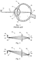
- FIG. 1 shows a cross-section of a human eye 10.
- light rays 11 originating from an object 12 enter the eye 10 through the cornea 13, pass through a liquid known as the aqueous humor 14, pass through the iris 15, pass through the lens 16, pass through another liquid known as the vitreous humor 17, and form an image 18 on the retina 19.
- the eye can suffer diseases that impair a patient's vision. For instance, a cataract may increase the opacity of the lens 16, causing blindness.
- the diseased lens may be surgically removed and replaced with an artificial lens, known as an intraocular lens, or IOL.
- IOL intraocular lens
- a patient whose natural lens has been removed is said to have aphakia, and one who surgically receives an artificial lens is said to have pseudophakic vision.
- FIGs. 2 and 3 show an example of aberration-free imaging, using a generic lens 21.
- the generic lens 21 is drawn as a simple two-surface lens, but is intended to represent the chain of optical elements in the eye, including the cornea 13 and the lens 16.
- An object 23 forms an image 24 on the retina 22.
- An on-axis bundle of rays 29 originating at the base 25 of the object 23 passes through the generic lens 21, and the rays strike the retina 22 at the base 27 of the image 24.
- an off-axis bundle of rays 31 originating at the edge 26 of the object 23 passes through the generic lens 21, and the rays strike the retina 22 at the edge 28 of the image 24.
- the visual acuity of the eye is directly related to the amount of aberration present in the eye's optical system, and any reduction in aberration is desirable.
- An intraocular lens is typically corrected for a single focus, meaning that objects at a particular position away from the eye appear in focus, while objects at an increasing distance away from that position appear increasingly blurred.
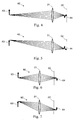
- FIGs. 4 through 7 This is illustrated in FIGs. 4 through 7 .
- a too-distant object 43 more distant from the generic lens 21 than object 23, forms an image 44 that is axially translated away from the retina 22 toward the lens 21.
- FIG. 4 shows an on-axis bundle of rays
- FIG. 5 shows an off-axis bundle of rays.
- the optical system 40 in FIGs. 4 and 5 shows a positive amount of defocus.
- a positive amount of defocus can occur even if the eye has its natural lens 16, if the range over which the natural lens 16 can accommodate is too small.
- this condition is known medically as myopia, or nearsightedness, and can be remedied by spectacles or a contact lens that introduces negative optical power into the eye's optical system, thereby increasing the effective focal length of the system and axially translating the image 44 back toward the retina 22.
- FIGs. 6 and 7 a too-close object 63, closer to the generic lens 21 than object 23, forms an image 64 that is axially translated away from the retina 22 away from the lens 21.
- the rays are drawn in FIGs. 6 and 7 as propagating beyond the retina to the image 64, in reality, the rays terminate at the retina 22 before forming an image.
- FIG. 6 shows an on-axis bundle of rays
- FIG. 7 shows an off-axis bundle of rays.
- the optical system 60 in FIGs. 6 and 7 shows a negative amount of defocus.
- a focal length is typically chosen to correct for relatively distant objects, and close objects appear as blurry without additional spectacles or contact lenses.
- an intraocular lens can reduce astigmatism in the eye.
- Astigmatism occurs when the optical power along one axis differs from the optical power along a different axis, leading to a rotationally asymmetric wavefront.
- the optical power along a vertical axis may be envisioned by blocking all the light in the pupil of the eye except a thin vertical slice through the center of the lens. Similar situations hold for a horizontal axis, or any other orientation between vertical and horizontal.
- the astigmatism may be corrected by adding a cylindrical component of power to the IOL along a particular axis, so that the wavefront that strikes the retina is essentially rotationally symmetric.
- the correction of astigmatism is well-known, and is straightforwardly accomplished in IOLs, as well as spectacles and some contact lenses.
- spherical aberration may be reduced.
- the optical power at the edge of the lens is different from the optical power at the center of the lens.
- a bundle of rays originating from a single point on the object, after passing through a lens with spherical aberration, does not converge to a single point on the image, but blurs by an amount in proportion to the amount of spherical aberration.
- FIG. 8 shows an optical system 80 with positive spherical aberration.
- FIG. 9 shows an optical system 90 with negative spherical aberration, in which the lens 91 has less optical power at its edge than at its center.
- spherical aberration is rotationally symmetric about the optical axis.
- Spherical aberration is also independent of field height or field angle, so that a bundle of rays originating from the edge of the object would exhibit the same amount of spherical aberration as a bundle originating from the base.
- U.S. Patent No. 6,609,793 discloses a method of designing an ophthalmic lens. First, at least one of the surfaces of the cornea is characterized as a mathematical model. Then, the model is used to calculate the aberrations of the surface or surfaces. Finally, the lens is modeled to reduce the aberrations for at least one of the foci, for an optical system that includes the lens and at least one of the surfaces of the cornea.
- the publication discloses reducing to essentially zero the eleventh Zernike coefficient, which corresponds to third-order spherical aberration. Additional correction is disclosed in U.S. Patent Application Serial No. 10/724,852 , and U.S. Patent No. 6,705,729 , .
- FIG. 10 a picture of an exemplary wavefront aberrated by coma is shown in FIG. 10 .
- an unaberrated wavefront 103 is shown, superimposed on the aberrated wavefront 104.
- the two wavefronts 103 and 104 coincide.
- the aberrated wavefront 104 shows an odd-order departure from the unaberrated wavefront 103.
- Third-order coma shows a cubic dependence in the wavefront departure along axis 101
- fifth-order coma shows a fifth- order dependence, and so forth for higher odd-orders of coma.
- the rays For a bundle of off-axis rays originating at a single point on the object, the rays converge to a cone-shaped blur at the image. Rays passing through the center of the aberrated lens arrive at the point of the cone, with the remainder of the bundle of rays filling out the characteristic cone shape.
- the orientation of the cone is radial with respect to the optical axis, and the size of the cone increases with distance away from the optical axis.
- the total amount of coma is generally fairly small.
- the cornea 13 and natural lens 16 may individually have substantial amounts of coma of opposite sign, which offset each other when light passes through both elements sequentially.
- the natural lens 16 is removed and replaced with an IOL, the coma of the cornea 13 may become significant, so that if the cornea's coma is not corrected by the IOL, it may degrade the vision of the eye.
- an intraocular lens that corrects for the coma of the cornea.
- an IOL reduces the amount of coma in the optical system of the eye (cornea and IOL together), and improves the vision of the eye.
- EP 1 424 049 A1 describes a method of designing a multifocal ophthalmic lens comprising the steps of: (i) characterizing at least one corneal surface as a mathematical model; (ii) calculating the resulting aberrations of set corneal surface(s) by employing said mathematical model; (iii) modelling the multifocal ophthalmic lens such that a wavefront arriving from an optical system comprising said lens and said at least one corneal surface obtains reduced aberrations for at least one of the foci.
- EP 1 262 815 A2 describes a method for designing and constructing of a spectacle lens for the correction of human vision.
- WO 02/088830 A1 describes a method for designing and making an ophthalmic lens, wherein the posterior surface of the customized contact lens is designed to accommodate the corneal topography of an eye.
- a method of specifying the anterior surface and the posterior surface of a lens for implantation in an eye having a cornea comprises: performing at least one measurement on the eye, on a model for the eye, or the eye and a model for the eye; determining an optical power from the at least one measurement; and determining an anterior radius and a posterior radius from the optical power, wherein the anterior radius and the posterior radius minimize the coma of the eye; and determining at least one aspheric term for at least one of the anterior surface and the posterior surface; whereby the coma of the lens offsets the coma of the cornea; and whereby the anterior surface and the posterior surface are specified by the anterior radius, the posterior radius and the at least one aspheric term.
- a further method of specifying the anterior surface and the posterior surface of a lens for implantation in the eye of a patient comprises: performing a measurement capable of determining an optical power, P, of the lens; determining a shape factor, X, from the optical power; determining an anterior radius, Ra, and a posterior radius, Rp, from the shape factor and the optical power; and determining at least one aspheric term for at least one of: the anterior surface and the posterior surface; whereby the anterior surface and the posterior surface are specified by the anterior radius, the posterior radius and the at least one aspheric term.
- An embodiment is an intraocular lens having an optical power and a shape factor, comprising: an anterior surface having an anterior radius; and a posterior surface having a posterior radius; wherein the anterior radius and the posterior radius determine the optical power and the shape factor; and wherein if the optical power P is between 0 diopters and 10 diopters, it has a shape factor X between -3 and - 1.6, or if the optical power P is between 5 diopters and 15 diopters, it has a shape factor X between -3 and -1.2, or if the optical power P is between 10 diopters and 20 diopters, it has a shape factor X between -1.9 and -0.8, or if the optical power P is between 15 diopters and 25 diopters, it has a shape factor X between -1.5 and - 0.5, or if the optical power P is between 20 diopters and 30 diopters, it has a shape factor X between -1.2 and -0.2, or if the optical power P is greater than 30 diopter
- a process is detailed below for designing an intraocular lens that reduces the coma of the eye's optical system, which gives better off-axis performance of the lens, as well as relaxed manufacturing and alignment tolerances.
- the process is broken into several general steps, some of which are given their own sections below. The steps may be performed in any order.
- a series of measurements are performed on the patient.
- the spherical radius of curvature of the anterior cornea is measured, or optionally the anterior and posterior corneal surfaces, as well as the axial length (i.e., the distance between the cornea and the retina).
- more measurements may be taken, or various other properties may be measured, such as a wavefront mapping of the cornea, axial length and anterior chamber depth.
- One goal of these patient measurements is to predict the required optical power of the intraocular lens.
- the measurements may also be performed on a model of the patient's eye.
- the model can be a physical model, or a virtual model generated by mathematical modeling as proposed by The Bioengineering Institute at the University of Auckland, New Zealand & McGill University in Montreal, Canada, or by 3D medical image visualization, such as 3DVIEWNIX, as proposed by the Medical Image Processing Group at the University of Pennsylvania, U.S.A..
- the measurements are used to predict the required power of the IOL.
- a thin-lens formalism is described that converts the measured values of axial length and corneal radius into a required optical power.
- a preferred shape factor X is determined that minimizes the coma of the total eye system.
- the shape factor X describes the base spherical radii of the lens surfaces independent of the power of the lens.
- the shape factor X attains its preferred value when the third-order coma of the lens best offsets the third-order coma of the cornea, and reduces the third-order coma of the total optical system of the eye.
- the formalism for determining the preferred shape factor X uses a paraxial model and/or a real raytracing model, and is described in detail in the section titled, "RAYTRACING MODEL". Once the model is established, the values of the preferred shape factor X are given in the section titled, "OPTIMAL LENS SHAPE FOR A GIVEN POWER".
- one or more aspheric and/or conic terms are added to one or both of the lens surfaces, so that spherical aberration is reduced and on-axis performance is improved.
- the adding of aspheres is detailed in the section titled, "OPTIMIZING AN INTRAOCULAR LENS DESIGN”. Designs for several values of power are carried to completion and are presented in the section titled, "SAMPLE DESIGNS”.
- This section describes an example of a known method (one of many known methods) of calculating the required power (or, equivalently, focal length) of an intraocular lens (IOL), based on a geometrical optics-based formula and several measured input values.
- IOL intraocular lens
- the calculations are performed using a paraxial raytrace, with four surfaces: (1) spectacles, (2) the cornea, (3) the intraocular lens, and (4) the retina.
- each of these four surfaces is assumed to be an infinitely thin surface or thin lens having a particular power.
- the numerical values used in the calculations may vary depending on the preference of the practitioner, but the thin lens methodology remains essentially unchanged. Each of these surfaces is described in more detail below.
- the refractive indices are dimensionless, the ray angles are in radians, the ray heights are in mm [or, alternately, m], and the surface powers are in mm -1 [or, alternately, diopters].
- the ray angle is in radians and the ray heights and distances are both in mm [or, alternately, both in m].
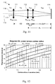
- FIG. 11 shows a schematic drawing of the thin lens system 110 used for predicting the required power of an intraocular lens.
- Rays originate at a distant object (not shown), pass through the spectacles 111, the cornea 112, the intraocular lens 113, and strike the retina 114.
- optical elements 111-113 are assumed to be rotationally symmetric about the optical axis 115.
- the equations should be used to trace a marginal ray 116 through the system, as follows.
- An object is assumed to be at infinity, so a marginal ray 116 originating at the base of the object arrives at the spectacles 111 with a ray angle u of 0 and a non-zero ray height y (with a value typically proportional to the pupil diameter, but unimportant for predicting the required intraocular lens power).
- This marginal ray 116 is then traced from the object at infinity in refractive index n air , through the spectacles 111 with power ⁇ spectacles , along a distance VD ("vertex distance") in refractive index n air to the cornea 112, through the cornea 112 with power ⁇ cornea , along a distance ELP ("effective lens position") in refractive index n eye to the intraocular lens 113, through the intraocular lens 113 with power ⁇ lens , and finally along a distance AL-ELP ("axial length” minus "effective lens position”) in refractive index n eye to the retina 114.
- VD verex distance
- ELP effective lens position
- the marginal ray 116 is forced to have a ray height of zero at the retina 114, ensuring that the infinitely-distant object forms an in-focus image at the retina 114.
- the refraction and transfer equations may also be used to trace any ray 117 through the system 110, and may be used to predict first-order performance of the optical system in the presence of deviations from the nominal layout shown in FIG. 11 .
- the value of axial length is measured for each patient, along with the radius of curvature of the cornea and, optionally, the corneal thickness. Details of these measurements and numerical examples follow.
- the vision of the patient is typically corrected so that once the intraocular lens is implanted, the patient will have a small amount of residual defocus, which is well-corrected by spectacles with -0.5 diopters of power. Because an eye with an intraocular lens can no longer accommodate, it can no longer bring objects at various distances into focus on the retina. Instead, objects only at a particular distance from the eye are in sharp focus, while objects at increasing distances away from that distance become increasingly out of focus. Typically, the most desirable scenario for the patient is analogous to nearsightedness, in which the patient wears a pair of weak, negative-power spectacles.
- the spectacles form virtual images of distant objects, where the images are much closer to the eye than the objects themselves, and are closer to the particular distance at which the eye is nominally focused.
- the power of the spectacles is typically chosen to be-0.5 diopters, which is a relatively weak prescription; patients requiring such a prescription may have measured vision of 20/25 or 20/30 without the spectacles.
- This value of -0.5 diopters may sometimes be referred to as the "desired refraction" or “desired power" of the eye once the intraocular lens has been implanted. Note that this target value may vary from surgeon to surgeon, and that many surgeons also aim for emmetropia for distant objects.
- Other powers may be used, including a value of zero diopters.
- the spectacles are assumed to be a thin lens in air with a power of -0.5 diopters (or, equivalently, a power of -0.0005 mm -1 , with an effective focal length in air of -2000 mm).
- the on-axis distance between the spectacles and the cornea often referred to as the "vertex distance", is commonly chosen to be 14 mm, although values between about 12 mm and about 14 mm are typical.
- the refractive index before and after the spectacles is that of air, and is taken to be 1.
- An actual cornea has two curved surfaces - an anterior surface facing air, and a posterior surface facing the retina - in addition to a characteristic refractive index of about 1.3771 between the two curved surfaces.
- the cornea is taken to be a single curved surface, with a incident refractive index n air of 1, an exiting refractive index n cornea of about 1.3375, and a radius of curvature that is measured for each patient.
- the radius of curvature of the cornea is measured by any one of a known number of methods, including but not limited to, manual or automated keratometry, corneal topography, the trial hard contact lens method, and the calculated method.
- the result of each of these measurement methods is typically a single value of radius of curvature, R cornea , which is inserted into a formula that predicts the required intraocular lens power.
- the practitioner may measure the radius of curvature along different directions, in order to predict, and subsequently correct for, astigmatism.
- the practitioner may measure the anterior radius of the cornea and the corneal thickness, and may use these values to predict a value of required power.
- the cornea is then assumed to be a single, infinitely-thin surface, with an optical power of (n cornea - n air ) / R cornea .
- the incident medium for the cornea is air, with a refractive index of 1.
- the exiting medium of the cornea is typically chosen to be the refractive index of the eye n eye , with a value of roughly 1.336. Note that the value of n cornea is used only to calculate the power of the cornea, and is not used at its exiting medium. In tracing rays between the cornea and the lens, the refractive index is taken to be n eye , or about 1.336.
- the iris of the eye is located adjacent to the cornea, with a separation referred to as the "anterior chamber depth", typically about 3.74 mm. However, for the purposes of the intraocular lens power calculation, the iris is neglected and is not included in the model.
- the refractive index n eye is about 1.336.
- the intraocular lens itself is assumed to be a thin lens, separated from the cornea by a distance referred to as the "effective lens position".
- the effective lens position is set during the implantation surgery, and is typically as close to 5.25 mm as possible. Although small errors in the effective lens position are inevitable, the ever-evolving surgical methods and skill of the practitioner ensure that these errors are minimized. Any residual errors that do arise in the effective lens position may be subsequently corrected by changing the prescription of the spectacles worn by the patient.
- the actual structure of the lens including its curvatures and refractive index, are not determined by this power-selection process, which yields only the power of the lens when used in a refractive index n eye of about 1.336.
- the intraocular lenses may be available only in discrete values of power, and the practitioner may choose to vary the effective lens position during the implantation surgery, so that an off-the-shelf value of lens power may be used.
- intraocular lenses are available from powers of 5 diopters to 30 diopters, in increments of 0.5 diopters. Some manufacturers may even provide increments as small as 0.25 diopters, or smaller.
- the retina is effectively the image plane in this thin lens model, so its specific properties are relatively unimportant.
- the separation between the cornea and the retina commonly called the "axial length" is measured for each patient by a known method, such as biometry.
- the measured axial length commonly falls in a range of 21 mm to 26 mm, although it may fall outside this range.
- the thin lens model requires a value for the separation between the intraocular lens and the retina, which is the axial length minus the effective lens position. For typical values of axial length and effective lens position, 23.45 mm and 5.25 mm, respectively, a typical separation between the intraocular lens and the retina is about 18.2 mm.
- the incident refractive index on the retina is n eye , or about 1.336.
- FIG. 12 shows a plot of the required intraocular lens power, as a function of measured cornea radius.
- a series of six curves are shown, which correspond to axial lengths in the typical range of 21 mm to 26 mm. The curves are generated using the equation above, and using the nominal values from the previous paragraph.
- the axial length may be lengthened to account for the thickness of the retina.
- the effective lens position may be adjusted to account for the real separation between the front and rear principal planes of the cornea.
- the refractive index of the cornea may be set to 4/3, 1.33, or any other suitable value.
- each eye of the patient may be treated individually, with its own measurements of cornea radius and axial length, its own intraocular lens, and its own spectacle prescription.
- Each lens in a pair of spectacles corresponds to its own eye.
- the value of power is a first-order property.
- Other appropriate first-order properties such as defocus or image translation caused by decentration, may be calculated by using the paraxial raytracing formalism described above.
- Third-order properties such as spherical aberration, coma, astigmatism, field curvature and distortion, may also be treated in a limited manner by the paraxial raytracing formalism.
- the coma of the intraocular lens may be varied without changing the power (or, equivalently, the focal length) of the lens by simultaneously adjusting the radii of curvature of both lens surfaces in a prescribed manner. Because the coma of the intraocular lens is adjustable, it may be used to offset, reduce or cancel the coma of the cornea. As a result, the image at the retina may have improved quality by having a reduced amount of coma.
- the following section describes a more powerful paraxial model than the analytical formula presented above, and uses it to show the dependence of coma on the shape factor, X, of the intraocular lens.
- the calculations may be performed by a commercially-available raytracing program, such as Oslo, ZEMAX, Code V, and others. Indeed, many of the plots that follow are generated using Oslo, which can easily perform a ray trace of the system, including aspheric or conic terms, and can output third-order coma coefficients.
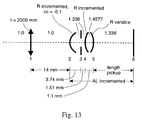
- FIG. 14 In addition to the exact ray trace performed by Oslo, a spreadsheet is shown in FIG. 14 that performs a paraxial raytrace of the system. A paraxial raytrace is mathematically simpler to perform than a real raytrace, and yields very similar results for the optical system of the eye. Both the schematic system of FIG. 13 and the mathematics used in the ray trace spreadsheet of FIG. 14 are described in detail below.
- the layout of the spreadsheet is the same as the system shown in FIG. 13 , in which light propagates from a distant object, through the spectacles at the leftmost part of the optical system, from left-to-right, until it is collected at the retina at the rightmost part of the optical system.
- the spectacles are optional in this example.
- Each surface in the optical system is explicitly treated in the spreadsheet.
- Input values in the spreadsheet are entered in the thick-boxed cells. All other cells are calculated.
- the optical system is entered as a series of surfaces.
- Each surface has an incident and an exiting refractive index, n and n', respectively, so that the power ⁇ of each surface is numerically equal to (n'-n)/R.
- the power and curvature both equal zero, and the radius is infinite.
- an equation or calculation step that yields an infinite value for a radius of a surface implies that the surface is flat, and that the surface may have additional optional aspheric terms even though its radius is infinite.
- Each surface is separated by a thickness, t.
- Two rays are traced through the system, each with its own height y at each surface, and propagation angle u between surfaces.
- the specific rays in FIG. 13 are in accordance with standard geometrical optical conventions, and are designated as a marginal ray and a chief ray.
- the refractive indices are dimensionless, the ray angles are in radians, the ray heights are in mm [or, alternately, m], and the surface powers are in mm -1 [or, alternately, diopters].
- a ray is given a set of initial conditions at a surface, and is then propagated throughout the optical system.
- a marginal ray originates from the base of the object and passes through the edge of the entrance pupil. Because the object is infinitely far away, the marginal ray enters the optical system with a ray angle of 0, and a height of 3 mm, equal to the half the entrance pupil diameter. Any suitable entrance pupil diameter may be used.
- a chief ray passes through the center of the aperture stop, with an angle at the stop chosen so that the chief ray angle in object space equals the field of view in object space.
- the true chief ray angle in object space is the tangent of the ray angle, ubar. Note that the chief ray is set at the aperture stop, then propagated in both directions away from the aperture stop. The paraxial refraction and transfer equations above are easily inverted to trace rays backwards through the system.
- a quantity, "A”, is defined as ni, the product of the refractive index n before a surface, and the incident angle i of the marginal ray at the surface.
- A is dimensionless. Note that A may also be calculated using the numerical values of n and u after the surface, rather than before; both ways produce numerically equal results.
- a quantity "B” is defined as nibar, the product of the refractive index n before a surface, and the incident angle ibar of the chief ray at the surface.
- B is also dimensionless, and may also be calculated using the numerical values of n and ubar after the surface, rather than before.
- W 131 contribution ⁇ 1 ⁇ 2 A B u ⁇ / n ⁇ ⁇ u / n / ⁇ , where y is the marginal ray height at the surface, A and B are defined above for the surface, u is the marginal ray angle before the surface, u' is the marginal ray angle after the surface, n is the refractive index before the surface, n' is the refractive index after the surface, and ⁇ is the wavelength.
- a wavelength is chosen of 555 nm, which is the peak of spectral luminous efficacy for photopic vision. Optionally, other wavelengths may be used.
- the total amount of W 131 is then the sum of these individual surface contributions. These W 131 contributions are comparable to those produced by Oslo's "Seidel Wavefront Aberration Coefficients", which are accessible through the "seiwvf' command.
- the incident medium is air, with a refractive index n air chosen to be 1.
- n air chosen to be 1.
- An object is infinitely far away, so that the marginal ray enters the spectacle with a ray angle of 0 and a height of 3 mm, equal to half the entrance pupil diameter.
- the spectacle may be left out of the calculation and the eye assumed to be emmetropic or targeted at emmetropia.
- the spectacle, surface 1 is modeled as an aberration-free thin lens with a power of -0.5 diopters. In Oslo, a "perfect" lens is used. In the spreadsheet, a single surface is used, with a power chosen to be -0.5 diopters.
- the cornea, surface 2 is modeled as a single, curved surface.
- the radius is used as an input in the spreadsheet, and typical values between 7 mm and 9 mm adequately cover the range of real cornea radii.
- the refractive index after the cornea surface in this raytracing model is the refractive index of the eye, n eye , chosen to be 1.336.
- the refractive after the cornea may be given a value different from n eye , such as 1.3375, although this change would produce only slight changes in the design presented below.
- the conic constant of the cornea varies significantly.
- a conic constant between -0.2 and 0.0 is used. This conic constant is used as an input in Oslo in addition to the radius, but the spreadsheet cannot accommodate the conic constant.
- a non-zero conic constant merely increases the absolute value of the third-order coma produced by the cornea.
- the intraocular lens cannot generate enough coma to completely offset that of the cornea, so that the optimal shape of the intraocular lens is the shape at which the third-order coma is brought closest to zero.
- the optimal lens shape is independent of the conic constant value, since the coma produced by the cornea is independent of the lens shape. This is discussed in more detail below; for now, it is sufficient to note that the paraxial spreadsheet and the real raytrace in Oslo give excellent agreement for preferred lens shape.
- the beam propagates from the cornea to the iris, denoted optically as the aperture stop, surface 3.
- the distance between them is often referred to as the anterior chamber depth, and is chosen to be 3.74 mm.
- the refractive index between the cornea and the aperture stop is n eye , which is chosen to be 1.336.
- Other refractive indices and anterior chamber depths may be used here if found to be more suitable. For example, if a two-surface corneal model were used, a refractive index value of 1.3375 would be appropriate.
- the aperture stop itself has no optical power, and the refractive index after the stop is the same as before the stop, n eye .
- the user explicitly sets surface 3 to be the aperture stop, with a diameter that floats to accommodate the incident beam size.
- the aperture stop explicitly starts the raytrace of the chief ray.
- the chief ray angle through the aperture stop is chosen so that the chief ray angle in object space equals the field of view, or 5 degrees.
- the field of view may be any other suitable value, such as 10 or 15 degrees.
- the beam propagates from the aperture stop, surface 3, to the anterior surface of the intraocular lens, surface 4.
- the propagation distance is numerically equal to the effective lens position, chosen to be 5.25 mm, minus the anterior chamber depth, chosen to be 3.74 mm, or 1.51 mm. In Oslo, this value is denoted as a "pickup".
- the refractive index between surface 3 and surface 4 is also n eye . Note that the distances and refractive indices chosen are all merely exemplary, and are not restrictive in any way.
- the anterior surface of the intraocular lens is spherical, for the purposes of this raytracing model.
- either or both of the lens surfaces may have one or more aspheric components and/or a conic constant.
- the aspherics and conics are omitted.
- the numerical value of the radius that is used in the exemplary spreadsheet of FIG. 14 is about 110 mm, which is a relatively large, positive radius. This gives a very shallow, convex curvature to the anterior surface.
- the value of curvature may be varied by the spreadsheet solver to change the value of a particular cell in the spreadsheet.
- the distance between the anterior and posterior surfaces of the lens is equal to the lens thickness, nominally about 1.1 mm, for example. This value may vary according to manufacturing techniques and preferences, and is varied manually in several of the plots that follow over the range of 1.0 mm to 1.2 mm. For comparison with the analytical formula presented in the previous section, the thickness may be set to 0.
- the refractive index of the intraocular lens is chosen to be 1.4577.
- the posterior surface of the lens, surface 5 is also spherical in this model. Like the anterior surface, it may have optional aspheric and/or conic components in the final design. In Oslo, the radius is chosen to be a variable, so that during optimization, it is varied to minimize the merit function. In the spreadsheet, the power of the surface is chosen to be a "solve" so that its value automatically sets the marginal ray height to zero at the retina.
- the anterior surface could be varied, or both the anterior and posterior surfaces could both vary.
- the distance between the anterior surface of the lens and the retina is calculated so that the axial length (i.e., the distance between the cornea and the retina) is a chosen value.
- the range of 21 mm to 26 mm for the axial length accommodates most patients, although values outside of this range may be used in this model.
- the value of thickness in the cell is easily calculated. In Oslo, this length is most easily specified as a "length pickup".
- the refractive index between the lens and the retina is n eye .
- the retina is the retina.
- the specific properties of the retina are relatively unimportant for this particular model.
- the important quantity at the retina is its incident refractive index (1.336). It is important to note on the spreadsheet that the marginal ray height at the retina is zero, thereby ensuring that an infinitely distant object forms an image at the retina itself, rather than before or after the retina surface.
- the Lagrange invariant may be calculated before or after any surface in the system. All of these quantities are also evaluated in Oslo, with minor differences arising from the fact that Oslo uses a real raytrace while the spreadsheet uses a paraxial raytrace.
- a conjugate factor Y may be calculated.
- This value is calculated and displayed numerically in the spreadsheet.
- the values of IOL power and conjugate factor are also calculated using the real value of the lens thickness (usually in the range of 1.0 mm to 1.2 mm).
- the conjugate factor is given by its defining equation above.
- the model described in this section is then used to calculate the third-order coma of the combination of the cornea and the intraocular lens, and show its behavior as a function of lens shape, X. It is shown below that for each value of lens power, there is a range of preferred shape factor, X, that reduces the absolute value of the total third-order coma in the eye system.
- the actual measured radius of curvature of a patient's cornea is highly likely to fall between 7 mm and 9 mm, so the range subtended by these three curves adequately covers a full range of patients.
- the embodiments and examples cover a broader range as well.
- the conic constant of the cornea is -0.1
- the thickness of the lens is 1.1 mm, as an example.
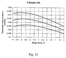
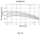
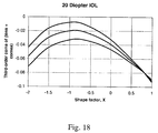
- the curves plot the reported value of third-order coma of the whole optical system of the eye versus the shape factor of the intraocular lens.
- the coma of the cornea is substantial, and it is highly desirable to use the cornea of the intraocular lens itself to offset the coma of the cornea, so that the resulting cascaded optical system has reduced coma.
- the values along the y-axis are not the values of W 131 , but are the equivalent Seidel third-order aberration coefficients as reported by Oslo (using an entrance beam radius of 4 mm and a field angle of 15 degrees).
- the values themselves are less important than the shape factor at which these curves approach a minimum absolute value of coma.
- This preferred shape factor may be read from the graphs themselves, by selecting an X value that brings the third-order coma closest to zero.
- D X should be between -3 and -2.2
- 10 D X should be between -1.9 and -1.5
- 15 D X should be between -1.3 and -1.1
- 20 D X should be between -1.0 and -0.8
- 25 D X should be between -0.8 and -0.7
- 30 D X should be between - 0.6 and -0.5.
- These preferred shape factors describe the base radii of curvature of the intraocular lens that best offsets the coma of the cornea.
- the intraocular lens with the preferred shape factor X optimally reduces the total amount of coma of the image at the retina.
- the preferred shape factor only describes the base radii of curvature; the actual surfaces in the intraocular lens may also have additional aspheric or conic terms, in addition to its base radii.
- the preferred X ranges above depend somewhat on the lens thickness, and can be recalculated for any particular thickness.
- the optimal shape of the lens is meniscus, with the concave surfaces facing away from the retina (i.e., for both lens surfaces, the center is closer to the retina than the edge is.)
- the optimal shape is bi-convex, with the more steeply curved surface facing the retina.
- the thickness of the intraocular lens is set at 1.1 mm, and the conic constant of the cornea is set at -0.1. In real lenses and real patients, these values may vary, and it is instructive to show the effects of these variations on the preferred shape factor, X.
- FIG. 21 shows that they may vary over a reasonable range without substantially affecting the values of third-order coma, or without substantially changing the conclusions of FIGs. 15-20 .
- a set of nominal conditions is chosen, with a cornea radius of 7.704 mm and an axial length of 23.45, and a 21.5 D lens that is varied over shape factor X from about -1.5 to about 1.5.
- the analysis is repeated for a lens thickness of 1.0 mm, 1.1 mm and 1.2 mm, and for a conic constant of 0, -0.1 and -0.2, yielding the nine curves shown in FIG. 21 .
- a bundling of the curves is seen at the rightmost edge of the plot, where the top bundle of curves has a conic constant of zero, the middle bundle has a conic constant of -0.1, and the bottom bundle has a conic constant of -0.2.
- each of the bundles at the rightmost edge of the plot in FIG. 21 is a plot for each of the lens thicknesses; these are indistinguishable for positive values of X, and separate slightly for negative values of X. This shows that altering the lens thickness has no significant effect on the preferred shape factor for this particular power.
- the actual thickness of the lens may be tailored to suit optical or non-optical needs.
- the lens may have a minimum thickness at its edge imposed by a particular grinding, polishing, or molding step in the manufacturing process.
- the lens may have particular rigidity requirements.
- FIG. 22 shows the preferred shape factor X as a function of intraocular lens power.
- the values of X may be obtained in Oslo from the radii of the lens after optimization, where now both radii are set as variables, and an additional operand of "CMA3" is used, in addition to "PY".
- the X values may be obtained directly from the paraxial spreadsheet, when the anterior radius is varied to set the total third-order coma as close to zero as possible.
- the only significant difference between the two calculation methods is that Oslo can use non-zero conic constants for its cornea, whereas the paraxial spreadsheet only works for purely spherical corneas.
- the curves are obtained for two discrete values of cornea radius: 7 mm and 9 mm.
- the curves for 7 mm and 9 mm typically represent the extreme values for shape factor X.
- the three curves extending to the lower left corner of the graph are for a radius of 7 mm; the three just beneath them, beginning at roughly 12 D, are for 9 mm.
- the top is for a lens thickness of 1.2 mm
- the middle is for a lens thickness of 1.1 mm
- the bottom is for a lens thickness of 1.0 mm.
- the axial length is incremented, the radii are optimized to minimize coma, then the optimized radii values are used to calculate the shape factor X.
- the preferred shape factor is less than 1, resulting in a meniscus lens with the convex surface facing the retina and the concave surface facing away from the retina.
- the preferred shape is plano-convex, with the convex side facing the retina.
- the preferred shape is bi-convex, with the most steeply curved side facing the retina.
- the values of preferred shape factor X are plotted for conic constants of 0 and -0.2, and the resulting curves lie entirely on top of one another.
- This conic independence is easily explained: the coma generated by the cornea is larger than any value of coma that the lens can generate. Therefore, the best that the lens can do is generate its maximum value of coma (of the opposite sign as the cornea's coma), to try and push the total value of coma back towards zero. This maximum value of lens coma occurs at a particular X value, which is the value reported on the graph.
- the optimal X value remains unchanged, because the optimal X still generates the maximum lens coma (of the opposite sign as the cornea) to move the total system coma back toward zero.
- the lens can generate a sufficient amount of third-order coma to completely offset that of the cornea.
- the coma of the cornea is too large to be completely cancelled by the lens.
- the cornea In practice, for a typical set of cornea conditions, such as those in FIG. 21 , the cornea generally has more third-order coma than the lens, regardless of choice of shape factor X. When this occurs, the best one can do is choose a shape factor X so that the lens generates the most amount of coma of an opposite sign of that of the cornea, to best offset the third-order coma of the cornea and reduce the total amount of coma in the eye system.
- the preferred shape factor is between -3 and - 1.6.
- the preferred shape factor is between -3 and -1.2.
- the preferred shape factor is between -1.9 and -0.8.
- the preferred shape factor is between 15 diopters and 25 diopters.
- the preferred shape factor is between -1.2 and -0.2.
- the preferred shape factor is between -0.7 and 0.
- the above optimization step does not produce a completed lens. Instead, the optimization adjusts only the base radius of curvature of the posterior lens so that the paraxial focus falls on the retina.
- one or more aspheric terms should be added to one or both of the lens surfaces.
- a conic constant may also be added to one or both of the lens surfaces.
- the paraxial raytracing spreadsheet of FIG. 14 is used to calculate the optimal shape factor X, the resulting value of X is independent of both the entrance pupil diameter (or, equivalently, the incident marginal ray height) and the field of view (or, equivalently, the incident chief ray angle). This arises from the scalability of a paraxial raytrace, and is a particularly pleasing aspect of the paraxial spreadsheet.
- the preferred shape factor adjusts the third-order coma of the lens to largely offset the coma of the cornea, so that the image at the retina has a reduced amount of third-order coma.
- This reduced-coma condition provides more relaxed manufacturing and alignment tolerances for the lens, and improved off-axis image quality.
- the preferred shape factor is largely independent of both lens thickness and the conic constant of the cornea.
- the refractive index on one side of the lens may differ from the refractive index on the opposite side of the lens.
- the numerical values of n eye in the two above equations may be replaced by the incident refractive index in the anterior equation, and the exiting refractive index in the posterior equation.
- these methods may be applied to a condition associated with an individual patient, an average patient, or a special group of patients.
- One such group could be a group of patients having undergone refractive surgery, such as PRK, LASEK, LASIK or RK.
- Another group could be a group of patients having undergone corneal surgery, such as those suffering from special ocular conditions such as kerataconous or corneal disease.
- the intraocular lens could be monofocal, bifocal, multifocal, or a phakic lens. If the IOL is a phakic lens, then the natural lens of the eye should be included in the calculations outlined here.
- the methods described herein may also be applied to individual cornea data taken from corneal topography, i.e., corneas where the individual amount of corneal spherical aberration is known.
- the methods may be applied to a model cornea that reflects average measurements for a "normal” or "special” group of patients.
- the next step in the design is the addition of aspheric terms or a conic constant to one or both of the surfaces in the lens, so that on-axis aberrations are reduced. This process is detailed in the next section.
- the lens should also have reduced spherical aberration, which improves both on-axis and off-axis performance.
- a preferred way of reducing spherical aberration is to introduce a conic constant and/or one or more aspheric terms to one or more of the surfaces on the intraocular lens. Note that adjusting the base radii of curvature affects the spherical aberration, but also affects the coma at the same time. It is preferred to first fix the coma by selecting the base radii according to the above steps, then afterwards correct the remaining spherical aberration by adding a conic constant and/or aspheric terms on one or both of the intraocular lens surfaces.
- any of the parameters of the intraocular lens may be optimized and/or toleranced. These optimizations may preferably use the base radii obtained from the preferred shape factor as a starting point, but may depart somewhat from it during the optimization process.
- FIG. 12 shows the relationship between cornea radius, axial length, and the required power of the IOL.
- a patient with an axial length of 24 mm and a cornea radius of 7.8 mm, and a patient with an axial length of 25 mm and a cornea radius of 8.3 mm both require an IOL power 20 diopters. Given this multiplicity, which set of conditions does one use when designing the lens itself?
- a reasonable assumption is that one should use an "average" radius and conic constant for the cornea, and vary the axial length to achieve the particular desired power.
- the "average" cornea values of radius and conic constant are chosen to be 7.5 mm and -0.1, respectively.
- the values of axial length are then determined from FIG. 12 to yield the appropriate value of IOL power.
- a lens designed in this manner generally performs well when used with other radius/axial length combinations that also require the same IOL power.
- the IOL is designed for a statistically "average" cornea.
- averaging schemes that may be used for measurements taken on a particular population. For instance, if the radius and conic constant are measured for a group of patients, then two exemplary ways to determine the average coma are detailed below. In one scheme, the radius measurements are averaged to form an average radius, and the conic constant measurements are averaged to form an average conic constant. Then, the average radius and average conic constant are plugged into a model of the eye to determine an average coma. In the second scheme, a value of coma is first determined for each patient in the population, then the coma values themselves are averaged to form an average coma. These two schemes are merely exemplary, and other appropriate averaging schemes may also be used.
- each shoe width where each shoe is available in a particular size, but may be specified in terms of "wide” or "narrow”.
- each lens may be made available in not just a power, but in a "high coma” or "low coma” condition.
- the various parameters of the intraocular lens are fleshed out.
- the following steps are exemplary, and show how a lens may be designed for a particular power. It will be appreciated that other design steps may be used, in addition to or in place of the following steps.
- the lens is designed for a particular power, so optical power is the primary input constraint.
- optical power is the primary input constraint.
- two quantities are measured for each patient: axial length, and radius of the cornea. From these two quantities, a formula based on thin-lens calculations determines a required optical power for the intraocular lens.
- axial length and corneal radius There are many combinations of axial length and corneal radius that produce the same required optical power, so we arbitrarily choose an average cornea radius and conic constant, and design for this particular average cornea, but with varying axial lengths to account for the range of required powers.
- a manufacturer of intraocular lenses provides off-the-shelf lenses in power increments of 0.5 D, usually in the range of 5 D to 30 D. Naturally, the power range or increments can vary from these values.
- the power determination may be based on measurements from a number of eyes or their models, using an average cornea and an average axial length.
- a lens thickness fairly early in the design stage, although the thickness may be varied at any step in the design process. Common thicknesses are in the range of 1.0 mm to 1.2 mm, although they may also vary outside this range. The thickness is commonly chosen for non-optical reasons, such as for lens rigidity, or a particular edge thickness constraint, or a particular mechanical constraint that arises from a manufacturing process. For the exemplary design detailed below, a thickness of 1.1 mm is chosen.
- the next two quantities to be determined are the radii of curvature of the anterior and posterior lens surfaces. As discussed in previous sections, these two curvatures are chosen to (1) determine the power of the lens, and (2) minimize the third-order coma in the full optical system. Spherical aberration is addressed in a later design step, but not at this point.
- the two radii of curvature may be equivalently expressed as values of lens power ⁇ and lens shape factor X.
- there is a preferred shape factor that minimizes the third-order coma in the system as shown graphically in FIG. 22 .
- One may read the values off the graph in FIG. 22 , then convert ⁇ and X back to radii for the front and rear surfaces via formulas provided above.
- the spreadsheet of FIG. 14 may directly generate the values of the radii.
- the user may define a cell as a "merit function" to be minimized.
- the value of the merit function cell is defined by the user, and may, for example, equal ((Actual power - Desired power) 2 + (Total W131) 2 ), or any other appropriate value.
- the spreadsheet can then use a solver to minimize the merit function cell, or set it as close as possible to zero, by changing the values of the "axial length" and "anterior lens curvature” cells.
- the power term in the merit function may optionally be weighted, such as by a factor of 10000 or some other appropriate weighting term.
- the solver converges, the values of the anterior and posterior radii may be read directly from the spreadsheet, along with the shape factor X and axial length, if desired. Note that the spreadsheet of FIG. 14 does not accommodate a non-zero conic constant.
- a raytracing program may be used to generate the two radii directly.
- the two radii of the lens may be set as variables, and two aberration operands may be set: PY, which sets the axial ray height at the retina as close to zero as possible, and CMA3, which ensures that the third-order coma of the whole system is brought as close as possible to zero.
- this step it is preferable to stop down the lens to a smaller entrance beam radius (say, 1 mm), and a reduced field angle (say, 1 degree), so that the lens performance is dominated by third-order spherical aberration on- and off-axis, and third-order coma off-axis, without the complications of other aberrations in the system.
- the radii produced by this step do not directly depend on the choice of entrance beam radius or field angle.
- the lens radius values produced by either the spreadsheet or the raytracing program are essentially independent of conic constant value, for values in the range of -0.2 to 0.
- the optimal shape factor X for the lens helps offset the coma of the cornea, but generally does not completely cancel it.
- the base radii of curvature of the front and back surfaces of the lens are preferably chosen to minimize the third-order coma of the whole system.
- the shape factor X is generally the only quantity that substantially affects the off-axis performance of the lens.
- aspheric and/or conic terms may be added to one or both of the lens surfaces, these primarily improve lens performance on-axis by reducing spherical aberration.
- Off-axis performance is dominated by third-order coma, and third-order coma is best reduced by adjusting the shape factor X of the lens.
- the on-axis performance may be improved by adding a conic and/or aspheric terms to one or both lens surfaces. These terms reduce spherical aberration, which affects both on-axis and off-axis performance of the lens.
- conic and/or aspheric terms may be added to both lens surfaces, it is found that having them on only one of the surfaces works adequately.
- these conic and/or aspheres are present on the surface facing the retina, which for these designs typically is more steeply curved and contains the majority of the optical power of the lens.
- the surface facing away from the retina may be left purely spherical, i.e., devoid of conic and/or aspheric terms or components.
- the aspheric terms can be placed on either or both of the anterior and posterior surfaces.
- CC conic constant
- AD fourth-order aspheric term
- AE sixth-order aspheric term
- AF eighth-order aspheric term
- Adding the aspheric terms to the second (i.e., posterior) lens surface is preferably done using a commercially-available lens design or raytracing program, such as Oslo, ZEMAX, Code V, and others.
- One approach is to set the field of view to zero (because we wish to optimize on-axis performance in this step), set the aspheric terms AD, AE and AF as variables, and optimize using on-axis spot size or on-axis wavefront error in the merit function.
- This approach works adequately, and produces functional values for AD, AE and AF.
- This approach is also fast, providing values in essentially one optimization step.
- the base radii are not set as variables, the thickness between the lens and the retina may also be set as a variable and optimized along with the other terms during this step.
- the specific values of 3 rd order, 5 th order, and 7 th order spherical aberration may all be set to zero, but this may leave some residual 9 th order spherical aberration in addition
- the lens is entered into the raytracing program of choice, that the front and rear radii of the lens are determined (from a pervious step), and that the lens is stopped down beyond its design criteria. For instance, the entrance beam radius is stopped down to 1 mm, and the field of view is stopped down to 1 degree.
- the dominant wavefront aberration should be third-order spherical aberration, or W 040 .
- W 040 third-order spherical aberration
- AD fourth-order aspheric term
- SA3 aberration operand
- the value of AD should now be set to a particular non-zero value.
- the on-axis performance of the lens should be superb, with a Strehl Ratio close to one, such as 0.999.
- the lens should show an insignificant amount of coma, such as roughly 0.02 waves or less.
- values of AD, AE and AF are obtained. These values may be fine-tuned by changing the merit function from one that minimizes individual aberrations to one that minimizes spot size or wavefront aberration.
- AD, AE and AF as variables, set the field angle to essentially zero, then optimize.
- the value of AD remained largely unchanged, the value of AE may have changed by a small amount, say 10%, and AF may have changed by a substantial amount, such as a factor of three or more.
- the resulting performance of the lens on-axis should again be superb, with a Strehl Ratio of essentially 1.0.
- Analysis of the wavefront error after this spot size optimization shows an extremely small amount of some high-order spherical aberration, with magnitudes of about 0.002 waves or less.
- both radii should not be further optimized in tandem. For instance, both radii should not be set as variables during any of the subsequent optimization steps, such as the elimination of third-order spherical aberration.
- the shape factor X also influences the amount of spherical aberration in the lens, but because spherical aberration can be corrected by the addition of aspheric terms, we use X to instead correct for coma, which is not easily influenced by aspheric coefficients.
- the step-by-step optimization process is informative for the designer, it may be skipped altogether by setting AD, AE and AF of the back lens surface as variables, setting the field angle to essentially zero, opening the entrance pupil radius to 3 mm or 4 mm (or any other suitable value), and optimizing for minimum spot size or minimum wavefront error.
- the aspheric terms AD, AE and AF of one of the lens surfaces thus complete the lens design.
- the aspheric terms are applied to the back surface of the lens, they may just as easily be applied to the front surface, applied to both, or divided between the two. Switching the aspheric terms from one surface to the other has little effect on the overall lens performance. There may be some advantage to making one particular side of the lens aspheric, such as commonality of a surface profile among various designs, say if a particular mold is to be shared among the designs.
- This design process may be repeated as often as required for different powers, so that a complete line of off-the-shelf lenses may accommodate the full range of patients.
- a typical range of required powers is 5 D to 30 D.
- a typical power increment between available lenses may be 0.5 D, although 0.25 D or another suitable increment may be used.
- each of the designs shown in this section is designed in the same manner, as follows.
- the spreadsheet of FIG. 14 is used to find the "optimal" or "preferred" starting point, with an X value that minimizes the third-order coma of the full optical system.
- the spreadsheet provides, equivalently, the radii of the front and rear surfaces of the lens, as well as the appropriate surface-to-surface spacings. All of these starting points are then optimized in Oslo.
- the aspheric terms AD, AE and AF are added to the second surface of the lens using a merit function that minimizes the RMS spot size, and performing the optimization at an entrance pupil radius of 3 mm and zero field angle.
- All the lenses are 1.1 mm thick, with a refractive index of 1.4577, and are designed for a cornea with a radius of 7.5 mm and a conic constant of -0.15. This cornea is intended to represent an "average" cornea.
- FIGs. 23 and 24 Six sample designs are carried to completion, and are shown in FIGs. 23 and 24 .
- the designs of FIG. 23 which are for powers of 5, 10 and 15 diopters, are drawn with a part diameter of 8 mm.
- the designs of FIG. 24 which are for powers of 20, 25 and 30 mm, are drawn with a part diameter of 6 mm.
- the actual thickness of the part may be altered to accommodate any non-optical concerns, like a minimum edge thickness, for example.
- each of these designs uses a center thickness of 1.1 mm, although any suitable thickness may be used.
- the 5 D lens has a shape factor X of -2.23, an anterior radius of -39.74 mm, and a posterior radius of -15.13 mm.
- the distance between the lens and the retina is 22.03 mm.
- the 10 D lens has a shape factor X of -1.58, an anterior radius of -41.85 mm, and a posterior radius of -9.449 mm.
- the distance between the lens and the retina is 20.36 mm.
- the 15 D lens has a shape factor X of -1.19, an anterior radius of -86.72 mm, and a posterior radius of -7.427 mm.
- the distance between the lens and the retina is 18.88 mm.
- the 20 D lens has a shape factor X of -0.93, an anterior radius of 170.5 mm, and a posterior radius of -6.307 mm.
- the distance between the lens and the retina is 17.58 mm.
- the 25 D lens has a shape factor X of -0.75, an anterior radius of 39.01 mm, and a posterior radius of -5.549 mm.
- the distance between the lens and the retina is 16.45 mm.
- the 30 D lens has a shape factor X of -0.62, an anterior radius of 21.47mm, and a posterior radius of -4.980 mm.
- the distance between the lens and the retina is 15.44 mm.
Landscapes
- Health & Medical Sciences (AREA)
- Life Sciences & Earth Sciences (AREA)
- Engineering & Computer Science (AREA)
- Ophthalmology & Optometry (AREA)
- Animal Behavior & Ethology (AREA)
- Veterinary Medicine (AREA)
- Public Health (AREA)
- Biomedical Technology (AREA)
- Heart & Thoracic Surgery (AREA)
- General Health & Medical Sciences (AREA)
- Biophysics (AREA)
- Surgery (AREA)
- Molecular Biology (AREA)
- Medical Informatics (AREA)
- Physics & Mathematics (AREA)
- Signal Processing (AREA)
- Cardiology (AREA)
- Oral & Maxillofacial Surgery (AREA)
- Transplantation (AREA)
- Vascular Medicine (AREA)
- Prostheses (AREA)
Claims (5)
- Cristallin artificiel (113) ayant une puissance optique P et un facteur de forme X, destiné à être implanté dans un oeil ayant une cornée, comprenant :une surface antérieure (4) ayant un rayon antérieur Ra ;une surface postérieure (5) ayant un rayon postérieur Rp ; etdans lequel le rayon antérieur Ra et le rayon postérieur Rp déterminent la puissance optique et le facteur de forme ;lequel cristallin a un indice de réfraction n ;lequel cristallin a un indice de réfraction incident ni ;lequel cristallin a un indice de réfraction sortant ne ;lequel cristallin a une épaisseur T ; etdans lequel la puissance optique P est déterminée par

 dans lequel, si la puissance optique P est comprise entre 0 dioptrie et 10 dioptries, il a un facteur de forme X compris entre -3 et -1,6, oudans lequel, si la puissance optique P est comprise entre 5 dioptries et 15 dioptries, il a un facteur de forme X compris entre -3 et 1,2, oudans lequel, si la puissance optique P est comprise entre 10 dioptries et 20 dioptries, il a un facteur de forme X compris entre -1,9 et -0,8, oudans lequel, si la puissance optique P est comprise entre 15 dioptries et 25 dioptries, il a un facteur de forme X compris entre -1,5 et -0,5, oudans lequel, si la puissance optique P est comprise entre 20 dioptries et 30 dioptries, il a un facteur de forme X compris entre -1,2 et -0,2, oudans lequel, si la puissance optique P est supérieure à 30 dioptries, il a un facteur de forme X compris entre -0,7 et 0.
 - Cristallin artificiel selon la revendication 1, dans lequel, si le cristallin artificiel a une puissance optique P de 5 dioptries, il a un facteur de forme X compris entre -3 et -2,2 ; ou
dans lequel, si le cristallin artificiel a une puissance optique P de 10 dioptries, il a un facteur de forme X compris entre -1,9 et -1,5 ; ou
dans lequel, si le cristallin artificiel a une puissance optique P de 15 dioptries, il a un facteur de forme X compris entre -1,3 et -1,1 ; ou
dans lequel, si le cristallin artificiel a une puissance optique P de 20 dioptries, il a un facteur de forme X compris entre -1,0 et -0,8 ; ou
dans lequel, si le cristallin artificiel a une puissance optique P de 25 dioptries, il a un facteur de forme X compris entre -0,8 et -0,7 ; ou
dans lequel, si le cristallin artificiel a une puissance optique P de 30 dioptries, il a un facteur de forme X compris entre -0,6 et -0,5. - Cristallin artificiel selon la revendication 1 ou 2, dans lequel la puissance optique est inférieure à 20 dioptries.
- Cristallin artificiel selon la revendication 3, dans lequel la puissance optique est inférieure à 15 dioptries.
- Cristallin selon l'une quelconque des revendications précédentes, dans lequel le facteur de forme minimise le coma de l'oeil pour la valeur de puissance optique ; en conséquence de quoi le coma du cristallin compense le coma de la cornée.
Applications Claiming Priority (2)
| Application Number | Priority Date | Filing Date | Title |
|---|---|---|---|
| US11/260,013 US8801781B2 (en) | 2005-10-26 | 2005-10-26 | Intraocular lens for correcting corneal coma |
| PCT/EP2006/010346 WO2007048615A1 (fr) | 2005-10-26 | 2006-10-26 | Cristallin intraoculaire servant a corriger une coma corneenne |
Publications (2)
| Publication Number | Publication Date |
|---|---|
| EP1940318A1 EP1940318A1 (fr) | 2008-07-09 |
| EP1940318B1 true EP1940318B1 (fr) | 2016-11-23 |
Family
ID=37564070
Family Applications (1)
| Application Number | Title | Priority Date | Filing Date |
|---|---|---|---|
| EP06806569.7A Active EP1940318B1 (fr) | 2005-10-26 | 2006-10-26 | Cristallin intraoculaire servant a corriger une coma corneenne |
Country Status (5)
| Country | Link |
|---|---|
| US (1) | US8801781B2 (fr) |
| EP (1) | EP1940318B1 (fr) |
| AU (1) | AU2006308099B2 (fr) |
| CA (1) | CA2627666C (fr) |
| WO (1) | WO2007048615A1 (fr) |
Families Citing this family (31)
| Publication number | Priority date | Publication date | Assignee | Title |
|---|---|---|---|---|
| IL145015A0 (en) | 2001-08-21 | 2002-06-30 | Nun Yehoshua Ben | Accommodating lens |
| IL161706A0 (en) * | 2004-04-29 | 2004-09-27 | Nulens Ltd | Intraocular lens fixation device |
| EP1890650A2 (fr) | 2005-03-30 | 2008-02-27 | Nulens Ltd | Ensembles lentille intraoculaire accommodative (aiol) et composants separes pour lesdits ensembles |
| USD702346S1 (en) | 2007-03-05 | 2014-04-08 | Nulens Ltd. | Haptic end plate for use in an intraocular assembly |
| WO2008107882A2 (fr) * | 2007-03-05 | 2008-09-12 | Nulens Ltd | Lentilles intraoculaires à accommodation unitaires (aiol) et éléments de base discrets destinés à une utilisation avec ces lentilles |
| ES2313837B1 (es) * | 2007-05-07 | 2009-12-17 | Consejo Superior De Investigaciones Cientificas | Diseño analitico de lentes intraoculares. |
| EP2315559B1 (fr) * | 2008-07-24 | 2012-01-25 | Nulens Ltd | Capsules de lentilles intraoculaires d'accommodation (aiol) |
| US20100125331A1 (en) * | 2008-11-19 | 2010-05-20 | Simpson Michael J | Aspheric intraocular lens with improved control of aberrations |
| US8210683B2 (en) * | 2009-08-27 | 2012-07-03 | Virginia Mason Medical Center | No-history method for intraocular lens power adjustment after excimer laser refractive surgery |
| US7828435B1 (en) | 2010-02-03 | 2010-11-09 | Denis Rehse | Method for designing an anterior curve of a contact lens |
| ES2374916B1 (es) | 2010-06-02 | 2013-01-30 | Consejo Superior De Investigaciones Científicas (Csic) | Procedimiento para elaborar una lente intraocular monofocal asférica isoplanática y lente obtenida empleando dicho procedimiento. |
| US9931200B2 (en) | 2010-12-17 | 2018-04-03 | Amo Groningen B.V. | Ophthalmic devices, systems, and methods for optimizing peripheral vision |
| TWI588560B (zh) | 2012-04-05 | 2017-06-21 | 布萊恩荷登視覺協會 | 用於屈光不正之鏡片、裝置、方法及系統 |
| US9201250B2 (en) | 2012-10-17 | 2015-12-01 | Brien Holden Vision Institute | Lenses, devices, methods and systems for refractive error |
| EP2908773B1 (fr) | 2012-10-17 | 2024-01-03 | Brien Holden Vision Institute | Lentilles, dispositifs, procédés et systèmes pour erreur de réfraction |
| AU2014228357B2 (en) | 2013-03-11 | 2018-08-23 | Johnson & Johnson Surgical Vision, Inc. | Intraocular lens that matches an image surface to a retinal shape, and method of designing same |
| WO2016038470A2 (fr) | 2014-03-10 | 2016-03-17 | Amo Groningen B.V. | Lentille intra-oculaire formant doublet qui améliore la vision globale en cas de perte localisée de la fonction rétinienne |
| WO2015177651A1 (fr) | 2014-04-21 | 2015-11-26 | Amo Groningen B.V. | Dispositifs ophtalmiques, système et procédés qui améliorent la vision périphérique |
| US20160038277A1 (en) * | 2014-08-11 | 2016-02-11 | Amo Development, Llc | Optical Surface Systems and Methods for Treatment of Presbyopia and Other Vision Conditions |
| EP3426191B1 (fr) | 2016-03-11 | 2024-09-11 | Amo Groningen B.V. | Lentilles intraoculaires améliorant la vision périphérique |
| US11096778B2 (en) | 2016-04-19 | 2021-08-24 | Amo Groningen B.V. | Ophthalmic devices, system and methods that improve peripheral vision |
| IL245775A0 (en) | 2016-05-22 | 2016-08-31 | Joshua Ben Nun | Hybrid accommodative intraocular lens |
| WO2018037356A1 (fr) | 2016-08-23 | 2018-03-01 | Medicem Ophthalmic (Cy) Limited | Lentilles ophtalmiques présentant des surfaces optiques asphériques et leur procédé de fabrication |
| TW201927262A (zh) * | 2017-12-20 | 2019-07-16 | 瑞士商諾華公司 | 具有前偏置光學設計之眼內透鏡 |
| GB2578639A (en) | 2018-11-02 | 2020-05-20 | Rayner Intraocular Lenses Ltd | Hybrid accommodating intraocular lens assemblages including discrete lens unit with segmented lens haptics |
| CN120053147A (zh) * | 2018-11-23 | 2025-05-30 | 锐视眼科有限公司 | 用于黄斑变性患者的扩展黄斑视觉的新式单焦点型人工晶状体 |
| CN110123488B (zh) * | 2019-05-27 | 2023-12-29 | 中国计量科学研究院 | 人工晶状体屈光度校验镜片及定值方法 |
| WO2021007377A1 (fr) * | 2019-07-09 | 2021-01-14 | Aaren Scientific Inc. | Conceptions de lentille intraoculaire pour résultat clinique optimal |
| EP4595040A1 (fr) | 2022-09-29 | 2025-08-06 | Amo Groningen B.V. | Tests de simulateur de conduite pour déterminer l'impact fonctionnel d'erreurs optiques périphériques |
| CA3268991A1 (fr) | 2022-09-29 | 2024-04-04 | Amo Groningen B.V. | Système et procédé de détermination de l'impact d'erreurs optiques périphériques sur la locomotion d'un patient |
| US20240374375A1 (en) * | 2023-03-31 | 2024-11-14 | Amo Groningen B.V. | Intraocular Lens with Power Factor and Structure for Improved Peripheral Vision |
Citations (5)
| Publication number | Priority date | Publication date | Assignee | Title |
|---|---|---|---|---|
| US5123921A (en) * | 1987-09-14 | 1992-06-23 | Nestle S.A. | Synthetic intracorneal lines and method of manufacture |
| WO1993007840A1 (fr) * | 1991-10-15 | 1993-04-29 | Advanced Corneal Systems, Inc. | Orthokeratologie enzymatique |
| US20050192667A1 (en) * | 2004-02-05 | 2005-09-01 | Schachar Elise N. | Near vision enhancing intraocular lens |
| US20050203619A1 (en) * | 2003-03-31 | 2005-09-15 | Altmann Griffith E. | Aspheric lenses and lens family |
| WO2006108004A2 (fr) * | 2005-04-05 | 2006-10-12 | Alcon, Inc. | Facteurs de forme de lio optimum pour l'oeil humain |
Family Cites Families (25)
| Publication number | Priority date | Publication date | Assignee | Title |
|---|---|---|---|---|
| US5236970A (en) * | 1987-02-05 | 1993-08-17 | Allergan, Inc. | Optically clear reinforced silicone elastomers of high optical refractive index and improved mechanical properties for use in intraocular lenses |
| US6007747A (en) * | 1987-08-24 | 1999-12-28 | Pharmacia & Upjohn Company | Method of making an aspheric soft lens |
| FR2647227B1 (fr) * | 1989-05-19 | 1991-08-23 | Essilor Int | Composant optique, tel qu'implant intra-oculaire ou lentille de contact, propre a la correction de la vision d'un individu |
| US5050981A (en) * | 1990-07-24 | 1991-09-24 | Johnson & Johnson Vision Products, Inc. | Lens design method and resulting aspheric lens |
| US5444106A (en) * | 1992-04-21 | 1995-08-22 | Kabi Pharmacia Ophthalmics, Inc. | High refractive index silicone compositions |
| US5282852A (en) * | 1992-09-02 | 1994-02-01 | Alcon Surgical, Inc. | Method of calculating the required power of an intraocular lens |
| US5760871A (en) * | 1993-01-06 | 1998-06-02 | Holo-Or Ltd. | Diffractive multi-focal lens |
| US5489302A (en) * | 1994-05-24 | 1996-02-06 | Skottun; Bernt C. | Accommodating intraocular lens |
| SE9501714D0 (sv) * | 1995-05-09 | 1995-05-09 | Pharmacia Ab | A method of selecting an intraocular lens to be implanted into an eye |
| US20040148022A1 (en) * | 1996-03-18 | 2004-07-29 | Eggleston Harry C. | Modular intraocular implant |
| US5777719A (en) * | 1996-12-23 | 1998-07-07 | University Of Rochester | Method and apparatus for improving vision and the resolution of retinal images |
| US6215096B1 (en) | 1997-01-21 | 2001-04-10 | TECHNOMED GESELLSCHAFT FüR MED. UND MED.-TECHN. SYSTEME MBH | Method for determining a required shape for at least one surface of an artificial or natural part of an eye which is intersected by a path of rays through the pupil of the eye, and device for the manufacture of an artificial lens |
| US6224211B1 (en) * | 1999-06-08 | 2001-05-01 | Medjet, Inc. | Super vision |
| US6050687A (en) * | 1999-06-11 | 2000-04-18 | 20/10 Perfect Vision Optische Geraete Gmbh | Method and apparatus for measurement of the refractive properties of the human eye |
| US6413276B1 (en) * | 2000-04-26 | 2002-07-02 | Emmetropia, Inc. | Modified intraocular lens and method of correcting optical aberrations therein |
| US6609793B2 (en) * | 2000-05-23 | 2003-08-26 | Pharmacia Groningen Bv | Methods of obtaining ophthalmic lenses providing the eye with reduced aberrations |
| US6474814B1 (en) * | 2000-09-08 | 2002-11-05 | Florida Optical Engineering, Inc | Multifocal ophthalmic lens with induced aperture |
| SE0004829D0 (sv) * | 2000-12-22 | 2000-12-22 | Pharmacia Groningen Bv | Methods of obtaining ophthalmic lenses providing the eye with reduced aberrations |
| US7111938B2 (en) | 2001-04-27 | 2006-09-26 | Novartis Ag | Automatic lens design and manufacturing system |
| IL143503A0 (en) | 2001-05-31 | 2002-04-21 | Visionix Ltd | Aberration correction spectacle lens |
| US6761454B2 (en) | 2002-02-13 | 2004-07-13 | Ophthonix, Inc. | Apparatus and method for determining objective refraction using wavefront sensing |
| US7896916B2 (en) * | 2002-11-29 | 2011-03-01 | Amo Groningen B.V. | Multifocal ophthalmic lens |
| SE0203564D0 (sv) | 2002-11-29 | 2002-11-29 | Pharmacia Groningen Bv | Multifocal opthalmic lens |
| US7036931B2 (en) * | 2003-01-29 | 2006-05-02 | Novartis Ag | Ophthalmic lenses |
| US20050043794A1 (en) * | 2003-03-31 | 2005-02-24 | Edward Geraghty | Aspheric intraocular lens |
-
2005
- 2005-10-26 US US11/260,013 patent/US8801781B2/en active Active
-
2006
- 2006-10-26 AU AU2006308099A patent/AU2006308099B2/en not_active Ceased
- 2006-10-26 WO PCT/EP2006/010346 patent/WO2007048615A1/fr not_active Ceased
- 2006-10-26 EP EP06806569.7A patent/EP1940318B1/fr active Active
- 2006-10-26 CA CA2627666A patent/CA2627666C/fr active Active
Patent Citations (5)
| Publication number | Priority date | Publication date | Assignee | Title |
|---|---|---|---|---|
| US5123921A (en) * | 1987-09-14 | 1992-06-23 | Nestle S.A. | Synthetic intracorneal lines and method of manufacture |
| WO1993007840A1 (fr) * | 1991-10-15 | 1993-04-29 | Advanced Corneal Systems, Inc. | Orthokeratologie enzymatique |
| US20050203619A1 (en) * | 2003-03-31 | 2005-09-15 | Altmann Griffith E. | Aspheric lenses and lens family |
| US20050192667A1 (en) * | 2004-02-05 | 2005-09-01 | Schachar Elise N. | Near vision enhancing intraocular lens |
| WO2006108004A2 (fr) * | 2005-04-05 | 2006-10-12 | Alcon, Inc. | Facteurs de forme de lio optimum pour l'oeil humain |
Also Published As
| Publication number | Publication date |
|---|---|
| US8801781B2 (en) | 2014-08-12 |
| US20070093891A1 (en) | 2007-04-26 |
| CA2627666C (fr) | 2015-12-15 |
| EP1940318A1 (fr) | 2008-07-09 |
| WO2007048615A1 (fr) | 2007-05-03 |
| AU2006308099B2 (en) | 2013-07-04 |
| AU2006308099A1 (en) | 2007-05-03 |
| CA2627666A1 (fr) | 2007-05-03 |
Similar Documents
| Publication | Publication Date | Title |
|---|---|---|
| AU2006308099B2 (en) | Intraocular lens for correcting corneal coma | |
| JP7048698B2 (ja) | 被写界深度延長及び遠見視力向上を伴う眼科インプラント | |
| US20240008973A1 (en) | Ophthalmic implants with extended depth of field and enhanced distance visual acuity | |
| US7381221B2 (en) | Multi-zonal monofocal intraocular lens for correcting optical aberrations | |
| AU2018226512B2 (en) | Methods of providing extended depth of field and/or enhanced distance visual acuity | |
| WO2009142961A1 (fr) | Lentille intraoculaire optimisée | |
| US20240374375A1 (en) | Intraocular Lens with Power Factor and Structure for Improved Peripheral Vision | |
| US20250073020A1 (en) | Ophthalmic lenses with first and second portions | |
| CA3016987C (fr) | Implants ophtalmiques offrant une profondeur de champ etendue et une meilleure acuite visuelle de loin | |
| HK1262100B (en) | Ophthalmic implants with extended depth of field and enhanced distance visual acuity |
Legal Events
| Date | Code | Title | Description |
|---|---|---|---|
| PUAI | Public reference made under article 153(3) epc to a published international application that has entered the european phase |
Free format text: ORIGINAL CODE: 0009012 |
|
| 17P | Request for examination filed |
Effective date: 20080318 |
|
| AK | Designated contracting states |
Kind code of ref document: A1 Designated state(s): AT BE BG CH CY CZ DE DK EE ES FI FR GB GR HU IE IS IT LI LT LU LV MC NL PL PT RO SE SI SK TR |
|
| 17Q | First examination report despatched |
Effective date: 20110512 |
|
| DAX | Request for extension of the european patent (deleted) | ||
| GRAP | Despatch of communication of intention to grant a patent |
Free format text: ORIGINAL CODE: EPIDOSNIGR1 |
|
| RIN1 | Information on inventor provided before grant (corrected) |
Inventor name: PIERS, PATRICIA Inventor name: TABERNERO, JUAN Inventor name: ARTAL, PABLO |
|
| INTG | Intention to grant announced |
Effective date: 20160610 |
|
| GRAS | Grant fee paid |
Free format text: ORIGINAL CODE: EPIDOSNIGR3 |
|
| GRAA | (expected) grant |
Free format text: ORIGINAL CODE: 0009210 |
|
| AK | Designated contracting states |
Kind code of ref document: B1 Designated state(s): AT BE BG CH CY CZ DE DK EE ES FI FR GB GR HU IE IS IT LI LT LU LV MC NL PL PT RO SE SI SK TR |
|
| REG | Reference to a national code |
Ref country code: GB Ref legal event code: FG4D |
|
| REG | Reference to a national code |
Ref country code: CH Ref legal event code: EP |
|
| REG | Reference to a national code |
Ref country code: IE Ref legal event code: FG4D |
|
| REG | Reference to a national code |
Ref country code: AT Ref legal event code: REF Ref document number: 847165 Country of ref document: AT Kind code of ref document: T Effective date: 20161215 |
|
| REG | Reference to a national code |
Ref country code: DE Ref legal event code: R096 Ref document number: 602006051032 Country of ref document: DE |
|
| REG | Reference to a national code |
Ref country code: NL Ref legal event code: FP |
|
| PG25 | Lapsed in a contracting state [announced via postgrant information from national office to epo] |
Ref country code: LV Free format text: LAPSE BECAUSE OF FAILURE TO SUBMIT A TRANSLATION OF THE DESCRIPTION OR TO PAY THE FEE WITHIN THE PRESCRIBED TIME-LIMIT Effective date: 20161123 |
|
| REG | Reference to a national code |
Ref country code: LT Ref legal event code: MG4D |
|
| REG | Reference to a national code |
Ref country code: AT Ref legal event code: MK05 Ref document number: 847165 Country of ref document: AT Kind code of ref document: T Effective date: 20161123 |
|
| PG25 | Lapsed in a contracting state [announced via postgrant information from national office to epo] |
Ref country code: SE Free format text: LAPSE BECAUSE OF FAILURE TO SUBMIT A TRANSLATION OF THE DESCRIPTION OR TO PAY THE FEE WITHIN THE PRESCRIBED TIME-LIMIT Effective date: 20161123 Ref country code: GR Free format text: LAPSE BECAUSE OF FAILURE TO SUBMIT A TRANSLATION OF THE DESCRIPTION OR TO PAY THE FEE WITHIN THE PRESCRIBED TIME-LIMIT Effective date: 20170224 Ref country code: LT Free format text: LAPSE BECAUSE OF FAILURE TO SUBMIT A TRANSLATION OF THE DESCRIPTION OR TO PAY THE FEE WITHIN THE PRESCRIBED TIME-LIMIT Effective date: 20161123 |
|
| PG25 | Lapsed in a contracting state [announced via postgrant information from national office to epo] |
Ref country code: AT Free format text: LAPSE BECAUSE OF FAILURE TO SUBMIT A TRANSLATION OF THE DESCRIPTION OR TO PAY THE FEE WITHIN THE PRESCRIBED TIME-LIMIT Effective date: 20161123 Ref country code: PT Free format text: LAPSE BECAUSE OF FAILURE TO SUBMIT A TRANSLATION OF THE DESCRIPTION OR TO PAY THE FEE WITHIN THE PRESCRIBED TIME-LIMIT Effective date: 20170323 Ref country code: FI Free format text: LAPSE BECAUSE OF FAILURE TO SUBMIT A TRANSLATION OF THE DESCRIPTION OR TO PAY THE FEE WITHIN THE PRESCRIBED TIME-LIMIT Effective date: 20161123 Ref country code: PL Free format text: LAPSE BECAUSE OF FAILURE TO SUBMIT A TRANSLATION OF THE DESCRIPTION OR TO PAY THE FEE WITHIN THE PRESCRIBED TIME-LIMIT Effective date: 20161123 Ref country code: ES Free format text: LAPSE BECAUSE OF FAILURE TO SUBMIT A TRANSLATION OF THE DESCRIPTION OR TO PAY THE FEE WITHIN THE PRESCRIBED TIME-LIMIT Effective date: 20161123 |
|
| PG25 | Lapsed in a contracting state [announced via postgrant information from national office to epo] |
Ref country code: RO Free format text: LAPSE BECAUSE OF FAILURE TO SUBMIT A TRANSLATION OF THE DESCRIPTION OR TO PAY THE FEE WITHIN THE PRESCRIBED TIME-LIMIT Effective date: 20161123 Ref country code: SK Free format text: LAPSE BECAUSE OF FAILURE TO SUBMIT A TRANSLATION OF THE DESCRIPTION OR TO PAY THE FEE WITHIN THE PRESCRIBED TIME-LIMIT Effective date: 20161123 Ref country code: EE Free format text: LAPSE BECAUSE OF FAILURE TO SUBMIT A TRANSLATION OF THE DESCRIPTION OR TO PAY THE FEE WITHIN THE PRESCRIBED TIME-LIMIT Effective date: 20161123 Ref country code: DK Free format text: LAPSE BECAUSE OF FAILURE TO SUBMIT A TRANSLATION OF THE DESCRIPTION OR TO PAY THE FEE WITHIN THE PRESCRIBED TIME-LIMIT Effective date: 20161123 Ref country code: CZ Free format text: LAPSE BECAUSE OF FAILURE TO SUBMIT A TRANSLATION OF THE DESCRIPTION OR TO PAY THE FEE WITHIN THE PRESCRIBED TIME-LIMIT Effective date: 20161123 |
|
| REG | Reference to a national code |
Ref country code: DE Ref legal event code: R097 Ref document number: 602006051032 Country of ref document: DE |
|
| PG25 | Lapsed in a contracting state [announced via postgrant information from national office to epo] |
Ref country code: IT Free format text: LAPSE BECAUSE OF FAILURE TO SUBMIT A TRANSLATION OF THE DESCRIPTION OR TO PAY THE FEE WITHIN THE PRESCRIBED TIME-LIMIT Effective date: 20161123 Ref country code: BE Free format text: LAPSE BECAUSE OF FAILURE TO SUBMIT A TRANSLATION OF THE DESCRIPTION OR TO PAY THE FEE WITHIN THE PRESCRIBED TIME-LIMIT Effective date: 20161123 Ref country code: BG Free format text: LAPSE BECAUSE OF FAILURE TO SUBMIT A TRANSLATION OF THE DESCRIPTION OR TO PAY THE FEE WITHIN THE PRESCRIBED TIME-LIMIT Effective date: 20170223 |
|
| REG | Reference to a national code |
Ref country code: FR Ref legal event code: PLFP Year of fee payment: 12 |
|
| PLBE | No opposition filed within time limit |
Free format text: ORIGINAL CODE: 0009261 |
|
| STAA | Information on the status of an ep patent application or granted ep patent |
Free format text: STATUS: NO OPPOSITION FILED WITHIN TIME LIMIT |
|
| 26N | No opposition filed |
Effective date: 20170824 |
|
| PG25 | Lapsed in a contracting state [announced via postgrant information from national office to epo] |
Ref country code: SI Free format text: LAPSE BECAUSE OF FAILURE TO SUBMIT A TRANSLATION OF THE DESCRIPTION OR TO PAY THE FEE WITHIN THE PRESCRIBED TIME-LIMIT Effective date: 20161123 |
|
| REG | Reference to a national code |
Ref country code: CH Ref legal event code: NV Representative=s name: E. BLUM AND CO. AG PATENT- UND MARKENANWAELTE , CH |
|
| PG25 | Lapsed in a contracting state [announced via postgrant information from national office to epo] |
Ref country code: MC Free format text: LAPSE BECAUSE OF FAILURE TO SUBMIT A TRANSLATION OF THE DESCRIPTION OR TO PAY THE FEE WITHIN THE PRESCRIBED TIME-LIMIT Effective date: 20161123 |
|
| REG | Reference to a national code |
Ref country code: IE Ref legal event code: MM4A |
|
| PG25 | Lapsed in a contracting state [announced via postgrant information from national office to epo] |
Ref country code: LU Free format text: LAPSE BECAUSE OF NON-PAYMENT OF DUE FEES Effective date: 20171026 |
|
| REG | Reference to a national code |
Ref country code: FR Ref legal event code: PLFP Year of fee payment: 13 |
|
| PG25 | Lapsed in a contracting state [announced via postgrant information from national office to epo] |
Ref country code: IE Free format text: LAPSE BECAUSE OF NON-PAYMENT OF DUE FEES Effective date: 20171026 |
|
| PG25 | Lapsed in a contracting state [announced via postgrant information from national office to epo] |
Ref country code: HU Free format text: LAPSE BECAUSE OF FAILURE TO SUBMIT A TRANSLATION OF THE DESCRIPTION OR TO PAY THE FEE WITHIN THE PRESCRIBED TIME-LIMIT; INVALID AB INITIO Effective date: 20061026 |
|
| PG25 | Lapsed in a contracting state [announced via postgrant information from national office to epo] |
Ref country code: CY Free format text: LAPSE BECAUSE OF NON-PAYMENT OF DUE FEES Effective date: 20161123 |
|
| PGFP | Annual fee paid to national office [announced via postgrant information from national office to epo] |
Ref country code: FR Payment date: 20190913 Year of fee payment: 14 |
|
| PG25 | Lapsed in a contracting state [announced via postgrant information from national office to epo] |
Ref country code: TR Free format text: LAPSE BECAUSE OF FAILURE TO SUBMIT A TRANSLATION OF THE DESCRIPTION OR TO PAY THE FEE WITHIN THE PRESCRIBED TIME-LIMIT Effective date: 20161123 |
|
| PG25 | Lapsed in a contracting state [announced via postgrant information from national office to epo] |
Ref country code: IS Free format text: LAPSE BECAUSE OF FAILURE TO SUBMIT A TRANSLATION OF THE DESCRIPTION OR TO PAY THE FEE WITHIN THE PRESCRIBED TIME-LIMIT Effective date: 20170323 |
|
| PG25 | Lapsed in a contracting state [announced via postgrant information from national office to epo] |
Ref country code: FR Free format text: LAPSE BECAUSE OF NON-PAYMENT OF DUE FEES Effective date: 20201031 |
|
| PGFP | Annual fee paid to national office [announced via postgrant information from national office to epo] |
Ref country code: CH Payment date: 20221010 Year of fee payment: 17 |
|
| P01 | Opt-out of the competence of the unified patent court (upc) registered |
Effective date: 20230526 |
|
| PGFP | Annual fee paid to national office [announced via postgrant information from national office to epo] |
Ref country code: GB Payment date: 20230907 Year of fee payment: 18 |
|
| REG | Reference to a national code |
Ref country code: CH Ref legal event code: PL |
|
| PG25 | Lapsed in a contracting state [announced via postgrant information from national office to epo] |
Ref country code: CH Free format text: LAPSE BECAUSE OF NON-PAYMENT OF DUE FEES Effective date: 20231031 |
|
| PG25 | Lapsed in a contracting state [announced via postgrant information from national office to epo] |
Ref country code: CH Free format text: LAPSE BECAUSE OF NON-PAYMENT OF DUE FEES Effective date: 20231031 |
|
| PGFP | Annual fee paid to national office [announced via postgrant information from national office to epo] |
Ref country code: NL Payment date: 20240917 Year of fee payment: 19 |
|
| PGFP | Annual fee paid to national office [announced via postgrant information from national office to epo] |
Ref country code: DE Payment date: 20240904 Year of fee payment: 19 |
|
| GBPC | Gb: european patent ceased through non-payment of renewal fee |
Effective date: 20241026 |
|
| PG25 | Lapsed in a contracting state [announced via postgrant information from national office to epo] |
Ref country code: GB Free format text: LAPSE BECAUSE OF NON-PAYMENT OF DUE FEES Effective date: 20241026 |