EP1940568B1 - Procede de fabrication de lames de rasoir - Google Patents
Procede de fabrication de lames de rasoir Download PDFInfo
- Publication number
- EP1940568B1 EP1940568B1 EP06809670A EP06809670A EP1940568B1 EP 1940568 B1 EP1940568 B1 EP 1940568B1 EP 06809670 A EP06809670 A EP 06809670A EP 06809670 A EP06809670 A EP 06809670A EP 1940568 B1 EP1940568 B1 EP 1940568B1
- Authority
- EP
- European Patent Office
- Prior art keywords
- strip material
- lengthwise
- edge region
- blade edge
- extending
- Prior art date
- Legal status (The legal status is an assumption and is not a legal conclusion. Google has not performed a legal analysis and makes no representation as to the accuracy of the status listed.)
- Active
Links
- 238000004519 manufacturing process Methods 0.000 title claims abstract description 7
- 238000000034 method Methods 0.000 title claims description 38
- 239000000463 material Substances 0.000 claims abstract description 98
- 238000003825 pressing Methods 0.000 claims description 9
- 229910001220 stainless steel Inorganic materials 0.000 description 10
- 239000010935 stainless steel Substances 0.000 description 10
- 239000002243 precursor Substances 0.000 description 8
- 238000005096 rolling process Methods 0.000 description 6
- 238000004804 winding Methods 0.000 description 3
- 238000005520 cutting process Methods 0.000 description 2
- -1 for example Substances 0.000 description 2
- 239000002184 metal Substances 0.000 description 2
- 238000005452 bending Methods 0.000 description 1
- 230000007423 decrease Effects 0.000 description 1
- 238000011143 downstream manufacturing Methods 0.000 description 1
- 238000010438 heat treatment Methods 0.000 description 1
- 238000000926 separation method Methods 0.000 description 1
- 238000003466 welding Methods 0.000 description 1
Images



Classifications
-
- B—PERFORMING OPERATIONS; TRANSPORTING
- B26—HAND CUTTING TOOLS; CUTTING; SEVERING
- B26B—HAND-HELD CUTTING TOOLS NOT OTHERWISE PROVIDED FOR
- B26B21/00—Razors of the open or knife type; Safety razors or other shaving implements of the planing type; Hair-trimming devices involving a razor-blade; Equipment therefor
- B26B21/54—Razor-blades
-
- B—PERFORMING OPERATIONS; TRANSPORTING
- B21—MECHANICAL METAL-WORKING WITHOUT ESSENTIALLY REMOVING MATERIAL; PUNCHING METAL
- B21D—WORKING OR PROCESSING OF SHEET METAL OR METAL TUBES, RODS OR PROFILES WITHOUT ESSENTIALLY REMOVING MATERIAL; PUNCHING METAL
- B21D53/00—Making other particular articles
- B21D53/60—Making other particular articles cutlery wares; garden tools or the like
- B21D53/64—Making other particular articles cutlery wares; garden tools or the like knives; scissors; cutting blades
Definitions
- This invention relates to manufacturing razor blades.
- Razor blades are typically made from a continuous strip of stock material that is hardened and sharpened while the strip travels along a processing line. The strip is then divided in blade length sections used in the manufacture of individual razor cartridges.
- blades are supported on bent supports that are slidably mounted in the cartridge housing to move up and down during shaving.
- Fig. 1 shows cartridge 10 with blades 12 slidably mounted in housing 14, and
- Fig. 2 shows a blade 12 on a support 16.
- the blades cannot overlap and thus have a small dimension "a" from the cutting edge 18 to the back edge 20.
- the strip material and blade sections must have a sufficient distance from the front edge to the back edge in order to properly secure and hold the material and sections during processing and attaching to blade supports. It thus is necessary to remove a portion of the blade material after processing and attaching so that the blade will have the desired small dimension from the cutting edge to the back edge.
- Fig. 3 is removed by bending the rear section 22 between 60° and 90° with respect to the front section 24 after the front section has been attached to the blade support.
- Fig. 3 also shows spot weld 26, used to attach blade 12 to support 16. There typically is an upturned portion at the rear edge 20 of the attached blade section where the rear section has been removed. In some cases the rear section 22 is not easily removed.
- JP 01154801-A describes a process of pressing down sections to enable the blade edges to be separated without creating burrs.
- the invention generally relates to methods of manufacturing razor blades that include reducing the thickness of a strip material in all or part of the lengthwise-extending region that later the blade edges of the razor blades.
- the method includes (a) pressing a portion of the lengthwise-extending blade edge region to provide the portion with a thickness that is less than the strip material adjoining the region; (b) offsetting a first lengthwise-extending portion of the strip material from a second lengthwise-extending portion of the strip material and (c) converting the strip material into razor blades.
- the portion may be, for example, at least 15%, at least 30%, at least 50%, at least 70%, at least 90%, or about 100% of the strip material that ultimately becomes the blade edges of the razor blades.
- “Blade edge”, as used herein, includes the wedge-shaped portion of the blade from the sharpened tip to the interception with the flat portion of the blade.
- pressing includes passing the strip material between rollers that contact and reduce the thickness of the strip material.
- pressing provides the lengthwise-extending blade edge region with one or more beveled surfaces.
- the lengthwise-extending blade edge region can have an upper beveled surface and a corresponding lower beveled surface.
- the beveled surface(s) can be, for example, generally straight, generally concave, or generally convex.
- the lengthwise-extending blade edge portion is generally centrally located on the strip material. In other embodiments, a lengthwise-extending blade edge portion can be located at one or both side edges of the strip material.
- the method further includes subsequently flattening the offset strip material to remove some or all of the offset.
- the method includes contacting a surface of the lengthwise-extending blade edge region with a roller to provide a beveled surface.
- the beveled surface may extend, for example, at least 15%, at least 30%, at least 50%, at least 70%, at least 90%, or about 100% across the region.
- the method includes converting a strip material including a lengthwise-extending blade edge region that subsequently becomes blade edges on the razor blades and has a thickness that is less than the thickness of the strip material adjoining the lengthwise-extending blade edge region into razor blades including the blade edges.
- Reducing the thickness of all or part of the strip material in the region that becomes the blade edges through the above methods can provide, for example, one or more of the following benefits: (1) a reduction in wasted strip material; (2) a reduction in sharpening time and/or an increase in sharpening line speed; (3) an increase in the life of sharpening equipment; (4) a variety of options regarding the shape of the strip material in the blade region of the strip material prior to sharpening; and (5) a variety of options for converting a strip material into multiple strands, which potentially increases the throughput of downstream processes.
- the strip material is a metal, for example, stainless steel.
- aspects of the invention include the strip materials processed using any of the above methods, and razor blades and razor blade precursors made using any of the above methods.
- Strip material means an elongated, flat strip of material, for example, stainless steel or another metal that is at least 152.4 m (500 feet), at least 304.8 m (1,000 feet), or even at least 1.524 m (5,000 feet) long.
- a stainless steel strip material 30 is converted into razor blades 32 having blade edges 34.
- Strip material 30 has a thickness (t) between about 50.8 ⁇ m (0.002 inch) and about 152.4 ⁇ m (0.006 inch) (for example, about 76.2 ⁇ m (0.003 inch) or about 101.6 ⁇ m (0.004 inch)) and a width (w) sufficient to provide razor blades 32.
- strip material 30 is passed between rollers that press (in this case through rolling down) the strip material along its length at region 31. This reduces the thickness (t) of the strip material in region 31 in a predetermined manner to provide generally straight beveled surfaces 36. Beveled surfaces 36 subsequently are converted to blade edges 34 in razor blades 32.
- Strip material 30 optionally then is heat treated to harden the stainless steel (step not shown) and the strip material separated at the middle of region 31. Beveled surfaces 36 are sharpened to provide blade edges 34. After sharpening, the separated portions of the strip material 30 are chopped into blade length sections, and each section further processed to provide razor blades 32 (chopping and further processing not shown). Razor blades 32 can be mounted on a razor blade support, such as support 16 in Fig. 2 , for example, by welding.
- a process line for performing the rolling down process in Fig. 4 includes an unwind station 42 for providing a strip material 30.
- Strip material 30 movies lengthwise in direction L and has upper (u) and lower (1) surfaces.
- Strip material 30 passes through weld station 44 and tension leveling station 46.
- Weld station 44 is used when the end of one roll of strip material 30 needs to be attached to the end of a subsequent roll; tension leveling station 46 works with tension leveling station 50 to maintain the appropriate tension on strip material 30 during processing.
- Strip material 30 next passes through roll down station 48, which includes the rollers that roll down the strip material in region 36 shown in Fig. 4 .
- Strip material 30 subsequently passes through tension leveling station 50 and is wound onto a spool at winding station 52.
- the strip material then can be heat treated, separated, sharpened, and made into razor blades.
- a heat treating station optionally can be provided prior to winding station 52.
- a stainless steel strip material 56 is converted into razor blades 60.
- Strip material 56 is rolled down at both sides to provides generally straight beveled surfaces 58.
- Strip material 56 then is slit lengthwise and further processed to provide razor blades 60 (left side of Fig. 6 ).
- the further processing includes heat treating and the sharpening of beveled surfaces 58 to provide blade edges; the separated portions of strip material 56 are chopped into blade length sections after sharpening.
- strip material 56 with beveled surfaces 58 can be heat treated, and beveled surfaces 58 sharpened, prior to lengthwise chopping.
- the rolled down strip material is offset along its length at region 62 and then flattened to provide weakened region 64.
- the offset can be, for example, between about 10% and about 50%, and preferably between about 20% and 40%, of the thickness (t) of sheet material 30.
- Flattening removes, for example, at least 75% of the offset.
- strip material 56 can be separated lengthwise and further processed to provide blade edges; the separated portions of strip material 56 are heat treated and chopped into blade length sections after sharpening.
- strip material 30 can be heat treated, and beveled surfaces 58 sharpened, prior to the lengthwise separation.
- a stainless steel strip material 66 is rolled down along its length at region 68. After roll down, region 68 of strip material 66 includes generally convex beveled surfaces 70. Strip material 66 can be heat treated to harden the stainless steel (step not shown) and the strip material then separated at approximately the middle of region 68 to provide separated portion 72, each including a generally convex beveled surface 74. Surface 74 is sharpened and separated portion 72 is chopped into razor blade length sections, which are further processed to provide razor blades (steps not shown).
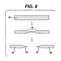
- a stainless steel strip material 76 is rolled down along its length to provide generally concave beveled surfaces 78.
- the rolled down strip material optionally can be heat treated to harden the stainless steel (step not shown) and the strip material separated to provide portions 80, each including a generally concave beveled surface 82.
- Surface 82 is sharpened and separated portion 80 is chopped into razor blade length sections, which are further processed to provide razor blades (steps not shown).
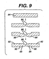
- a stainless steel strip material 84 is rolled down centrally to provide beveled surfaces 86.
- the rolled down strip material is then offset along its length at regions 88 and flattened to provide weakened regions 90.
- the strip material includes blade portions 94 and blade precursor removable portions 92.
- the strip material is separated centrally lengthwise either before or after heat treatment and, after further processing including sharpening of separated beveled surfaces 86, converted into razor blade precursors including razor blade portions and removable portions.
- Razor blade precursors including blade and removable portions are described in U.S. Pat. 6,629,475 , which also is hereby incorporated herein.
- a process line for performing the roll down, offset, and flattening steps in Fig. 9 includes an unwind station 96, a weld station 98, tensioning stations 100 and 108, a roll down station 102, and a winding station 110; these stations were discussed previously in connection with Fig. 5 .
- the process line further includes an offset station 104 and a flattening station 106 subsequent to roll down station 102.
- strip materials are rolled down on two surfaces in the processes shown in Figs. 4-10 , optionally the strip material can be rolled down on only one surface.
- the strip material can be rolled down on only one surface.
- one side can be rolled down (or otherwise pressed) more than the other.
- one rolled down (or otherwise pressed) surface will vary less in thickness from the adjoining strip material than the other rolled down (or otherwise pressed) surface of the strip material.
- any of the above procedures can be combined with the procedures for thinning, and optionally for controlling the tension.
- one optional procedure includes (1) rolling down (or otherwise pressing) the strip material (optionally in combination with offsetting and/or flattening) while also thinning the strip material, (2) adjusting the tension on the strip material to compensate for the added length of the strip material resulting from thinning, and (3) rolling down the strip material a second time (again optionally combined with offsetting and/or flattening).
- the tension in the strip material optionally also may be adjusted after step (3), if this step also significantly thins the strip material.
- rolling down decreases the thickness of approximately the entire blade edge region of the strip material
- rolling down (or other form of pressing) can be used to reduce the thickness of only a portion of the blade edge region.
Landscapes
- Engineering & Computer Science (AREA)
- Mechanical Engineering (AREA)
- Life Sciences & Earth Sciences (AREA)
- Forests & Forestry (AREA)
- Heat Treatment Of Sheet Steel (AREA)
- Bending Of Plates, Rods, And Pipes (AREA)
- Dry Shavers And Clippers (AREA)
- Punching Or Piercing (AREA)
- Milling, Broaching, Filing, Reaming, And Others (AREA)
- Perforating, Stamping-Out Or Severing By Means Other Than Cutting (AREA)
- Forging (AREA)
- Seasonings (AREA)
Claims (9)
- Procédé de fabrication de lames de rasoir incluant des arêtes de lame provenant d'un matériau de bande (30) ayant une région d'arête de lame s'étendant longitudinalement (31) qui est convertie en les arêtes de lame durant le procédé, le procédé comprenant :(a) une pression d'une partie de la région d'arête de lame s'étendant longitudinalement (31) pour fournir à la partie une épaisseur qui est inférieure à l'épaisseur du matériau de bande attenant à la région d'arête de lame s'étendant longitudinalement ; et(c) une conversion du matériau de bande provenant de l'étape (a) en les lames de rasoir incluant les arêtes de lame,
le procédé étant caractérisé en ce qu'il comprend en outre :(b) un décalage d'une première partie s'étendant longitudinalement du matériau de bande à partir d'une deuxième partie s'étendant longitudinalement du matériau de bande. - Procédé selon la revendication 1, dans lequel l'étape (a) fournit à la région d'arête de lame s'étendant longitudinalement (31) une surface supérieure biseautée et une surface inférieure biseautée (36).
- Procédé selon la revendication 1, dans lequel l'étape (a) fournit à la région d'arête de lame s'étendant longitudinalement une surface inférieure biseautée généralement linéaire (58) et une surface inférieure généralement biseautée (58).
- Procédé selon la revendication 1, dans lequel l'étape (a) fournit à la région d'arête de lame s'étendant longitudinalement une surface supérieure biseautée généralement concave (78) et une surface inférieure biseautée généralement concave (78).
- Procédé selon la revendication 1, dans lequel l'étape (a) fournit à la région d'arête de lame s'étendant longitudinalement une surface inférieure biseautée généralement convexe (70) et une surface inférieure biseautée généralement convexe (70).
- Procédé selon l'une quelconque des revendications précédentes, dans lequel la région d'arête de lame s'étendant longitudinalement est située approximativement au centre sur le matériau de bande, le matériau de bande ayant une surface supérieure et une surface inférieure, et dans lequel l'étape (a) fournit à la région s'étendant longitudinalement des surfaces biseautées adjacentes sur la surface supérieure et des surfaces de biseau adjacentes sur la surface inférieure.
- Procédé selon l'une quelconque des revendications 1 à 5, dans lequel la région d'arête de lame s'étendant longitudinalement est située sur une extrémité latérale du matériau de bande.
- Procédé selon l'une quelconque des revendications précédentes, comprenant en outre :(a) une mise en contact d'une surface de la région d'arête de lame s'étendant longitudinalement (31) avec au moins un rouleau pour fournir une surface biseautée, et(b) une conversion du matériau de bande provenant de l'étape (a) en les lames de rasoir incluant les arêtes de lame.
- Procédé selon l'une quelconque des revendications précédentes, comprenant en outre
une conversion du matériau de bande incluant une région d'arête de lame s'étendant longitudinalement qui devient ultérieurement des arêtes de lame sur les lames de rasoir et a une épaisseur qui est inférieure à l'épaisseur du matériau de bande attenant à la région d'arête de lame s'étendant longitudinalement dans les lames de rasoir incluant les arêtes de lame.
Priority Applications (1)
| Application Number | Priority Date | Filing Date | Title |
|---|---|---|---|
| PL06809670T PL1940568T3 (pl) | 2005-10-26 | 2006-10-23 | Sposób wytwarzania ostrzy maszynki do golenia |
Applications Claiming Priority (2)
| Application Number | Priority Date | Filing Date | Title |
|---|---|---|---|
| US11/259,528 US8061237B2 (en) | 2005-10-26 | 2005-10-26 | Manufacturing razor blades |
| PCT/IB2006/053892 WO2007049216A1 (fr) | 2005-10-26 | 2006-10-23 | Procede de fabrication de lames de rasoir |
Publications (2)
| Publication Number | Publication Date |
|---|---|
| EP1940568A1 EP1940568A1 (fr) | 2008-07-09 |
| EP1940568B1 true EP1940568B1 (fr) | 2010-08-04 |
Family
ID=37771067
Family Applications (1)
| Application Number | Title | Priority Date | Filing Date |
|---|---|---|---|
| EP06809670A Active EP1940568B1 (fr) | 2005-10-26 | 2006-10-23 | Procede de fabrication de lames de rasoir |
Country Status (12)
| Country | Link |
|---|---|
| US (1) | US8061237B2 (fr) |
| EP (1) | EP1940568B1 (fr) |
| JP (1) | JP5191897B2 (fr) |
| KR (1) | KR101033727B1 (fr) |
| CN (1) | CN101296764B (fr) |
| AT (1) | ATE476268T1 (fr) |
| BR (1) | BRPI0617895A2 (fr) |
| CA (1) | CA2626871A1 (fr) |
| DE (1) | DE602006015987D1 (fr) |
| PL (1) | PL1940568T3 (fr) |
| RU (1) | RU2383406C2 (fr) |
| WO (1) | WO2007049216A1 (fr) |
Families Citing this family (12)
| Publication number | Priority date | Publication date | Assignee | Title |
|---|---|---|---|---|
| US7578217B2 (en) * | 2005-10-26 | 2009-08-25 | The Gillette Company | Manufacturing razor blades |
| US7823272B2 (en) * | 2006-11-14 | 2010-11-02 | The Gillette Company | Systems for producing assemblies |
| AU2008319174B2 (en) * | 2007-10-29 | 2014-07-24 | Edgewell Personal Care Brands, Llc | Razor blade and method of manufacture |
| KR101055684B1 (ko) * | 2009-02-11 | 2011-08-09 | 주식회사 도루코 | 일체형 면도날 및 이를 이용한 면도기 카트리지 |
| US8635755B2 (en) * | 2010-04-13 | 2014-01-28 | Daetwyler Swisstec Ag | Method for producing doctor blades |
| WO2012158141A1 (fr) * | 2011-05-13 | 2012-11-22 | Eveready Battery Company, Inc | Supports de lame de rasoir |
| US11020108B2 (en) | 2015-03-02 | 2021-06-01 | Mound Laser & Photonics Center, Inc. | Needle with rounded edge |
| US11285631B2 (en) | 2015-03-02 | 2022-03-29 | Mound Laser & Photonics Center, Inc. | Chemically sharpening blades |
| US10500748B2 (en) | 2015-03-02 | 2019-12-10 | Hutchinson Technology Incorporated | Chemically sharpened blades |
| JP6629456B2 (ja) * | 2016-02-23 | 2020-01-15 | コーニンクレッカ フィリップス エヌ ヴェKoninklijke Philips N.V. | 亀裂なしに金属ブランクを折り曲げる方法 |
| CN108856296A (zh) * | 2018-06-20 | 2018-11-23 | 陈明友 | 刀坯轧制工艺 |
| WO2021055769A1 (fr) * | 2019-09-18 | 2021-03-25 | Massachusetts Institute Of Technology | Systèmes, compositions, et procédés de production de bords tranchants |
Family Cites Families (28)
| Publication number | Priority date | Publication date | Assignee | Title |
|---|---|---|---|---|
| US1370381A (en) * | 1914-03-16 | 1921-03-01 | John P Tarbox | Machine for forming razor-blades |
| US1734554A (en) * | 1928-01-28 | 1929-11-05 | American Safety Razor Corp | Method of making narrow-gauge razor blades |
| US2053375A (en) * | 1933-06-03 | 1936-09-08 | American Fork & Hoe Co | Bar making process |
| US2226948A (en) * | 1936-01-11 | 1940-12-31 | Simons Abraham | Method of rolling |
| US2275517A (en) * | 1941-07-01 | 1942-03-10 | Harold C Fay | Safety razor |
| GB548647A (en) | 1941-11-10 | 1942-10-19 | George Theophilus Money | Improvements in and relating to safety razor blades |
| US2593307A (en) * | 1949-04-18 | 1952-04-15 | Jacobsen Edwin | Safety razor |
| FR1331455A (fr) | 1962-05-21 | 1963-07-05 | Loire Atel Forges | Profils doubles-biseaux de coutellerie, procédé pour leur mise en oeuvre et outil de découpe utilisé |
| US3279283A (en) * | 1965-03-22 | 1966-10-18 | Burnie J Craig | Method of making razor blades |
| GB1163222A (en) | 1967-06-19 | 1969-09-04 | Gillette Industries Ltd | Improvements relating to Safety Razors |
| US3847683A (en) * | 1971-11-01 | 1974-11-12 | Gillette Co | Processes for producing novel steels |
| JPS5296477A (en) * | 1976-02-09 | 1977-08-13 | Teizou Maeda | Slitting method and device therefor |
| US4370910A (en) * | 1980-12-30 | 1983-02-01 | Nippon Steel Corporation | Method and apparatus for cutting metal pieces into narrower widths |
| US4608782A (en) * | 1985-05-17 | 1986-09-02 | The Gillette Company | Method and apparatus for sharpening razor blades |
| JPH01154801A (ja) | 1987-12-09 | 1989-06-16 | Feather Kogyo Kk | 替刃用材の圧延成形方法 |
| US5458025A (en) * | 1994-03-17 | 1995-10-17 | The Gillette Company | Razor blade manufacture |
| JPH09510401A (ja) * | 1994-03-17 | 1997-10-21 | ザ、ジレット、カンパニー | カミソリ刃の製造 |
| US5600804A (en) * | 1995-03-23 | 1997-02-04 | Canon Kabushiki Kaisha | Shared RAM access arrangement |
| US5701788A (en) * | 1995-11-15 | 1997-12-30 | The Gillette Company | Razor blade manufacture |
| US5661907A (en) * | 1996-04-10 | 1997-09-02 | The Gillette Company | Razor blade assembly |
| GB9616402D0 (en) | 1996-08-05 | 1996-09-25 | Gillette Co | Safety razors |
| US6684513B1 (en) * | 2000-02-29 | 2004-02-03 | The Gillette Company | Razor blade technology |
| JP3534033B2 (ja) * | 2000-02-29 | 2004-06-07 | 日産自動車株式会社 | 積層式金属ベルト用リングとその製造方法 |
| US6629475B1 (en) | 2000-07-18 | 2003-10-07 | The Gillette Company | Razor blade |
| US7117925B2 (en) * | 2000-09-29 | 2006-10-10 | Nucor Corporation | Production of thin steel strip |
| DE10143680C1 (de) * | 2001-08-30 | 2003-05-08 | Leibniz Inst Fuer Festkoerper | Verfahren zur Herstellung von Metallbändern mit hochgradiger Würfeltextur |
| US8607667B2 (en) * | 2005-10-26 | 2013-12-17 | The Gillette Company | Manufacturing razor blades |
| US7578217B2 (en) * | 2005-10-26 | 2009-08-25 | The Gillette Company | Manufacturing razor blades |
-
2005
- 2005-10-26 US US11/259,528 patent/US8061237B2/en active Active
-
2006
- 2006-10-23 JP JP2008536197A patent/JP5191897B2/ja not_active Expired - Fee Related
- 2006-10-23 CA CA002626871A patent/CA2626871A1/fr not_active Abandoned
- 2006-10-23 RU RU2008110404/02A patent/RU2383406C2/ru active
- 2006-10-23 BR BRPI0617895-2A patent/BRPI0617895A2/pt not_active IP Right Cessation
- 2006-10-23 PL PL06809670T patent/PL1940568T3/pl unknown
- 2006-10-23 AT AT06809670T patent/ATE476268T1/de not_active IP Right Cessation
- 2006-10-23 KR KR1020087009824A patent/KR101033727B1/ko not_active Expired - Fee Related
- 2006-10-23 EP EP06809670A patent/EP1940568B1/fr active Active
- 2006-10-23 CN CN2006800400277A patent/CN101296764B/zh active Active
- 2006-10-23 DE DE602006015987T patent/DE602006015987D1/de active Active
- 2006-10-23 WO PCT/IB2006/053892 patent/WO2007049216A1/fr not_active Ceased
Also Published As
| Publication number | Publication date |
|---|---|
| ATE476268T1 (de) | 2010-08-15 |
| BRPI0617895A2 (pt) | 2011-08-09 |
| KR101033727B1 (ko) | 2011-05-09 |
| KR20080056740A (ko) | 2008-06-23 |
| JP5191897B2 (ja) | 2013-05-08 |
| JP2009512487A (ja) | 2009-03-26 |
| US20070163390A1 (en) | 2007-07-19 |
| PL1940568T3 (pl) | 2011-01-31 |
| US8061237B2 (en) | 2011-11-22 |
| WO2007049216A1 (fr) | 2007-05-03 |
| RU2383406C2 (ru) | 2010-03-10 |
| CN101296764A (zh) | 2008-10-29 |
| CN101296764B (zh) | 2013-03-27 |
| EP1940568A1 (fr) | 2008-07-09 |
| CA2626871A1 (fr) | 2007-05-03 |
| RU2008110404A (ru) | 2009-12-10 |
| DE602006015987D1 (de) | 2010-09-16 |
Similar Documents
| Publication | Publication Date | Title |
|---|---|---|
| EP1940568B1 (fr) | Procede de fabrication de lames de rasoir | |
| EP2004365B1 (fr) | Éléments coupants pour rasoirs | |
| US6629475B1 (en) | Razor blade | |
| CN101421061A (zh) | 用于剃刀的切割构件 | |
| US8607667B2 (en) | Manufacturing razor blades | |
| US7578217B2 (en) | Manufacturing razor blades | |
| EP2203282B1 (fr) | Procédé de fabrication de lames de rasoir | |
| JP6850418B2 (ja) | 金属条の製造方法 | |
| JP2825442B2 (ja) | マッシャロール装置およびその運転方法 | |
| JP2020121317A (ja) | 鋼帯のサイドトリマー、鋼帯の剪断装置、鋼帯の剪断方法及び鋼帯の製造方法 | |
| JPH0839503A (ja) | のこ身の製法及びのこ身 | |
| JPH08105761A (ja) | 金属帯 | |
| JP2006281227A (ja) | 狭幅金属帯のエッジラウンド加工方法 | |
| JPH08117852A (ja) | 金属帯 |
Legal Events
| Date | Code | Title | Description |
|---|---|---|---|
| PUAI | Public reference made under article 153(3) epc to a published international application that has entered the european phase |
Free format text: ORIGINAL CODE: 0009012 |
|
| 17P | Request for examination filed |
Effective date: 20080312 |
|
| AK | Designated contracting states |
Kind code of ref document: A1 Designated state(s): AT BE BG CH CY CZ DE DK EE ES FI FR GB GR HU IE IS IT LI LT LU LV MC NL PL PT RO SE SI SK TR |
|
| 17Q | First examination report despatched |
Effective date: 20081117 |
|
| GRAP | Despatch of communication of intention to grant a patent |
Free format text: ORIGINAL CODE: EPIDOSNIGR1 |
|
| GRAS | Grant fee paid |
Free format text: ORIGINAL CODE: EPIDOSNIGR3 |
|
| GRAA | (expected) grant |
Free format text: ORIGINAL CODE: 0009210 |
|
| AK | Designated contracting states |
Kind code of ref document: B1 Designated state(s): AT BE BG CH CY CZ DE DK EE ES FI FR GB GR HU IE IS IT LI LT LU LV MC NL PL PT RO SE SI SK TR |
|
| REG | Reference to a national code |
Ref country code: GB Ref legal event code: FG4D |
|
| REG | Reference to a national code |
Ref country code: CH Ref legal event code: EP |
|
| REG | Reference to a national code |
Ref country code: IE Ref legal event code: FG4D |
|
| REF | Corresponds to: |
Ref document number: 602006015987 Country of ref document: DE Date of ref document: 20100916 Kind code of ref document: P |
|
| REG | Reference to a national code |
Ref country code: GR Ref legal event code: EP Ref document number: 20100402285 Country of ref document: GR |
|
| REG | Reference to a national code |
Ref country code: NL Ref legal event code: VDEP Effective date: 20100804 |
|
| LTIE | Lt: invalidation of european patent or patent extension |
Effective date: 20100804 |
|
| PG25 | Lapsed in a contracting state [announced via postgrant information from national office to epo] |
Ref country code: LT Free format text: LAPSE BECAUSE OF FAILURE TO SUBMIT A TRANSLATION OF THE DESCRIPTION OR TO PAY THE FEE WITHIN THE PRESCRIBED TIME-LIMIT Effective date: 20100804 Ref country code: AT Free format text: LAPSE BECAUSE OF FAILURE TO SUBMIT A TRANSLATION OF THE DESCRIPTION OR TO PAY THE FEE WITHIN THE PRESCRIBED TIME-LIMIT Effective date: 20100804 Ref country code: NL Free format text: LAPSE BECAUSE OF FAILURE TO SUBMIT A TRANSLATION OF THE DESCRIPTION OR TO PAY THE FEE WITHIN THE PRESCRIBED TIME-LIMIT Effective date: 20100804 Ref country code: FI Free format text: LAPSE BECAUSE OF FAILURE TO SUBMIT A TRANSLATION OF THE DESCRIPTION OR TO PAY THE FEE WITHIN THE PRESCRIBED TIME-LIMIT Effective date: 20100804 |
|
| REG | Reference to a national code |
Ref country code: PL Ref legal event code: T3 |
|
| PG25 | Lapsed in a contracting state [announced via postgrant information from national office to epo] |
Ref country code: PT Free format text: LAPSE BECAUSE OF FAILURE TO SUBMIT A TRANSLATION OF THE DESCRIPTION OR TO PAY THE FEE WITHIN THE PRESCRIBED TIME-LIMIT Effective date: 20101206 Ref country code: SI Free format text: LAPSE BECAUSE OF FAILURE TO SUBMIT A TRANSLATION OF THE DESCRIPTION OR TO PAY THE FEE WITHIN THE PRESCRIBED TIME-LIMIT Effective date: 20100804 Ref country code: CY Free format text: LAPSE BECAUSE OF FAILURE TO SUBMIT A TRANSLATION OF THE DESCRIPTION OR TO PAY THE FEE WITHIN THE PRESCRIBED TIME-LIMIT Effective date: 20100804 Ref country code: BG Free format text: LAPSE BECAUSE OF FAILURE TO SUBMIT A TRANSLATION OF THE DESCRIPTION OR TO PAY THE FEE WITHIN THE PRESCRIBED TIME-LIMIT Effective date: 20101104 Ref country code: IS Free format text: LAPSE BECAUSE OF FAILURE TO SUBMIT A TRANSLATION OF THE DESCRIPTION OR TO PAY THE FEE WITHIN THE PRESCRIBED TIME-LIMIT Effective date: 20101204 |
|
| PG25 | Lapsed in a contracting state [announced via postgrant information from national office to epo] |
Ref country code: LV Free format text: LAPSE BECAUSE OF FAILURE TO SUBMIT A TRANSLATION OF THE DESCRIPTION OR TO PAY THE FEE WITHIN THE PRESCRIBED TIME-LIMIT Effective date: 20100804 Ref country code: SE Free format text: LAPSE BECAUSE OF FAILURE TO SUBMIT A TRANSLATION OF THE DESCRIPTION OR TO PAY THE FEE WITHIN THE PRESCRIBED TIME-LIMIT Effective date: 20100804 Ref country code: BE Free format text: LAPSE BECAUSE OF FAILURE TO SUBMIT A TRANSLATION OF THE DESCRIPTION OR TO PAY THE FEE WITHIN THE PRESCRIBED TIME-LIMIT Effective date: 20100804 |
|
| PG25 | Lapsed in a contracting state [announced via postgrant information from national office to epo] |
Ref country code: DK Free format text: LAPSE BECAUSE OF FAILURE TO SUBMIT A TRANSLATION OF THE DESCRIPTION OR TO PAY THE FEE WITHIN THE PRESCRIBED TIME-LIMIT Effective date: 20100804 |
|
| PG25 | Lapsed in a contracting state [announced via postgrant information from national office to epo] |
Ref country code: SK Free format text: LAPSE BECAUSE OF FAILURE TO SUBMIT A TRANSLATION OF THE DESCRIPTION OR TO PAY THE FEE WITHIN THE PRESCRIBED TIME-LIMIT Effective date: 20100804 Ref country code: IT Free format text: LAPSE BECAUSE OF FAILURE TO SUBMIT A TRANSLATION OF THE DESCRIPTION OR TO PAY THE FEE WITHIN THE PRESCRIBED TIME-LIMIT Effective date: 20100804 Ref country code: MC Free format text: LAPSE BECAUSE OF NON-PAYMENT OF DUE FEES Effective date: 20101031 Ref country code: CZ Free format text: LAPSE BECAUSE OF FAILURE TO SUBMIT A TRANSLATION OF THE DESCRIPTION OR TO PAY THE FEE WITHIN THE PRESCRIBED TIME-LIMIT Effective date: 20100804 Ref country code: EE Free format text: LAPSE BECAUSE OF FAILURE TO SUBMIT A TRANSLATION OF THE DESCRIPTION OR TO PAY THE FEE WITHIN THE PRESCRIBED TIME-LIMIT Effective date: 20100804 Ref country code: RO Free format text: LAPSE BECAUSE OF FAILURE TO SUBMIT A TRANSLATION OF THE DESCRIPTION OR TO PAY THE FEE WITHIN THE PRESCRIBED TIME-LIMIT Effective date: 20100804 |
|
| REG | Reference to a national code |
Ref country code: CH Ref legal event code: PL |
|
| PLBE | No opposition filed within time limit |
Free format text: ORIGINAL CODE: 0009261 |
|
| STAA | Information on the status of an ep patent application or granted ep patent |
Free format text: STATUS: NO OPPOSITION FILED WITHIN TIME LIMIT |
|
| PG25 | Lapsed in a contracting state [announced via postgrant information from national office to epo] |
Ref country code: ES Free format text: LAPSE BECAUSE OF FAILURE TO SUBMIT A TRANSLATION OF THE DESCRIPTION OR TO PAY THE FEE WITHIN THE PRESCRIBED TIME-LIMIT Effective date: 20101115 |
|
| 26N | No opposition filed |
Effective date: 20110506 |
|
| PG25 | Lapsed in a contracting state [announced via postgrant information from national office to epo] |
Ref country code: LI Free format text: LAPSE BECAUSE OF NON-PAYMENT OF DUE FEES Effective date: 20101031 Ref country code: CH Free format text: LAPSE BECAUSE OF NON-PAYMENT OF DUE FEES Effective date: 20101031 |
|
| REG | Reference to a national code |
Ref country code: DE Ref legal event code: R097 Ref document number: 602006015987 Country of ref document: DE Effective date: 20110506 |
|
| PG25 | Lapsed in a contracting state [announced via postgrant information from national office to epo] |
Ref country code: IE Free format text: LAPSE BECAUSE OF NON-PAYMENT OF DUE FEES Effective date: 20101023 |
|
| PGFP | Annual fee paid to national office [announced via postgrant information from national office to epo] |
Ref country code: FR Payment date: 20111005 Year of fee payment: 6 |
|
| PG25 | Lapsed in a contracting state [announced via postgrant information from national office to epo] |
Ref country code: HU Free format text: LAPSE BECAUSE OF FAILURE TO SUBMIT A TRANSLATION OF THE DESCRIPTION OR TO PAY THE FEE WITHIN THE PRESCRIBED TIME-LIMIT Effective date: 20110205 Ref country code: LU Free format text: LAPSE BECAUSE OF NON-PAYMENT OF DUE FEES Effective date: 20101023 |
|
| REG | Reference to a national code |
Ref country code: FR Ref legal event code: ST Effective date: 20130628 |
|
| PG25 | Lapsed in a contracting state [announced via postgrant information from national office to epo] |
Ref country code: FR Free format text: LAPSE BECAUSE OF NON-PAYMENT OF DUE FEES Effective date: 20121031 |
|
| PGFP | Annual fee paid to national office [announced via postgrant information from national office to epo] |
Ref country code: PL Payment date: 20181015 Year of fee payment: 13 |
|
| PGFP | Annual fee paid to national office [announced via postgrant information from national office to epo] |
Ref country code: IT Payment date: 20190225 Year of fee payment: 6 |
|
| PG25 | Lapsed in a contracting state [announced via postgrant information from national office to epo] |
Ref country code: PL Free format text: LAPSE BECAUSE OF NON-PAYMENT OF DUE FEES Effective date: 20191023 |
|
| PG25 | Lapsed in a contracting state [announced via postgrant information from national office to epo] |
Ref country code: TR Free format text: LAPSE BECAUSE OF NON-PAYMENT OF DUE FEES Effective date: 20191023 |
|
| PGFP | Annual fee paid to national office [announced via postgrant information from national office to epo] |
Ref country code: GR Payment date: 20220914 Year of fee payment: 17 |
|
| P01 | Opt-out of the competence of the unified patent court (upc) registered |
Effective date: 20230430 |
|
| PG25 | Lapsed in a contracting state [announced via postgrant information from national office to epo] |
Ref country code: GR Free format text: LAPSE BECAUSE OF NON-PAYMENT OF DUE FEES Effective date: 20240515 |
|
| PG25 | Lapsed in a contracting state [announced via postgrant information from national office to epo] |
Ref country code: GR Free format text: LAPSE BECAUSE OF NON-PAYMENT OF DUE FEES Effective date: 20240515 |
|
| PGFP | Annual fee paid to national office [announced via postgrant information from national office to epo] |
Ref country code: GB Payment date: 20240829 Year of fee payment: 19 |
|
| PGFP | Annual fee paid to national office [announced via postgrant information from national office to epo] |
Ref country code: DE Payment date: 20240904 Year of fee payment: 19 |