EP1940657B1 - Siege de vehicule automobile dote d'airbags lateraux pour le thorax et le bassin disposes sur l'encadrement du siege - Google Patents
Siege de vehicule automobile dote d'airbags lateraux pour le thorax et le bassin disposes sur l'encadrement du siege Download PDFInfo
- Publication number
- EP1940657B1 EP1940657B1 EP06806338A EP06806338A EP1940657B1 EP 1940657 B1 EP1940657 B1 EP 1940657B1 EP 06806338 A EP06806338 A EP 06806338A EP 06806338 A EP06806338 A EP 06806338A EP 1940657 B1 EP1940657 B1 EP 1940657B1
- Authority
- EP
- European Patent Office
- Prior art keywords
- gas
- vehicle seat
- airbag
- sack
- seat
- Prior art date
- Legal status (The legal status is an assumption and is not a legal conclusion. Google has not performed a legal analysis and makes no representation as to the accuracy of the status listed.)
- Not-in-force
Links
Images
Classifications
-
- B—PERFORMING OPERATIONS; TRANSPORTING
- B60—VEHICLES IN GENERAL
- B60R—VEHICLES, VEHICLE FITTINGS, OR VEHICLE PARTS, NOT OTHERWISE PROVIDED FOR
- B60R21/00—Arrangements or fittings on vehicles for protecting or preventing injuries to occupants or pedestrians in case of accidents or other traffic risks
- B60R21/02—Occupant safety arrangements or fittings, e.g. crash pads
- B60R21/16—Inflatable occupant restraints or confinements designed to inflate upon impact or impending impact, e.g. air bags
- B60R21/20—Arrangements for storing inflatable members in their non-use or deflated condition; Arrangement or mounting of air bag modules or components
- B60R21/207—Arrangements for storing inflatable members in their non-use or deflated condition; Arrangement or mounting of air bag modules or components in vehicle seats
-
- B—PERFORMING OPERATIONS; TRANSPORTING
- B60—VEHICLES IN GENERAL
- B60R—VEHICLES, VEHICLE FITTINGS, OR VEHICLE PARTS, NOT OTHERWISE PROVIDED FOR
- B60R21/00—Arrangements or fittings on vehicles for protecting or preventing injuries to occupants or pedestrians in case of accidents or other traffic risks
- B60R21/02—Occupant safety arrangements or fittings, e.g. crash pads
- B60R21/16—Inflatable occupant restraints or confinements designed to inflate upon impact or impending impact, e.g. air bags
- B60R21/20—Arrangements for storing inflatable members in their non-use or deflated condition; Arrangement or mounting of air bag modules or components
- B60R21/217—Inflation fluid source retainers, e.g. reaction canisters; Connection of bags, covers, diffusers or inflation fluid sources therewith or together
-
- B—PERFORMING OPERATIONS; TRANSPORTING
- B60—VEHICLES IN GENERAL
- B60R—VEHICLES, VEHICLE FITTINGS, OR VEHICLE PARTS, NOT OTHERWISE PROVIDED FOR
- B60R21/00—Arrangements or fittings on vehicles for protecting or preventing injuries to occupants or pedestrians in case of accidents or other traffic risks
- B60R21/02—Occupant safety arrangements or fittings, e.g. crash pads
- B60R21/16—Inflatable occupant restraints or confinements designed to inflate upon impact or impending impact, e.g. air bags
- B60R21/23—Inflatable members
- B60R21/231—Inflatable members characterised by their shape, construction or spatial configuration
- B60R21/233—Inflatable members characterised by their shape, construction or spatial configuration comprising a plurality of individual compartments; comprising two or more bag-like members, one within the other
- B60R2021/23316—Inner seams, e.g. creating separate compartments or used as tethering means
-
- B—PERFORMING OPERATIONS; TRANSPORTING
- B60—VEHICLES IN GENERAL
- B60R—VEHICLES, VEHICLE FITTINGS, OR VEHICLE PARTS, NOT OTHERWISE PROVIDED FOR
- B60R21/00—Arrangements or fittings on vehicles for protecting or preventing injuries to occupants or pedestrians in case of accidents or other traffic risks
- B60R21/02—Occupant safety arrangements or fittings, e.g. crash pads
- B60R21/16—Inflatable occupant restraints or confinements designed to inflate upon impact or impending impact, e.g. air bags
- B60R21/23—Inflatable members
- B60R21/231—Inflatable members characterised by their shape, construction or spatial configuration
- B60R21/23138—Inflatable members characterised by their shape, construction or spatial configuration specially adapted for side protection
Definitions
- the invention relates to a vehicle seat having a seat surface and a seat back, which has a seat frame covered by a cushion, to which an airbag unit with a folded or rolled gas bag and a gas generator is attached, which is in fluid communication with the gas bag, such a vehicle seat particularly advantageous in a side impact when the airbag deploys between the seat occupant and a vehicle side structure.
- the US 5,651,582 describes a vehicle seat with a seat cushion and a seat back having a frame.
- a molding for receiving the gas generator is formed on a side strut.
- the gas generator is fixed by a bolt on the molding.
- the gas generator is surrounded together with the folded gas bag by a cover which is fixed at a further attachment point to the seat frame.
- a Sollrissnaht allows easy passage of the unfolding airbag forward.
- the EP 940 298 A1 describes an airbag device in a vehicle seat.
- the airbag is disposed on the seat frame within a housing and secured by bolts. After ignition of the gas generator, the airbag unfolds to the front.
- the US 6,279,944 B1 describes an enclosed in a gas generator, which is fixed to a seat frame.
- the airbag unfolds forward and forward next to the seat occupant.
- the JP 2004210049 relates to an airbag disposed below a seat cushion and intended to prevent forward slipping of a vehicle occupant during a frontal impact.
- the airbag is laid flat on a pad below the pad.
- the EP 1 459 942 A1 describes an occupant protection system in which an airbag is arranged below a seat cushion in the knee area. As soon as an excessive delay is measured via sensors, the airbag unfolds and prevents the vehicle occupant from slipping forward.
- the JP 09202204 describes an airbag packaging unit and method for deploying an airbag in which the gas generator is arranged together with the folded airbag in a soft envelope.
- This system of gas generator and folded airbag together with the envelope may also be arranged on a seat back. The determination takes place via bolts of the gas generator.
- the JP 06278513 relates to a device for protection in a rear impact, in which an airbag module is arranged at the back of a seat. A shell surrounds the airbag module.
- the JP 57058533 describes a device in which a wheel drives a crank which places a piston in a reciprocating motion. This piston inflates an airbag located in the back of a seat. This construction can be used together with a seat belt.
- the JP 05310095 describes an airbag module which is attached to the backrest in the rearward direction. Traction cables are arranged at the ends of the airbag and over Pulleys attached to the front seat to adjust the expansion depth of the airbag can.
- the WO 98/56623 describes a method for folding an airbag and an arrangement of such a kind folded airbag on a side frame of a seat back.
- the attachment via three bolts, which are formed on the gas generator.
- the DE 203 06 153 U1 describes a vehicle seat with integrated airbag with a seat and a backrest, wherein the backrest comprises a frame covered with a padding.
- An airbag unit including an inflatable airbag connected to an inflator to inflate the airbag upon activation of the airbag unit is attached to the frame of the seatback so as to be covered by the cushioning.
- the padding of the backrest has a predetermined breaking line, which is arranged with respect to the airbag unit such that the padding is separated along an activation line of the airbag unit along the break line, so that a part of the padding is deflected by the inflating airbag.
- the airbag is attached only via the gas generator to the seat frame.
- the attachment is made via the mounting bolts of the gas generator, with which this is fixed to the seat frame.
- Such attachment has the disadvantage that the unfolded airbag is poorly fixed and thus can deploy in directions in which a suboptimal protective effect for the seat occupant is provided.
- the object of the present invention is to provide an improved vehicle seat which ensures improved guidance of the airbag during inflation and when inflated.
- the vehicle seat according to the invention with a seat surface and a seat back having a seat frame covered by a cushion, to which an airbag unit with a folded or rolled gas bag having a gas inlet and a gas generator is attached to a first attachment point, which is in fluid communication with the gas bag , provides that the gas bag is fixed to the outside of the seat occupant side facing away from the seat frame at a second attachment point, so in addition to the attachment on the gas generator also has a further attachment point, so that the airbag can not swing freely and uncontrollably in the inflated state, wherein the gas generator is arranged on the rear side or the inside of the seat frame and between the gas inlet and the folded or rolled gas bag, a gas guide portion is formed, are provided in the mounting holes of the second attachment point.
- the gas bag has a gas inlet in the region of the gas generator and is fastened there via fastening bolts of the gas generator to the seat frame.
- a gas guide section may be formed, which is fixed positively on the outside of the seat frame. This makes it possible that the gas generator can be mounted at a remote location on the seat frame, without a deficient fixation of the airbag or an uncontrolled deployment during inflation of the airbag occur.
- the gas bag section it is possible to space-savingly arrange the gas generator on the inside of the seat frame taking advantage of a profile design, without the seating comfort suffers.
- the airbag can then be in a folded or rolled state in one place be arranged the seat frame, which is optimal for its protective effect without sacrificing the fixation of the airbag occur. In this way, the generally small space between the side wall of the seat and the seat frame can be reduced to a minimum.
- the rolled-up or folded gas bag can be arranged in a housing, in particular in a soft-deformable envelope, a so-called soft cover, so that the gas bag is largely protected from external influences that can be transmitted through the pad to the gas bag.
- a simple assembly can take place by fixing the covering, for example via clip connections, hook-and-loop fasteners or the like, on the seat frame, so that the covering together with the gas bag can be formed as part of the cushion.
- the fixation of the airbag to the seat frame is done directly and not by the enclosure.
- the fixation is performed on the seat frame to the gas guide portion, which is not housed in the housing.
- fastening holes are formed at the transition from the gas guide section to the rolled-up or folded gas bag, by means of which the gas bag is fixed in a form-fitting manner to the seat frame, for example by means of clips, screws or rivets.
- a fixation of the gas guide section can also be made in a form-fitting manner via a hook-and-loop fastener.
- the gas generator may be arranged on the rear side or the inside of the seat frame. A selection of the mounting location of the gas generator takes place under the aspects of an optimized assembly and minimal comfort degradation for the seat occupant.
- the gas bag is designed as a multi-chamber gas bag, in particular as a thorax-pelvis gas bag, so that these body regions particularly in a side impact
- a separating seam or a separate fabric web to be provided thereon, which divides the gas bag into a plurality of chambers.
- the gas bag can also be designed as an integrally woven component, in which a plurality of chambers, preferably with different volumes, are formed. The separation of the chambers can be continued until immediately before the gas inlet, so extend through the gas guide section to just before the gas generator.
- the gas generator may have a deflector which prevents direct contact of the generated gases within the gas generator with the gas bag fabric in the region of the gas generator. As a result, the durability of the airbag is increased.
- the deflector directs the hot gas generated by the gas generator and accelerates the filling of the gas bag. For rapid filling of the gas bag, it is provided that discharge openings are provided on the gas generator or deflector, which lie directly in front of the inlet openings of the chambers of the gas bag.
- the airbag is rolled or folded in the direction of the seat frame, so that extends in the presence of appropriate sensor data due to an accident or an imminent accident, the airbag in the direction of travel between the vehicle side structure and the seat occupant.
- FIG. 1 shows a part of a vehicle seat 1 with a seat back 2 and a seat cushion 3 in a schematic front view.
- the seat back 2 has a seat frame 4, which is covered by a pad 5 and the seat frame 4 completely surrounds.
- an airbag unit 10 with a rolled airbag 11 and a gas generator 12 is attached on the seat frame 4, on the seat frame 4, an airbag unit 10 with a rolled airbag 11 and a gas generator 12 is attached.
- the gas generator 12 is fixed on the inside of the seat frame 4 via bolts 21 and at the same time places the gas bag 11 on the inside of the seat frame 4.
- the inside of that side of the seat frame 4 is referred to, which faces the vehicle user, the outside refers to that side of the seat frame 4, which faces away from the seat occupant.
- the back As the front of the seat frame 4 that side is called, which points in the normal direction of travel, the back is aligned against the normal direction of travel accordingly.
- the gas bag 11 is guided on the back of the seat frame 4 to the outside and is fixed there at a further attachment point.
- the airbag unit 10 is coupled to unillustrated sensor units that are coupled in the presence of acceleration data suggesting an accident or data about a rapidly approaching subject that suggests an impending accident. Via a pyrotechnic propellant gas is generated in the gas generator 12 12, which is initiated by the gas generator 12 in the folded or rolled-up airbag 11. This occurs due to the increasing volume of the pad to the front and extends between the vehicle side structure, not shown, and the seat occupant, also not shown.
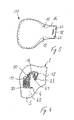
- the airbag 11 may look as it is in the FIG. 2 is shown.
- the gas bag 11 is designed as a two-chamber thorax-pelvis gas bag, wherein the two chambers 17, 18 are formed by a separating seam 19 separated from each other.
- a fabric can be sewn into the airbag 11 to form the two chambers 17, 18.
- the illustrated peripheral seam 19 which connects two fabric blanks with each other, only a parting seam can be present in an integrally woven airbag 11. It is also possible that the multi-chamber design of the airbag 11 is generated from a corresponding weave.
- the gas generator 12 and a dismantled deflector 13 are shown. Attachment bolts 21 and outlet openings 24 are formed on the gas generator 12. About the fastening bolts 21, which pass through recesses 22 in the airbag 11, the airbag 11 is fixed positively at a first location on the seat frame 4. In the immediate vicinity of the recess 22 are gas inlets 17a, 18a, which are opposite the outlet openings 24 and the gas generated by the gas generator 12 in the respective chambers 17, 18 conduct. The gas is passed through a gas guide section 14, which is integrally formed on the airbag 11 or can be sewn thereto, in the chambers 17, 18. The cutting seam 19 extends to just before the gas inlets 17a, 18a.
- the deflector 13 may close the rear exhaust ports 24 or redirect the generated gas so that it also flows into the inlets 17a, 18a.
- mounting holes 15 are provided in the gas bag 11 at the transition of the gas guide portion, which serve for the positive fixing of the airbag at a second location on the seat frame 4. The manner of attachment will be described below.
- FIG. 3 An alternative embodiment of the airbag 11 is in the FIG. 3 represented, in which a Einziggassack 11 is shown.
- the gas inlet 16 is formed in the form of a slot for insertion of the gas generator.
- the attachment is also via the holes 22 at a first location by means of the fastening bolts 21 on the gas generator, not shown.
- two further mounting holes 15 are provided, which serve for further attachment to the seat frame 4.
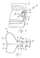
- FIG. 4 is a sectional view in plan view of a possible arrangement of the airbag 11 on the seat frame 4 shown.
- the gas bag 11 is located in a housing 30, which may be formed as a plastic housing or as a deformable soft cover.
- the gas bag 11 rolled up in the soft cover 30 is fastened to the seat frame 4 outside the soft cover 30 via fastening pins 20 which penetrate the fastening openings 15.
- fastening pins 20 which penetrate the fastening openings 15.
- the seat frame 4 has a multi-curved profile. At the back of the profile of the gas generator 12 is fastened via the fastening bolts 21 by means of nuts 23 to the seat frame 4.
- the gas generator 12 is arranged on the side facing away from the seat occupant of the seat back 2.
- the gas guide section 14 is guided on the back and on the outside of the seat frame 4 and fixed in a form-fitting manner on the outside.
- the arrangement shown is a particularly favorable utilization of the space within the seat back 2.
- the gas generator 12 may be disposed within the seat frame 4 and the seat frame profile.
- the gas bag 11 is rolled within the housing 30 in the direction of the seat frame 4, in the present case counterclockwise, in order to allow an as far as possible extended forward deployment along a predetermined tear line 40 formed in the pad 5.
- the pad 5 completely surrounds the airbag 11 and the gas generator 12.
- the gas generator 12 is attached via the attachment means 20 directly to the outside of the seat frame 4 and improves the fixation on the seat frame 4.
- the gas generator can be arranged at different locations, possibly also far away on the seat frame 4 or within the vehicle seat 1.
- Alternative guides and definitions of the airbag 11 and the gas guide portion 14 on the seat frame 4 are also possible.
Landscapes
- Engineering & Computer Science (AREA)
- Mechanical Engineering (AREA)
- Air Bags (AREA)
- Seats For Vehicles (AREA)
- Orthopedics, Nursing, And Contraception (AREA)
Claims (14)
- Siège de véhicule automobile comprenant une surface de siège (3) et un dossier de siège (2) qui présente, recouvert par un rembourrage (5), un châssis de siège (4) auquel est fixée en un premier emplacement de fixation (22, 21) une unité coussin gonflable (10) ayant un sac de gaz (11) replié ou enroulé présentant une admission de gaz (16), et un générateur de gaz (12) qui est relié au sac de gaz (11) par une technique de circulation de fluides, le sac de gaz (11) étant fixé en un deuxième emplacement de fixation (15, 20) à l'extérieur sur la face du châssis de siège (4) opposée à l'utilisateur du siège, caractérisé en ce que le générateur de gaz (12) est agencé du côté arrière ou du côté interne du châssis de siège (4), et il est formé entre l'admission de gaz (16) et le sac de gaz (11) enroulé ou replié un tronçon de guidage de gaz (4) dans lequel sont prévus des trous de fixation (15) du deuxième emplacement de fixation (15, 20).
- Siège de véhicule automobile selon la revendication 1, caractérisé en ce que le sac de gaz (11) présente l'admission de gaz (16) dans la région du générateur de gaz (12) et est fixé au châssis de siège (4) par des boulons de fixation (21) du générateur de gaz (12).
- Siège de véhicule automobile selon la revendication 1 ou 2, caractérisé en ce que le tronçon de guidage de gaz (14) est fixé à la face externe du châssis de siège (4) par conjugaison de forme.
- Siège de véhicule automobile selon l'une des revendications précédentes, caractérisé en ce que le sac de gaz (11) enroulé ou replié est agencé dans un logement (30), en particulier une enveloppe souple déformable.
- Siège de véhicule automobile selon la revendication 4, caractérisé en ce que le tronçon de guidage de gaz (14) n'est pas logé dans le logement (30).
- Siège de véhicule automobile selon l'une des revendications 3 à 5, caractérisé en ce que des trous de fixation (15) grâce auxquels le sac de gaz (11) est directement fixé au châssis de siège (4) sont formés à la jonction du tronçon de guidage de gaz (14) vers le sac de gaz (11) enroulé ou replié.
- Siège de véhicule automobile selon l'une des revendications précédentes, caractérisé en ce que le tronçon de guidage de gaz (14) va du côté interne du châssis de siège (4), le long du côté avant ou du côté arrière, jusqu'au côté externe.
- Siège de véhicule automobile selon l'une des revendications précédentes, caractérisé en ce que le sac de gaz (11) est réalisé sous la forme d'un sac de gaz à plusieurs chambres.
- Siège de véhicule automobile selon la revendication 8, caractérisé en ce que le sac de gaz (11) est réalisé sous la forme d'un sac de gaz thorax-pelvis.
- Siège de véhicule automobile selon la revendication 8 ou 9, caractérisé en ce que le sac de gaz (11) est subdivisé en plusieurs chambres (17, 18) par une couture de séparation (19) ou par une bande de tissu séparé.
- Siège de véhicule automobile selon la revendication 10, caractérisé en ce que la séparation des chambres (17, 18) se poursuit jusque devant l'admission de gaz (16).
- Siège de véhicule automobile selon l'une des revendications précédentes, caractérisé en ce que le générateur de gaz (12) présente un déflecteur (13) qui empêche un contact direct des gaz produits avec le tissu du sac de gaz près du générateur de gaz (12).
- Siège de véhicule automobile selon l'une des revendications 8 à 12, caractérisé en ce que des ouvertures de départ de gaz (24) sont prévues sur le générateur de gaz (12) ou le déflecteur, qui se trouvent devant les ouvertures d'admission (17a, 18a) des chambres (17, 18) du sac de gaz (11).
- Siège de véhicule automobile selon l'une des revendications précédentes, caractérisé en ce que le sac de gaz (11) est enroulé ou replié dans la direction du châssis de siège (4).
Applications Claiming Priority (2)
| Application Number | Priority Date | Filing Date | Title |
|---|---|---|---|
| DE102005051171A DE102005051171B4 (de) | 2005-10-24 | 2005-10-24 | Fahrzeugsitz |
| PCT/EP2006/010008 WO2007048527A1 (fr) | 2005-10-24 | 2006-10-17 | Siege de vehicule automobile dote d'airbags lateraux pour le thorax et le bassin disposes sur l'encadrement du siege |
Publications (2)
| Publication Number | Publication Date |
|---|---|
| EP1940657A1 EP1940657A1 (fr) | 2008-07-09 |
| EP1940657B1 true EP1940657B1 (fr) | 2010-11-24 |
Family
ID=37685111
Family Applications (1)
| Application Number | Title | Priority Date | Filing Date |
|---|---|---|---|
| EP06806338A Not-in-force EP1940657B1 (fr) | 2005-10-24 | 2006-10-17 | Siege de vehicule automobile dote d'airbags lateraux pour le thorax et le bassin disposes sur l'encadrement du siege |
Country Status (4)
| Country | Link |
|---|---|
| EP (1) | EP1940657B1 (fr) |
| AT (1) | ATE489266T1 (fr) |
| DE (2) | DE102005051171B4 (fr) |
| WO (1) | WO2007048527A1 (fr) |
Families Citing this family (5)
| Publication number | Priority date | Publication date | Assignee | Title |
|---|---|---|---|---|
| DE102007045552A1 (de) * | 2007-09-24 | 2009-04-02 | Autoliv Development Ab | Kraftfahrzeugsitz mit Sicherheitseinrichtung |
| EP2746112B1 (fr) * | 2012-12-18 | 2016-10-26 | Autoliv Development AB | Unité d'airbag |
| DE102015016347A1 (de) | 2015-12-17 | 2017-06-22 | Autoliv Development Ab | Airbagvorrichtung für ein Kraftfahrzeug, sowie Airbagkissen für eine Airbagvorrichtung |
| US9688232B1 (en) * | 2016-04-05 | 2017-06-27 | Ford Global Technologies, Llc | Air bag system for rear seat center occupant protection |
| FR3129334B1 (fr) | 2021-11-19 | 2026-04-24 | Faurecia Sieges Dautomobile | Dossier de siège de véhicule muni d’un dispositif de coussin gonflable de sécurité et procédé d’assemblage d’un tel dossier |
Family Cites Families (13)
| Publication number | Priority date | Publication date | Assignee | Title |
|---|---|---|---|---|
| JPS5758533A (en) * | 1980-09-27 | 1982-04-08 | Ebisu Shoten:Kk | Passenger protecting apparatus for car |
| JPH05310095A (ja) * | 1992-05-11 | 1993-11-22 | Nissan Motor Co Ltd | 自動車等における乗員保護装置 |
| JP3144134B2 (ja) * | 1993-03-26 | 2001-03-12 | 日産自動車株式会社 | 背凭れ背面衝撃吸収装置 |
| US5651582A (en) * | 1994-12-20 | 1997-07-29 | Ikeda Bussan Co., Ltd. | Vehicular seat with side air-bag |
| US5628527A (en) * | 1996-01-25 | 1997-05-13 | Morton International, Inc. | Cover/director for air bag |
| DE19635495A1 (de) * | 1996-09-02 | 1998-03-05 | Pars Passive Rueckhaltesysteme | Rückhalteeinrichtung für einen Seitenairbag |
| US5899490A (en) * | 1997-06-13 | 1999-05-04 | Breed Automotive Technology, Inc. | Method of folding an air bag |
| WO1999015366A1 (fr) * | 1997-09-19 | 1999-04-01 | Nissan Motor Co., Ltd. | Dispositif d'airbag |
| DE19813832C2 (de) * | 1998-03-20 | 2003-10-23 | Takata Petri Ag | Gassack für ein Airbagmodul |
| US6279944B1 (en) * | 1998-10-06 | 2001-08-28 | Breed Automotive Technology, Inc. | Air bag with diverter and expanded volume chamber |
| JP4165217B2 (ja) * | 2002-12-27 | 2008-10-15 | タカタ株式会社 | 乗員保護装置 |
| GB2397047B (en) * | 2003-01-10 | 2006-02-22 | Autoliv Development Ab | Improvements in or relating to vehicle air-seats and air-bag units |
| JP4269826B2 (ja) * | 2003-03-12 | 2009-05-27 | タカタ株式会社 | 乗員保護装置 |
-
2005
- 2005-10-24 DE DE102005051171A patent/DE102005051171B4/de not_active Expired - Fee Related
-
2006
- 2006-10-17 DE DE502006008401T patent/DE502006008401D1/de active Active
- 2006-10-17 EP EP06806338A patent/EP1940657B1/fr not_active Not-in-force
- 2006-10-17 WO PCT/EP2006/010008 patent/WO2007048527A1/fr not_active Ceased
- 2006-10-17 AT AT06806338T patent/ATE489266T1/de active
Also Published As
| Publication number | Publication date |
|---|---|
| WO2007048527A1 (fr) | 2007-05-03 |
| DE102005051171B4 (de) | 2011-05-05 |
| EP1940657A1 (fr) | 2008-07-09 |
| ATE489266T1 (de) | 2010-12-15 |
| DE102005051171A1 (de) | 2007-04-26 |
| DE502006008401D1 (en) | 2011-01-05 |
Similar Documents
| Publication | Publication Date | Title |
|---|---|---|
| DE102019103484B4 (de) | Fernseitenairbagvorrichtung | |
| DE69832718T2 (de) | Kraftleitende luftsack-entfaltungstasche | |
| EP2310234B1 (fr) | Arrangement de siège de véhicule et arrangement de coussin gonflable pour un véhicule automobile ainsi que procédé pour protéger un passager d un véhicule | |
| DE60319427T2 (de) | Verbesserungen für fahrzeugsitze oder diese betreffend | |
| DE10102597B4 (de) | Sicherheitseinrichtung an einem Kraftfahrzeug zum Schutz von Fußgängern | |
| DE102004001216B4 (de) | Fahrzeugsitz mit integriertem Airbag | |
| DE69506317T2 (de) | Luftsack-betätigtes Kniepolster | |
| US20160144818A1 (en) | Airbag module | |
| EP1832475A1 (fr) | Dispositif d'airbag latéral pour véhicule | |
| DE102013223183B4 (de) | Bag-in-Bag-Sicherheitsrückhaltung mit gesichertem Aufblasen | |
| DE10224138A1 (de) | Fahrer- oder Beifahrerairbag | |
| DE10297233T5 (de) | Dünnes Airbag-Moduldesign für Überkopf-Anwendungen | |
| DE102010039882A1 (de) | Airbag | |
| DE102012007110A1 (de) | Airbag mit nicht aufgeblasener Tasche | |
| DE102011076702A1 (de) | Kindersitz für ein Kraftfahrzeug | |
| EP1569825B1 (fr) | Dispositif de securite pour vehicule, notamment automobile | |
| CN110431052A (zh) | 乘员保护装置 | |
| WO2017172696A1 (fr) | Module de coussin de sécurité gonflable | |
| DE102018120450A1 (de) | Fernseitenairbagvorrichtung | |
| DE112018006758T5 (de) | Fahrer-Airbag | |
| DE102012214220A1 (de) | Gassackanordnung für ein Kraftfahrzeug | |
| DE102011083759B3 (de) | Fahrzeugsitzanordnung mit starrem Airbag-Schutzelement | |
| DE102015001198B4 (de) | Frontairbagvorrichtung für einen Fahrzeugsitz eines Fahrzeugs | |
| EP2942242B1 (fr) | Système d'airbag de tête pour véhicule et véhicule doté de celui-ci | |
| DE10039800B4 (de) | Fahrzeugdach, insbesondere für ein Kraftfahrzeug |
Legal Events
| Date | Code | Title | Description |
|---|---|---|---|
| PUAI | Public reference made under article 153(3) epc to a published international application that has entered the european phase |
Free format text: ORIGINAL CODE: 0009012 |
|
| 17P | Request for examination filed |
Effective date: 20080411 |
|
| AK | Designated contracting states |
Kind code of ref document: A1 Designated state(s): AT BE BG CH CY CZ DE DK EE ES FI FR GB GR HU IE IS IT LI LT LU LV MC NL PL PT RO SE SI SK TR |
|
| 17Q | First examination report despatched |
Effective date: 20080808 |
|
| GRAP | Despatch of communication of intention to grant a patent |
Free format text: ORIGINAL CODE: EPIDOSNIGR1 |
|
| GRAS | Grant fee paid |
Free format text: ORIGINAL CODE: EPIDOSNIGR3 |
|
| GRAA | (expected) grant |
Free format text: ORIGINAL CODE: 0009210 |
|
| AK | Designated contracting states |
Kind code of ref document: B1 Designated state(s): AT BE BG CH CY CZ DE DK EE ES FI FR GB GR HU IE IS IT LI LT LU LV MC NL PL PT RO SE SI SK TR |
|
| REG | Reference to a national code |
Ref country code: GB Ref legal event code: FG4D Free format text: NOT ENGLISH |
|
| REG | Reference to a national code |
Ref country code: CH Ref legal event code: EP |
|
| REG | Reference to a national code |
Ref country code: IE Ref legal event code: FG4D |
|
| REF | Corresponds to: |
Ref document number: 502006008401 Country of ref document: DE Date of ref document: 20110105 Kind code of ref document: P |
|
| REG | Reference to a national code |
Ref country code: NL Ref legal event code: VDEP Effective date: 20101124 |
|
| LTIE | Lt: invalidation of european patent or patent extension |
Effective date: 20101124 |
|
| PG25 | Lapsed in a contracting state [announced via postgrant information from national office to epo] |
Ref country code: LT Free format text: LAPSE BECAUSE OF FAILURE TO SUBMIT A TRANSLATION OF THE DESCRIPTION OR TO PAY THE FEE WITHIN THE PRESCRIBED TIME-LIMIT Effective date: 20101124 |
|
| PG25 | Lapsed in a contracting state [announced via postgrant information from national office to epo] |
Ref country code: BG Free format text: LAPSE BECAUSE OF FAILURE TO SUBMIT A TRANSLATION OF THE DESCRIPTION OR TO PAY THE FEE WITHIN THE PRESCRIBED TIME-LIMIT Effective date: 20110224 Ref country code: CY Free format text: LAPSE BECAUSE OF FAILURE TO SUBMIT A TRANSLATION OF THE DESCRIPTION OR TO PAY THE FEE WITHIN THE PRESCRIBED TIME-LIMIT Effective date: 20101124 Ref country code: FI Free format text: LAPSE BECAUSE OF FAILURE TO SUBMIT A TRANSLATION OF THE DESCRIPTION OR TO PAY THE FEE WITHIN THE PRESCRIBED TIME-LIMIT Effective date: 20101124 Ref country code: LV Free format text: LAPSE BECAUSE OF FAILURE TO SUBMIT A TRANSLATION OF THE DESCRIPTION OR TO PAY THE FEE WITHIN THE PRESCRIBED TIME-LIMIT Effective date: 20101124 Ref country code: IS Free format text: LAPSE BECAUSE OF FAILURE TO SUBMIT A TRANSLATION OF THE DESCRIPTION OR TO PAY THE FEE WITHIN THE PRESCRIBED TIME-LIMIT Effective date: 20110324 Ref country code: SI Free format text: LAPSE BECAUSE OF FAILURE TO SUBMIT A TRANSLATION OF THE DESCRIPTION OR TO PAY THE FEE WITHIN THE PRESCRIBED TIME-LIMIT Effective date: 20101124 Ref country code: PT Free format text: LAPSE BECAUSE OF FAILURE TO SUBMIT A TRANSLATION OF THE DESCRIPTION OR TO PAY THE FEE WITHIN THE PRESCRIBED TIME-LIMIT Effective date: 20110324 Ref country code: NL Free format text: LAPSE BECAUSE OF FAILURE TO SUBMIT A TRANSLATION OF THE DESCRIPTION OR TO PAY THE FEE WITHIN THE PRESCRIBED TIME-LIMIT Effective date: 20101124 Ref country code: SE Free format text: LAPSE BECAUSE OF FAILURE TO SUBMIT A TRANSLATION OF THE DESCRIPTION OR TO PAY THE FEE WITHIN THE PRESCRIBED TIME-LIMIT Effective date: 20101124 |
|
| REG | Reference to a national code |
Ref country code: IE Ref legal event code: FD4D |
|
| PG25 | Lapsed in a contracting state [announced via postgrant information from national office to epo] |
Ref country code: GR Free format text: LAPSE BECAUSE OF FAILURE TO SUBMIT A TRANSLATION OF THE DESCRIPTION OR TO PAY THE FEE WITHIN THE PRESCRIBED TIME-LIMIT Effective date: 20110225 |
|
| PG25 | Lapsed in a contracting state [announced via postgrant information from national office to epo] |
Ref country code: EE Free format text: LAPSE BECAUSE OF FAILURE TO SUBMIT A TRANSLATION OF THE DESCRIPTION OR TO PAY THE FEE WITHIN THE PRESCRIBED TIME-LIMIT Effective date: 20101124 Ref country code: CZ Free format text: LAPSE BECAUSE OF FAILURE TO SUBMIT A TRANSLATION OF THE DESCRIPTION OR TO PAY THE FEE WITHIN THE PRESCRIBED TIME-LIMIT Effective date: 20101124 Ref country code: IE Free format text: LAPSE BECAUSE OF FAILURE TO SUBMIT A TRANSLATION OF THE DESCRIPTION OR TO PAY THE FEE WITHIN THE PRESCRIBED TIME-LIMIT Effective date: 20101124 Ref country code: ES Free format text: LAPSE BECAUSE OF FAILURE TO SUBMIT A TRANSLATION OF THE DESCRIPTION OR TO PAY THE FEE WITHIN THE PRESCRIBED TIME-LIMIT Effective date: 20110307 |
|
| PG25 | Lapsed in a contracting state [announced via postgrant information from national office to epo] |
Ref country code: PL Free format text: LAPSE BECAUSE OF FAILURE TO SUBMIT A TRANSLATION OF THE DESCRIPTION OR TO PAY THE FEE WITHIN THE PRESCRIBED TIME-LIMIT Effective date: 20101124 Ref country code: DK Free format text: LAPSE BECAUSE OF FAILURE TO SUBMIT A TRANSLATION OF THE DESCRIPTION OR TO PAY THE FEE WITHIN THE PRESCRIBED TIME-LIMIT Effective date: 20101124 Ref country code: RO Free format text: LAPSE BECAUSE OF FAILURE TO SUBMIT A TRANSLATION OF THE DESCRIPTION OR TO PAY THE FEE WITHIN THE PRESCRIBED TIME-LIMIT Effective date: 20101124 Ref country code: SK Free format text: LAPSE BECAUSE OF FAILURE TO SUBMIT A TRANSLATION OF THE DESCRIPTION OR TO PAY THE FEE WITHIN THE PRESCRIBED TIME-LIMIT Effective date: 20101124 |
|
| PLBE | No opposition filed within time limit |
Free format text: ORIGINAL CODE: 0009261 |
|
| STAA | Information on the status of an ep patent application or granted ep patent |
Free format text: STATUS: NO OPPOSITION FILED WITHIN TIME LIMIT |
|
| 26N | No opposition filed |
Effective date: 20110825 |
|
| REG | Reference to a national code |
Ref country code: DE Ref legal event code: R097 Ref document number: 502006008401 Country of ref document: DE Effective date: 20110825 |
|
| PG25 | Lapsed in a contracting state [announced via postgrant information from national office to epo] |
Ref country code: IT Free format text: LAPSE BECAUSE OF FAILURE TO SUBMIT A TRANSLATION OF THE DESCRIPTION OR TO PAY THE FEE WITHIN THE PRESCRIBED TIME-LIMIT Effective date: 20101124 |
|
| BERE | Be: lapsed |
Owner name: AUTOLIV DEVELOPMENT A.B. Effective date: 20111031 |
|
| PG25 | Lapsed in a contracting state [announced via postgrant information from national office to epo] |
Ref country code: MC Free format text: LAPSE BECAUSE OF NON-PAYMENT OF DUE FEES Effective date: 20111031 |
|
| REG | Reference to a national code |
Ref country code: CH Ref legal event code: PL |
|
| GBPC | Gb: european patent ceased through non-payment of renewal fee |
Effective date: 20111017 |
|
| PG25 | Lapsed in a contracting state [announced via postgrant information from national office to epo] |
Ref country code: BE Free format text: LAPSE BECAUSE OF NON-PAYMENT OF DUE FEES Effective date: 20111031 Ref country code: LI Free format text: LAPSE BECAUSE OF NON-PAYMENT OF DUE FEES Effective date: 20111031 Ref country code: CH Free format text: LAPSE BECAUSE OF NON-PAYMENT OF DUE FEES Effective date: 20111031 |
|
| PG25 | Lapsed in a contracting state [announced via postgrant information from national office to epo] |
Ref country code: GB Free format text: LAPSE BECAUSE OF NON-PAYMENT OF DUE FEES Effective date: 20111017 |
|
| REG | Reference to a national code |
Ref country code: AT Ref legal event code: MM01 Ref document number: 489266 Country of ref document: AT Kind code of ref document: T Effective date: 20111017 |
|
| PG25 | Lapsed in a contracting state [announced via postgrant information from national office to epo] |
Ref country code: AT Free format text: LAPSE BECAUSE OF NON-PAYMENT OF DUE FEES Effective date: 20111017 |
|
| PG25 | Lapsed in a contracting state [announced via postgrant information from national office to epo] |
Ref country code: LU Free format text: LAPSE BECAUSE OF NON-PAYMENT OF DUE FEES Effective date: 20111017 |
|
| PG25 | Lapsed in a contracting state [announced via postgrant information from national office to epo] |
Ref country code: TR Free format text: LAPSE BECAUSE OF FAILURE TO SUBMIT A TRANSLATION OF THE DESCRIPTION OR TO PAY THE FEE WITHIN THE PRESCRIBED TIME-LIMIT Effective date: 20101124 |
|
| PG25 | Lapsed in a contracting state [announced via postgrant information from national office to epo] |
Ref country code: HU Free format text: LAPSE BECAUSE OF FAILURE TO SUBMIT A TRANSLATION OF THE DESCRIPTION OR TO PAY THE FEE WITHIN THE PRESCRIBED TIME-LIMIT Effective date: 20101124 |
|
| REG | Reference to a national code |
Ref country code: DE Ref legal event code: R082 Ref document number: 502006008401 Country of ref document: DE Representative=s name: GRAMM, LINS & PARTNER PATENT- UND RECHTSANWAEL, DE |
|
| REG | Reference to a national code |
Ref country code: FR Ref legal event code: PLFP Year of fee payment: 10 |
|
| REG | Reference to a national code |
Ref country code: FR Ref legal event code: PLFP Year of fee payment: 11 |
|
| REG | Reference to a national code |
Ref country code: FR Ref legal event code: PLFP Year of fee payment: 12 |
|
| REG | Reference to a national code |
Ref country code: FR Ref legal event code: PLFP Year of fee payment: 13 |
|
| PGFP | Annual fee paid to national office [announced via postgrant information from national office to epo] |
Ref country code: DE Payment date: 20241029 Year of fee payment: 19 |
|
| PGFP | Annual fee paid to national office [announced via postgrant information from national office to epo] |
Ref country code: FR Payment date: 20241025 Year of fee payment: 19 |
|
| REG | Reference to a national code |
Ref country code: DE Ref legal event code: R119 Ref document number: 502006008401 Country of ref document: DE |
|
| PG25 | Lapsed in a contracting state [announced via postgrant information from national office to epo] |
Ref country code: DE Free format text: LAPSE BECAUSE OF NON-PAYMENT OF DUE FEES Effective date: 20260501 |
|
| PG25 | Lapsed in a contracting state [announced via postgrant information from national office to epo] |
Ref country code: FR Free format text: LAPSE BECAUSE OF NON-PAYMENT OF DUE FEES Effective date: 20251031 |