EP1940669B1 - Lenkradanordnung - Google Patents
Lenkradanordnung Download PDFInfo
- Publication number
- EP1940669B1 EP1940669B1 EP05797033A EP05797033A EP1940669B1 EP 1940669 B1 EP1940669 B1 EP 1940669B1 EP 05797033 A EP05797033 A EP 05797033A EP 05797033 A EP05797033 A EP 05797033A EP 1940669 B1 EP1940669 B1 EP 1940669B1
- Authority
- EP
- European Patent Office
- Prior art keywords
- arrangement
- foot pedal
- steering wheel
- locking
- release
- Prior art date
- Legal status (The legal status is an assumption and is not a legal conclusion. Google has not performed a legal analysis and makes no representation as to the accuracy of the status listed.)
- Expired - Lifetime
Links
Images


Classifications
-
- B—PERFORMING OPERATIONS; TRANSPORTING
- B62—LAND VEHICLES FOR TRAVELLING OTHERWISE THAN ON RAILS
- B62D—MOTOR VEHICLES; TRAILERS
- B62D1/00—Steering controls, i.e. means for initiating a change of direction of the vehicle
- B62D1/02—Steering controls, i.e. means for initiating a change of direction of the vehicle vehicle-mounted
- B62D1/16—Steering columns
- B62D1/18—Steering columns yieldable or adjustable, e.g. tiltable
-
- B—PERFORMING OPERATIONS; TRANSPORTING
- B62—LAND VEHICLES FOR TRAVELLING OTHERWISE THAN ON RAILS
- B62D—MOTOR VEHICLES; TRAILERS
- B62D1/00—Steering controls, i.e. means for initiating a change of direction of the vehicle
- B62D1/02—Steering controls, i.e. means for initiating a change of direction of the vehicle vehicle-mounted
- B62D1/16—Steering columns
- B62D1/18—Steering columns yieldable or adjustable, e.g. tiltable
- B62D1/184—Mechanisms for locking columns at selected positions
-
- B—PERFORMING OPERATIONS; TRANSPORTING
- B62—LAND VEHICLES FOR TRAVELLING OTHERWISE THAN ON RAILS
- B62D—MOTOR VEHICLES; TRAILERS
- B62D1/00—Steering controls, i.e. means for initiating a change of direction of the vehicle
- B62D1/02—Steering controls, i.e. means for initiating a change of direction of the vehicle vehicle-mounted
- B62D1/16—Steering columns
- B62D1/18—Steering columns yieldable or adjustable, e.g. tiltable
- B62D1/187—Steering columns yieldable or adjustable, e.g. tiltable with tilt adjustment; with tilt and axial adjustment
-
- Y—GENERAL TAGGING OF NEW TECHNOLOGICAL DEVELOPMENTS; GENERAL TAGGING OF CROSS-SECTIONAL TECHNOLOGIES SPANNING OVER SEVERAL SECTIONS OF THE IPC; TECHNICAL SUBJECTS COVERED BY FORMER USPC CROSS-REFERENCE ART COLLECTIONS [XRACs] AND DIGESTS
- Y10—TECHNICAL SUBJECTS COVERED BY FORMER USPC
- Y10T—TECHNICAL SUBJECTS COVERED BY FORMER US CLASSIFICATION
- Y10T74/00—Machine element or mechanism
- Y10T74/20—Control lever and linkage systems
- Y10T74/20396—Hand operated
- Y10T74/20402—Flexible transmitter [e.g., Bowden cable]
- Y10T74/20408—Constant tension sustaining
- Y10T74/20414—Hydraulic control
Definitions
- the present invention relates to a steering wheel arrangement for a motor vehicle.
- One example is to provide an adjustable steering column so that the position of the steering wheel can be altered with respect to the size and wishes of the driver.
- the adjustments can be made in a secure way by the driver during the ride.
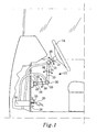
- FIG. 1 shows a steering wheel arrangement 10 for a motor vehicle.
- the steering wheel arrangement comprises a steering column 12 having a first end for cooperation with a steering wheel 14 and a second end for cooperation with a vehicle steering mechanism (not shown).
- the steering wheel arrangement 10 comprises a suspension arrangement for the steering column 12, which suspension arrangement comprises a first supporting arm 16 having a first end and a second end. The first end is pivotally connected to the vehicle via a first pivot joint 18.
- the pivot joint 18 may be fixed to the vehicle by bearings in a bracket solidly joined to the vehicle.
- the bracket may be mounted directly in a pedal plate or a supporting portion of the vehicle cab, e.g. a wind shield beam.
- the suspension arrangement further comprises a second supporting arm 20 having a first end and a second end.
- the first end is pivotally connected to the second end of the first supporting arm 16 via a second pivot joint 22.
- the second end is pivotally connected to the steering column 12 via a third pivot joint 24.
- This third pivot joint 24 permits the angle of the steering wheel 14 to be adjusted, i.e, allows the steering wheel to be tiltable as depicted by arrow 25.
- the first and second supporting arms 16, 20 act as an adjustable suspension arrangement which arrangement makes possible the pattern of movement depicted by the arrows 26 and 28 in Figure 1 .
- the supporting arms 16 and 20 and the steering column 12 can be swung in the same or different directions from an intermediate normal position. E.g. if the movement is counter clockwise, then the steering wheel 14 may be moved upwards and forwards as mentioned above, to thereby provide a large free space for facilitating entry and exit of the vehicle.
- the first, second and third pivot joints 18, 22 and 24 comprise first, second and third locking arrangements 29, 30 and 31, respectively.
- the first locking arrangement 29 locks the first pivot joint 18, i.e. locks the first supporting arm 16 relative to the vehicle.
- the second locking arrangement 30 locks the second pivot joint 22, i.e. locks the second supporting arm 20 relative to the first supporting arm 16.
- the third locking arrangement 31 locks the third pivot joint 24, i.e. locks the steering column 12 relative to the second supporting arm 20.
- the locking arrangements 29, 30 and 31 may be any suitable locking arrangement, e.g. a package of friction plates, as described in American patent no. 5 259 264 .
- a foot pedal 32 is used as depicted in Figure 1 .
- An advantage of using a foot pedal is that the driver can keep both hands on the steering wheel during adjustment.
- the foot pedal 32 in accordance of the present invention is depressible to a first position and then to a second position making it possible to carry out the adjustment in two steps using the same foot pedal as can be seen from Figures 2b and 2c .
- the foot pedal 32 is initially depressible e.g. against a small resistance from a first spring 33, to a first position, see Figure 2b associated with a distinct stop caused by a force increase and depressible to a subsequent second position see Figure 2c by overcoming said force increase such that a driver depressing the foot pedal 32 will feel the distinct stop when the pedal reaches the first position. This prevents the foot pedal 32 from being depressed to the second position by mistake.
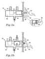
- the force increase may be realized in a suitable way e.g. by a magnetic plunger 38 as shown in Figures 2a, b and c .
- the foot pedal 32 is depressed until it reaches a first end 39 of a rod 40; this corresponds to the first position.
- the rod extends through a magnet 42 and is at its second end mounted to a ferrous element 44.
- the ferrous element 44 is forced against the magnet 42 by magnetic flux and, as shown in Figure 2b , hinders the foot pedal 32 from continuing to the second position by mistake.
- the foot pedal in the first position is further depressed, it displaces the rod 40 so that the magnetic force is overcome and the ferrous plate 44 is released from the magnet 42, to result in the position shown in Figure 2c .
- the foot pedal 32 can thus be depressed to the second position.
- the plate 44 may be substituted by a magnet.
- the "magnet" 42 through which the rod passes will be made of ferrous material.
- the force increase may also be realized in other suitable ways e.g. by a second spring of e.g. rubber or metallic acting on the foot pedal 32 when the foot pedal 32 reaches the first position, i.e. the distinct stop associated with this first position is realized by the force of the second spring.
- the second spring force may remain during the release to the second position.
- the steering wheel arrangement 10 further comprises a release arrangement 34.
- the release arrangement 34 may for example be mechanical as in the form of a release cable 36 as depicted in Figure 3a and 3b , pneumatic in the form of pneumatic switches 50, 52, as depicted in Figures1 , 2a , 2b and 2c , or hydraulic (not shown).
- the foot pedal 32 controls the locking arrangement 29, 30 and 31 of each of the three pivot joints 18, 22 and 24 by means of the release arrangement 34 such that in its first position the foot pedal 32 is arranged to release, via the release arrangement 34, either one or two of the first, second and third locking arrangements 29, 30 and 31 to thereby permit adjustment of the steering wheel arrangement 10 about the pivot joint(s) associated with the respective locking arrangement(s).
- the foot pedal 32 In its second position the foot pedal 32 is arranged to, via the release arrangement 34, lock the locking arrangement(s) released in the first position of said foot pedal 32 and release the remaining locking arrangement(s) to permit further adjustment of the steering wheel arrangement 10.
- each of the first, second and third locking arrangements 29, 30 and 31 in a locked state.
- the suspension arrangement and steering column 12 are thus fixed in a set position.
- the first locking arrangement 29 and the second locking arrangement 30 are released. This causes that the first pivot joint 18 and the second pivot joint 22 become adjustable.
- the third locking arrangement 31 is still locked and the third pivot joint 24 is unable to be adjusted.
- the first and second supporting arms 16 and 20 can be swung (in the pattern of movement shown by arrows 26 and 28 in Figure 1 ) in a suitable direction to set the suspension arrangement in the desired position.
- the foot pedal 32 can be depressed passed the first position direct by to the second position, in which only the third pivot joint 24 and thus the steering column 12 is adjustable. If only the suspension arrangement requires adjustment, the foot pedal 32 is released after the desired adjustment has been made in the first position.
- the release arrangement 34 is pneumatic and is shown in Figures 2a, b and c .
- the pneumatic release arrangement comprises a passage 46 through which air is flushed into a chamber 48. It further comprises a first pneumatic switch 50 connected to and controlling the first locking arrangement 39 and the second locking arrangement 30. When the first switch 50 is open, air flushes from the chamber 48 via the switch 50 and acts on the first locking arrangement 29 and the second locking arrangement 30 such that they release and the first and second pivot joints 18 and 22 become adjustable.
- the first and second supporting arms 16 and 20 can then be swung (in the pattern of movement shown by the arrows 26 and 28 in Figure 1 ) in the suitable direction to set the suspension arrangement to the desired position.
- the pneumatic release arrangement further comprises a second pneumatic switch 52 connected to and controlling the third locking arrangement 31.
- a second pneumatic switch 52 connected to and controlling the third locking arrangement 31.
- air can flush from the chamber 48 via the second switch 52 to act on the third locking arrangement 31 such that it releases and renders the third pivot joint 24 adjustable.
- the second switch 52 is closed, no air can flush from the chamber 48 via the second switch 52.
- the third locking arrangement 31 is then in a locked position and the third pivot joint 24 is no longer adjustable.
- the steering column 12 is thus fixed in its set position.
- Figure 2a depicts the pneumatic release arrangement in a position where the foot pedal 32 is not depressed. In this position, the first pneumatic switch 50 and the second pneumatic switch 52 are closed. The suspension arrangement and the steering column 12 are thus fixed in a set position.
- Figure 2b depicts the pneumatic release arrangement in a position where the foot pedal 32 is depressed to the first position. In this position, the first pneumatic switch 50 is open and the second pneumatic switch 52 is closed. The suspension arrangement is then adjustable while the steering column 12 remains fixed in the set position.
- Figure 2c depicts the pneumatic release arrangement in a position where the foot pedal 32 is depressed to the second position. In this position, the first pneumatic switch 50 is closed and the second pneumatic switch 52 is open. The suspension arrangement is then fixed in its set position and the steering column 12 becomes adjustable.
- the release arrangement 34 may also be hydraulic, being arranged as the pneumatic release arrangement above, but using oil instead of air in the switches.
- the release arrangement 34 may also be mechanical.
- Figure 3a depicts a mechanical release arrangement comprising a release cable 36 being connected to the foot pedal 32 and controls the locking arrangement 29, 30 and 31 of each of the three pivot joints.
- the release cable releases the first locking arrangement 29 and the second locking arrangement 30 in a suitable way, e.g. by disconnecting a slider with a cam in each respective locking arrangement 29, 30 and 31, which cam will release a locking spring or similar.
- the third locking arrangement 31 remains locked.
- a further connection 22 of the release cable to the third locking arrangement 31 will then release the third locking arrangement 31 via another cam. This may be attained by using an eccentric cam.
- the first and second locking arrangements 29 and 30 then become locked.
- Figure 3b depicts an alternative mechanical release arrangement, wherein two release cables 37, 39 may be connected directly by the foot pedal 32 to the locking arrangements 29,30,31 such that when the foot pedal 32 is depressed to the first position a first release cable 37 releases the first and second locking arrangement 29 and 30.
- the third locking arrangement 31 remains locked.
- a second release cable 39 releases the third locking arrangement 31.
- the first and second locking arrangements 29 and 30 become locked. This may also be attained by an eccentric cam arrangement.
- the third pivot joint 24 may be adjustable in a first step and the first and second pivot points 18 and 22 in a second step or the third and the first pivot points 24 and 18 in a first step and the second pivot point 22 in a second step, etc.
Landscapes
- Engineering & Computer Science (AREA)
- Chemical & Material Sciences (AREA)
- Combustion & Propulsion (AREA)
- Transportation (AREA)
- Mechanical Engineering (AREA)
- Mechanical Control Devices (AREA)
- Power Steering Mechanism (AREA)
- Arrangements For Transmission Of Measured Signals (AREA)
- Tires In General (AREA)
- Steering Controls (AREA)
Claims (14)
- Eine Lenkradanordnung (10) für ein Kraftfahrzeug, umfassend
eine Lenksäule (12), die ein erstes Ende zum Zusammenwirken mit einem Lenkrad (14) und ein zweites Ende zum Zusammenwirken mit einem Fahrzeuglenkmechanismus hat; ein drückbares Fußpedal (32);
eine Aufhängevorrichtung für die Lenksäule (12), wobei die Aufhängevorrichtung umfasst:einen ersten Stützarm (16), der ein erstes Ende und ein zweites Ende hat, wobei das erste Ende mittels eines ersten Schwenkgelenkes (18) schwenkbar mit dem Fahrzeug verbunden ist,dadurch gekennzeichnet, dass die Aufhängevorrichtung des weiteren einen zweiten Stützarm (20) umfasst, der ein erstes Ende und ein zweites Ende hat, wobei das erste Ende mittels eines zweiten Schwenkgelenkes (22) schwenkbar mit dem zweiten Ende des ersten Stützarms (16) verbunden ist, und wobei das zweite Ende mittels eines dritten Schwenkgelenkes (24) schwenkbar mit der Lenksäule (12) verbunden ist, wobei die ersten, zweiten und dritten Schwenkgelenke (18, 22, 24) erste, zweite bzw. dritte Verriegelungsmechanismen (29, 30, 31) umfassen,dass das Fußpedal (32), anfangs in eine erste Position, welche einem durch Kraftanstieg verursachten, ausgeprägten Anschlag zugeordnet ist, niederdrückbar ist und durch Überwinden dieses Kraftanstiegs in eine darauffolgende zweite Position niederdrückbar ist, worin das Fußpedal (32) so angelegt ist, dass es in der ersten Position entweder einen oder zwei der ersten, zweiten und dritten Verriegelungsmechanismen (29, 30, 31) freigibt, um dadurch ein Justieren der Lenkradanordnung (10) um die Schwenkgelenke zu gestatten, die den jeweiligen Verriegelungsmechanismen (29, 30, 31) zugeordnet sind, und worin das Fußpedal (32) so angelegt ist, dass es in der zweiten Position die Verriegelungsmechanismen, die in der ersten Position des Fußpedals (32) freigegeben wurden, verriegelt und die übrigen Verriegelungsmechanismen freigibt, um ein weiteres Justieren der Lenkradanordnung (10) zu gestatten. - Lenkradanordnung (10) nach Anspruch 1, worin der Kraftanstieg mittels eines magnetischen Stößels (38) bewirkt wird, der einen Magneten (42) umfasst, welcher durch Magnetkraft auf ein eisernes Element (44) wirkt, worin das Fußpedal (32) niederdrückbar ist, bis es den magnetischen Stößel (38) erreicht, welcher der ersten Position entspricht und das Fußpedal mittels der Magnetkraft daran hindert, sich weiter zur zweiten Position zu bewegen, und worin das Fußpedal (32) weiter bis zum Erreichen der zweiten Position niederdrückbar ist, indem der Kraftanstieg überwunden wird, so dass das eiserne Element (44) vom Magneten (42) gelöst wird.
- Lenkradanordnung (10) nach Anspruch 1, worin der Kraftanstieg mittels einer zweiten Feder bewirkt wird, die auf das Fußpedal (32) wirkt, wenn das Fußpedal (32) die erste Position erreicht.
- Lenkradanordnung (10) nach einem der Ansprüche 1 bis 3, worin das Fußpedal (32) dazu ausgelegt ist, den ersten, zweiten und dritten Verriegelungsmechanismus (29, 30, 31) mittels einer Entriegelungsanordnung (34) freizugegeben.
- Lenkradanordnung nach Anspruch 4, worin die Entriegelungsanordnung (34) pneumatisch ist und einen ersten pneumatischen Schalter (50) umfasst, der mit dem Fußpedal (32) verbunden ist und entweder einen oder zwei der Verriegelungsmechanismen (29, 30, 31) steuert, und einen zweiten pneumatischen Schalter (52) umfasst, der den oder die übrigen Verriegelungsmechanismen steuert.
- Lenkradanordnung nach Anspruch 4, worin die Entriegelungsanordnung mechanisch ist und ein Entriegelungskabel (36) umfasst, das mit dem Fußpedal (32) verbunden ist und die Verriegelungsmechanismen (29, 30, 31) steuert.
- Lenkradanordnung nach Anspruch 4, worin die Entriegelungsanordnung mechanisch ist und ein erstes Entriegelungskabel (37) umfasst, das mit dem Fußpedal (32) verbunden ist und entweder einen oder zwei der Verriegelungsmechanismen (29, 30, 31) steuert, und ein zweites Entriegelungskabel (36) umfasst, das den oder die übrigen Verriegelungsmechanismen steuert.
- Lenkradanordnung nach Anspruch 4, worin die Entriegelungsanordnung hydraulisch ist und einen ersten hydraulischen Schalter umfasst, der mit dem Fußpedal (32) verbunden ist und entweder einen oder zwei der Verriegelungsmechanismen (29, 30, 31) steuert, und einen zweiten hydraulischen Schalter umfasst, der den oder die übrigen Verriegelungsmechanismen steuert.
- Lenkradanordnung nach einem der Ansprüche 1 bis 8, worin das Fußpedal (32) so angelegt ist, dass in der ersten Position der zweite und der dritte Verriegelungsmechanismus (30, 31) freigegeben werden, um dadurch ein Justieren der Lenkradanordnung (10) um die Schwenkgelenke zu gestatten, die den jeweiligen Verriegelungsmechanismen zugeordnet sind, und worin das Fußpedal (32) in der zweiten Position so angelegt ist, dass die Verriegelungsmechanismen (30, 31), die in der ersten Position des Fußpedals (32) freigegeben wurden, verriegelt werden und der erste Verriegelungsmechanismus (29) freigegeben wird, um ein weiteres Justieren der Lenkradanordnung (10) zu gestatten.
- Lenkradanordnung nach einem der Ansprüche 1 bis 8, worin das Fußpedal (32) so angelegt ist, dass in der ersten Position der erste und der zweite Verriegelungsmechanismus (29, 30) freigegeben werden, um dadurch ein Justieren der Lenkradanordnung (10) um die Schwenkgelenke zu gestatten, die den jeweiligen Verriegelungsmechanismen zugeordnet sind, und worin das Fußpedal (32) in der zweiten Position so angelegt ist, dass die Verriegelungsmechanismen (29, 30), die in der ersten Position des Fußpedals (32) freigegeben wurden, verriegelt werden und der dritte Verriegelungsmechanismus (31) freigegeben wird, um ein weiteres Justieren der Lenkradanordnung (10) zu gestatten.
- Lenkradanordnung nach einem der Ansprüche 1 bis 8, worin das Fußpedal (32) so angelegt ist, dass in der ersten Position der erste und der dritte Verriegelungsmechanismus (29, 31) freigegeben werden, um dadurch ein Justieren der Lenkradanordnung (10) um die Schwenkgelenke zu gestatten, die den jeweiligen Verriegelungsmechanismen zugeordnet sind, und worin das Fußpedal (32) in der zweiten Position so angelegt ist, dass die Verriegelungsmechanismen (29, 31 die in der ersten Position des Fußpedals (32) freigegeben wurden, verriegelt werden und der zweite Verriegelungsmechanismus (30) freigegeben wird, um ein weiteres Justieren der Lenkradanordnung (10) zu gestatten.
- Lenkradanordnung nach einem der Ansprüche 1 bis 8, worin das Fußpedal (32) so angelegt ist, dass in der ersten Position der erste Verriegelungsmechanismus (29) freigegeben wird, um dadurch ein Justieren der Lenkradanordnung (10) um das Schwenkgelenk zu gestatten, das dem entsprechenden Verriegelungsmechanismus zugeordnet ist, und worin das Fußpedal (32) in der zweiten Position so angelegt ist, dass der Verriegelungsmechanismus (29), der in der ersten Position des Fußpedals (32) freigegeben wurde, verriegelt wird und der zweite und dritte Verriegelungsmechanismus (30, 31) freigegeben werden, um ein weiteres Justieren der Lenkradanordnung (10) zu gestatten.
- Lenkradanordnung nach einem der Ansprüche 1 bis 8, worin das Fußpedal (32) so angelegt ist, dass in der ersten Position der zweite Verriegelungsmechanismus (30) freigegeben wird, um dadurch das Justieren der Lenkradanordnung (10) um das Schwenkgelenk zu gestatten, das dem entsprechenden Verriegelungsmechanismus zugeordnet ist, und worin das Fußpedal (32) in der zweiten Position so angelegt ist, dass der Verriegelungsmechanismus (30), der in der ersten Position des Fußpedals (32) freigegeben wurde, verriegelt wird und der erste und dritte Verriegelungsmechanismus (29, 31) freigegeben werden, um ein weiteres Justieren der Lenkradanordnung (10) zu gestatten.
- Lenkradanordnung nach einem der Ansprüche 1 bis 8, worin das Fußpedal (32) so angelegt ist, dass in der ersten Position der dritte Verriegelungsmechanismus (31) freigegeben wird, um dadurch ein Justieren der Lenkradanordnung (10) um das Schwenkgelenk zu gestatten, das dem entsprechenden Verriegelungsmechanismus zugeordnet ist, und worin das Fußpedal (32) in der zweiten Position so angelegt ist, dass der Verriegelungsmechanismus (31), der in der ersten Position des Fußpedals (32) freigegeben wurde, verriegelt wird und der erste und zweite Verriegelungsmechanismus (29, 30) freigegeben werden, um ein weiteres Justieren der Lenkradanordnung (10) zu gestatten.
Applications Claiming Priority (1)
| Application Number | Priority Date | Filing Date | Title |
|---|---|---|---|
| PCT/SE2005/001628 WO2007050004A1 (en) | 2005-10-28 | 2005-10-28 | STEERlNG WHEEL ARRANGEMENT |
Publications (3)
| Publication Number | Publication Date |
|---|---|
| EP1940669A1 EP1940669A1 (de) | 2008-07-09 |
| EP1940669A4 EP1940669A4 (de) | 2011-01-12 |
| EP1940669B1 true EP1940669B1 (de) | 2012-01-11 |
Family
ID=37968042
Family Applications (1)
| Application Number | Title | Priority Date | Filing Date |
|---|---|---|---|
| EP05797033A Expired - Lifetime EP1940669B1 (de) | 2005-10-28 | 2005-10-28 | Lenkradanordnung |
Country Status (5)
| Country | Link |
|---|---|
| US (1) | US8117940B2 (de) |
| EP (1) | EP1940669B1 (de) |
| CN (1) | CN101296835B (de) |
| AT (1) | ATE540849T1 (de) |
| WO (1) | WO2007050004A1 (de) |
Families Citing this family (8)
| Publication number | Priority date | Publication date | Assignee | Title |
|---|---|---|---|---|
| DE102007028770B4 (de) * | 2007-06-22 | 2019-08-14 | Dr. Ing. H.C. F. Porsche Aktiengesellschaft | Lenksäulenanordnung für ein Kraftfahrzeug |
| US10207697B2 (en) * | 2015-12-21 | 2019-02-19 | Ford Global Technologies, Llc | Movable steering wheel for autonomous vehicle |
| US20160304113A1 (en) * | 2016-06-27 | 2016-10-20 | Caterpillar Inc. | Steering column for machine |
| BR102018015638B1 (pt) * | 2018-07-31 | 2022-11-08 | Cnh Industrial Brasil Ltda | Suporte para volante de um veículo e veículo de uso rural ou na construção civil |
| CN110406587B (zh) * | 2019-09-04 | 2024-10-25 | 三一重机有限公司 | 一种方向柱倾角调节机构及方向机 |
| KR20230153551A (ko) * | 2022-04-28 | 2023-11-07 | 현대자동차주식회사 | 폴더블 스티어링휠 |
| US20240199143A1 (en) | 2022-12-14 | 2024-06-20 | Cnh Industrial America Llc | Cab system for a vehicle |
| CN119329745B (zh) * | 2024-10-15 | 2026-03-20 | 中国直升机设计研究所 | 一种直升机减振脚蹬 |
Family Cites Families (10)
| Publication number | Priority date | Publication date | Assignee | Title |
|---|---|---|---|---|
| SE465563B (sv) * | 1989-10-31 | 1991-09-30 | Volvo Ab | Justerbar fordonsratt |
| US5126731A (en) * | 1990-06-15 | 1992-06-30 | Cromer Jr Jerry E | Pneumatically-controlled, user-operated switch interface |
| US5168768A (en) * | 1992-01-14 | 1992-12-08 | Deere & Company | Tilt steering column assembly |
| DE4235588A1 (de) | 1992-10-22 | 1994-04-28 | Stabilus Gmbh | Hydropneumatisches Verstellelement |
| DE19522389C1 (de) * | 1995-06-23 | 1996-09-19 | Daimler Benz Ag | Sicherheitslenksäule |
| EP0841236B1 (de) | 1996-11-12 | 2002-08-28 | New Holland Belgium N.V. | Vierfach verstellbare, sockelbodenbefestigte Lenksäule für einen Mähdrescher |
| US5890397A (en) * | 1997-02-24 | 1999-04-06 | New Holland North America, Inc. | Four-way adjustable pedestal floor mounted steering column for a combine harvester |
| US6213912B1 (en) * | 1999-11-10 | 2001-04-10 | Deere & Company | Low speed return |
| WO2003022616A1 (de) * | 2001-08-31 | 2003-03-20 | Siemens Aktiengesellschaft | Verschleissfreier fahrpedal-kick-down-schalter |
| CN1620383A (zh) * | 2003-03-05 | 2005-05-25 | Iii.埃拉迪奥 于莱加恩N. | 转向管柱联轴节以下的转向转动圆柱上的锁定柄 |
-
2005
- 2005-10-28 EP EP05797033A patent/EP1940669B1/de not_active Expired - Lifetime
- 2005-10-28 CN CN2005800519582A patent/CN101296835B/zh not_active Expired - Fee Related
- 2005-10-28 US US12/091,755 patent/US8117940B2/en active Active
- 2005-10-28 WO PCT/SE2005/001628 patent/WO2007050004A1/en not_active Ceased
- 2005-10-28 AT AT05797033T patent/ATE540849T1/de active
Also Published As
| Publication number | Publication date |
|---|---|
| US20090173180A1 (en) | 2009-07-09 |
| CN101296835A (zh) | 2008-10-29 |
| EP1940669A4 (de) | 2011-01-12 |
| CN101296835B (zh) | 2010-06-16 |
| ATE540849T1 (de) | 2012-01-15 |
| US8117940B2 (en) | 2012-02-21 |
| WO2007050004A1 (en) | 2007-05-03 |
| EP1940669A1 (de) | 2008-07-09 |
Similar Documents
| Publication | Publication Date | Title |
|---|---|---|
| US20090266195A1 (en) | Adjustable steering column assembly | |
| US5259264A (en) | Adjustable steering wheel | |
| EP0928727A3 (de) | Fahrzeugbremspedalanordnung | |
| US20040079613A1 (en) | Shift lock device for a shift lever in an automatic transmission | |
| US8117940B2 (en) | Steering wheel arrangement | |
| US20070266816A1 (en) | Adjustable pedal device | |
| NO327467B1 (no) | Anordning for bruk av ekstra styreanordning i et kjoretoy | |
| JPH05262238A (ja) | チルト・テレスコピックステアリング装置 | |
| US5467663A (en) | Control cable for a vehicle system | |
| US20100326759A1 (en) | Hand control apparatus in a vehicle | |
| JP2005231547A (ja) | 自動車の操作ペダル装置 | |
| JPH05288266A (ja) | 車両のパーキングロック解除装置 | |
| US6000511A (en) | Arrangement of foot operating elements for a motor vehicle | |
| US7326148B2 (en) | Control system for electronic actuated shifter | |
| US20260104728A1 (en) | Pedal assembly for a vehicle | |
| WO2016121154A1 (ja) | 車両用ペダル装置の後退防止装置 | |
| US6390226B1 (en) | Differential lock engaging arrangement | |
| KR100511857B1 (ko) | 자동차의 브레이크 페달 시스템 | |
| JP3693800B2 (ja) | コラムシフト装置 | |
| CA1238625A (en) | Adjustable control console | |
| DE102013221783A1 (de) | Brems- oder Kupplungshebel an einer Lenkstange eines Kraftrades | |
| US7040191B2 (en) | Device for adjusting a rotationally mounted connecting piece | |
| JPH0719334A (ja) | 車両用自動変速機のシフトロック装置 | |
| WO2017006628A1 (ja) | 車両用ペダル装置の後退防止装置 | |
| JP2019032723A (ja) | 車両用操作ペダル装置 |
Legal Events
| Date | Code | Title | Description |
|---|---|---|---|
| PUAI | Public reference made under article 153(3) epc to a published international application that has entered the european phase |
Free format text: ORIGINAL CODE: 0009012 |
|
| 17P | Request for examination filed |
Effective date: 20080326 |
|
| AK | Designated contracting states |
Kind code of ref document: A1 Designated state(s): AT BE BG CH CY CZ DE DK EE ES FI FR GB GR HU IE IS IT LI LT LU LV MC NL PL PT RO SE SI SK TR |
|
| A4 | Supplementary search report drawn up and despatched |
Effective date: 20101215 |
|
| RIC1 | Information provided on ipc code assigned before grant |
Ipc: B62D 1/184 20060101AFI20110531BHEP Ipc: B62D 1/189 20060101ALI20110531BHEP |
|
| GRAP | Despatch of communication of intention to grant a patent |
Free format text: ORIGINAL CODE: EPIDOSNIGR1 |
|
| GRAS | Grant fee paid |
Free format text: ORIGINAL CODE: EPIDOSNIGR3 |
|
| GRAA | (expected) grant |
Free format text: ORIGINAL CODE: 0009210 |
|
| AK | Designated contracting states |
Kind code of ref document: B1 Designated state(s): AT BE BG CH CY CZ DE DK EE ES FI FR GB GR HU IE IS IT LI LT LU LV MC NL PL PT RO SE SI SK TR |
|
| DAX | Request for extension of the european patent (deleted) | ||
| REG | Reference to a national code |
Ref country code: GB Ref legal event code: FG4D |
|
| REG | Reference to a national code |
Ref country code: CH Ref legal event code: EP |
|
| REG | Reference to a national code |
Ref country code: AT Ref legal event code: REF Ref document number: 540849 Country of ref document: AT Kind code of ref document: T Effective date: 20120115 |
|
| REG | Reference to a national code |
Ref country code: IE Ref legal event code: FG4D |
|
| REG | Reference to a national code |
Ref country code: DE Ref legal event code: R096 Ref document number: 602005032170 Country of ref document: DE Effective date: 20120308 |
|
| REG | Reference to a national code |
Ref country code: SE Ref legal event code: TRGR |
|
| REG | Reference to a national code |
Ref country code: NL Ref legal event code: VDEP Effective date: 20120111 |
|
| PG25 | Lapsed in a contracting state [announced via postgrant information from national office to epo] |
Ref country code: SI Free format text: LAPSE BECAUSE OF FAILURE TO SUBMIT A TRANSLATION OF THE DESCRIPTION OR TO PAY THE FEE WITHIN THE PRESCRIBED TIME-LIMIT Effective date: 20120111 |
|
| LTIE | Lt: invalidation of european patent or patent extension |
Effective date: 20120111 |
|
| PG25 | Lapsed in a contracting state [announced via postgrant information from national office to epo] |
Ref country code: LT Free format text: LAPSE BECAUSE OF FAILURE TO SUBMIT A TRANSLATION OF THE DESCRIPTION OR TO PAY THE FEE WITHIN THE PRESCRIBED TIME-LIMIT Effective date: 20120111 Ref country code: BE Free format text: LAPSE BECAUSE OF FAILURE TO SUBMIT A TRANSLATION OF THE DESCRIPTION OR TO PAY THE FEE WITHIN THE PRESCRIBED TIME-LIMIT Effective date: 20120111 Ref country code: BG Free format text: LAPSE BECAUSE OF FAILURE TO SUBMIT A TRANSLATION OF THE DESCRIPTION OR TO PAY THE FEE WITHIN THE PRESCRIBED TIME-LIMIT Effective date: 20120411 Ref country code: IS Free format text: LAPSE BECAUSE OF FAILURE TO SUBMIT A TRANSLATION OF THE DESCRIPTION OR TO PAY THE FEE WITHIN THE PRESCRIBED TIME-LIMIT Effective date: 20120511 Ref country code: NL Free format text: LAPSE BECAUSE OF FAILURE TO SUBMIT A TRANSLATION OF THE DESCRIPTION OR TO PAY THE FEE WITHIN THE PRESCRIBED TIME-LIMIT Effective date: 20120111 |
|
| PG25 | Lapsed in a contracting state [announced via postgrant information from national office to epo] |
Ref country code: PL Free format text: LAPSE BECAUSE OF FAILURE TO SUBMIT A TRANSLATION OF THE DESCRIPTION OR TO PAY THE FEE WITHIN THE PRESCRIBED TIME-LIMIT Effective date: 20120111 Ref country code: GR Free format text: LAPSE BECAUSE OF FAILURE TO SUBMIT A TRANSLATION OF THE DESCRIPTION OR TO PAY THE FEE WITHIN THE PRESCRIBED TIME-LIMIT Effective date: 20120412 Ref country code: LV Free format text: LAPSE BECAUSE OF FAILURE TO SUBMIT A TRANSLATION OF THE DESCRIPTION OR TO PAY THE FEE WITHIN THE PRESCRIBED TIME-LIMIT Effective date: 20120111 Ref country code: FI Free format text: LAPSE BECAUSE OF FAILURE TO SUBMIT A TRANSLATION OF THE DESCRIPTION OR TO PAY THE FEE WITHIN THE PRESCRIBED TIME-LIMIT Effective date: 20120111 Ref country code: PT Free format text: LAPSE BECAUSE OF FAILURE TO SUBMIT A TRANSLATION OF THE DESCRIPTION OR TO PAY THE FEE WITHIN THE PRESCRIBED TIME-LIMIT Effective date: 20120511 |
|
| REG | Reference to a national code |
Ref country code: AT Ref legal event code: MK05 Ref document number: 540849 Country of ref document: AT Kind code of ref document: T Effective date: 20120111 |
|
| PG25 | Lapsed in a contracting state [announced via postgrant information from national office to epo] |
Ref country code: CY Free format text: LAPSE BECAUSE OF FAILURE TO SUBMIT A TRANSLATION OF THE DESCRIPTION OR TO PAY THE FEE WITHIN THE PRESCRIBED TIME-LIMIT Effective date: 20120111 |
|
| PG25 | Lapsed in a contracting state [announced via postgrant information from national office to epo] |
Ref country code: RO Free format text: LAPSE BECAUSE OF FAILURE TO SUBMIT A TRANSLATION OF THE DESCRIPTION OR TO PAY THE FEE WITHIN THE PRESCRIBED TIME-LIMIT Effective date: 20120111 Ref country code: DK Free format text: LAPSE BECAUSE OF FAILURE TO SUBMIT A TRANSLATION OF THE DESCRIPTION OR TO PAY THE FEE WITHIN THE PRESCRIBED TIME-LIMIT Effective date: 20120111 Ref country code: CZ Free format text: LAPSE BECAUSE OF FAILURE TO SUBMIT A TRANSLATION OF THE DESCRIPTION OR TO PAY THE FEE WITHIN THE PRESCRIBED TIME-LIMIT Effective date: 20120111 Ref country code: EE Free format text: LAPSE BECAUSE OF FAILURE TO SUBMIT A TRANSLATION OF THE DESCRIPTION OR TO PAY THE FEE WITHIN THE PRESCRIBED TIME-LIMIT Effective date: 20120111 |
|
| PLBE | No opposition filed within time limit |
Free format text: ORIGINAL CODE: 0009261 |
|
| STAA | Information on the status of an ep patent application or granted ep patent |
Free format text: STATUS: NO OPPOSITION FILED WITHIN TIME LIMIT |
|
| PG25 | Lapsed in a contracting state [announced via postgrant information from national office to epo] |
Ref country code: SK Free format text: LAPSE BECAUSE OF FAILURE TO SUBMIT A TRANSLATION OF THE DESCRIPTION OR TO PAY THE FEE WITHIN THE PRESCRIBED TIME-LIMIT Effective date: 20120111 Ref country code: IT Free format text: LAPSE BECAUSE OF FAILURE TO SUBMIT A TRANSLATION OF THE DESCRIPTION OR TO PAY THE FEE WITHIN THE PRESCRIBED TIME-LIMIT Effective date: 20120111 |
|
| 26N | No opposition filed |
Effective date: 20121012 |
|
| PG25 | Lapsed in a contracting state [announced via postgrant information from national office to epo] |
Ref country code: AT Free format text: LAPSE BECAUSE OF FAILURE TO SUBMIT A TRANSLATION OF THE DESCRIPTION OR TO PAY THE FEE WITHIN THE PRESCRIBED TIME-LIMIT Effective date: 20120111 |
|
| REG | Reference to a national code |
Ref country code: DE Ref legal event code: R097 Ref document number: 602005032170 Country of ref document: DE Effective date: 20121012 |
|
| PG25 | Lapsed in a contracting state [announced via postgrant information from national office to epo] |
Ref country code: ES Free format text: LAPSE BECAUSE OF FAILURE TO SUBMIT A TRANSLATION OF THE DESCRIPTION OR TO PAY THE FEE WITHIN THE PRESCRIBED TIME-LIMIT Effective date: 20120422 |
|
| PG25 | Lapsed in a contracting state [announced via postgrant information from national office to epo] |
Ref country code: MC Free format text: LAPSE BECAUSE OF NON-PAYMENT OF DUE FEES Effective date: 20121031 |
|
| REG | Reference to a national code |
Ref country code: CH Ref legal event code: PL |
|
| PG25 | Lapsed in a contracting state [announced via postgrant information from national office to epo] |
Ref country code: LI Free format text: LAPSE BECAUSE OF NON-PAYMENT OF DUE FEES Effective date: 20121031 Ref country code: CH Free format text: LAPSE BECAUSE OF NON-PAYMENT OF DUE FEES Effective date: 20121031 |
|
| REG | Reference to a national code |
Ref country code: IE Ref legal event code: MM4A |
|
| PG25 | Lapsed in a contracting state [announced via postgrant information from national office to epo] |
Ref country code: IE Free format text: LAPSE BECAUSE OF NON-PAYMENT OF DUE FEES Effective date: 20121028 |
|
| PG25 | Lapsed in a contracting state [announced via postgrant information from national office to epo] |
Ref country code: TR Free format text: LAPSE BECAUSE OF FAILURE TO SUBMIT A TRANSLATION OF THE DESCRIPTION OR TO PAY THE FEE WITHIN THE PRESCRIBED TIME-LIMIT Effective date: 20120111 |
|
| PG25 | Lapsed in a contracting state [announced via postgrant information from national office to epo] |
Ref country code: LU Free format text: LAPSE BECAUSE OF NON-PAYMENT OF DUE FEES Effective date: 20121028 |
|
| PG25 | Lapsed in a contracting state [announced via postgrant information from national office to epo] |
Ref country code: HU Free format text: LAPSE BECAUSE OF FAILURE TO SUBMIT A TRANSLATION OF THE DESCRIPTION OR TO PAY THE FEE WITHIN THE PRESCRIBED TIME-LIMIT Effective date: 20051028 |
|
| REG | Reference to a national code |
Ref country code: FR Ref legal event code: PLFP Year of fee payment: 11 |
|
| REG | Reference to a national code |
Ref country code: FR Ref legal event code: PLFP Year of fee payment: 12 |
|
| REG | Reference to a national code |
Ref country code: FR Ref legal event code: PLFP Year of fee payment: 13 |
|
| REG | Reference to a national code |
Ref country code: FR Ref legal event code: PLFP Year of fee payment: 14 |
|
| PGFP | Annual fee paid to national office [announced via postgrant information from national office to epo] |
Ref country code: GB Payment date: 20231013 Year of fee payment: 19 |
|
| PGFP | Annual fee paid to national office [announced via postgrant information from national office to epo] |
Ref country code: SE Payment date: 20231017 Year of fee payment: 19 |
|
| PGFP | Annual fee paid to national office [announced via postgrant information from national office to epo] |
Ref country code: DE Payment date: 20241015 Year of fee payment: 20 |
|
| PGFP | Annual fee paid to national office [announced via postgrant information from national office to epo] |
Ref country code: FR Payment date: 20241025 Year of fee payment: 20 |
|
| REG | Reference to a national code |
Ref country code: SE Ref legal event code: EUG |
|
| GBPC | Gb: european patent ceased through non-payment of renewal fee |
Effective date: 20241028 |
|
| PG25 | Lapsed in a contracting state [announced via postgrant information from national office to epo] |
Ref country code: GB Free format text: LAPSE BECAUSE OF NON-PAYMENT OF DUE FEES Effective date: 20241028 |
|
| PG25 | Lapsed in a contracting state [announced via postgrant information from national office to epo] |
Ref country code: SE Free format text: LAPSE BECAUSE OF NON-PAYMENT OF DUE FEES Effective date: 20241029 |
|
| REG | Reference to a national code |
Ref country code: DE Ref legal event code: R071 Ref document number: 602005032170 Country of ref document: DE |