EP1941190B1 - Ventil mit auslasskanal - Google Patents
Ventil mit auslasskanal Download PDFInfo
- Publication number
- EP1941190B1 EP1941190B1 EP06830971A EP06830971A EP1941190B1 EP 1941190 B1 EP1941190 B1 EP 1941190B1 EP 06830971 A EP06830971 A EP 06830971A EP 06830971 A EP06830971 A EP 06830971A EP 1941190 B1 EP1941190 B1 EP 1941190B1
- Authority
- EP
- European Patent Office
- Prior art keywords
- seat
- valve
- valve disk
- duct
- end wall
- Prior art date
- Legal status (The legal status is an assumption and is not a legal conclusion. Google has not performed a legal analysis and makes no representation as to the accuracy of the status listed.)
- Not-in-force
Links
Images
Classifications
-
- F—MECHANICAL ENGINEERING; LIGHTING; HEATING; WEAPONS; BLASTING
- F16—ENGINEERING ELEMENTS AND UNITS; GENERAL MEASURES FOR PRODUCING AND MAINTAINING EFFECTIVE FUNCTIONING OF MACHINES OR INSTALLATIONS; THERMAL INSULATION IN GENERAL
- F16K—VALVES; TAPS; COCKS; ACTUATING-FLOATS; DEVICES FOR VENTING OR AERATING
- F16K1/00—Lift valves or globe valves, i.e. cut-off apparatus with closure members having at least a component of their opening and closing motion perpendicular to the closing faces
- F16K1/32—Details
- F16K1/34—Cutting-off parts, e.g. valve members, seats
- F16K1/36—Valve members
-
- F—MECHANICAL ENGINEERING; LIGHTING; HEATING; WEAPONS; BLASTING
- F16—ENGINEERING ELEMENTS AND UNITS; GENERAL MEASURES FOR PRODUCING AND MAINTAINING EFFECTIVE FUNCTIONING OF MACHINES OR INSTALLATIONS; THERMAL INSULATION IN GENERAL
- F16K—VALVES; TAPS; COCKS; ACTUATING-FLOATS; DEVICES FOR VENTING OR AERATING
- F16K1/00—Lift valves or globe valves, i.e. cut-off apparatus with closure members having at least a component of their opening and closing motion perpendicular to the closing faces
- F16K1/32—Details
- F16K1/34—Cutting-off parts, e.g. valve members, seats
- F16K1/36—Valve members
- F16K1/38—Valve members of conical shape
-
- F—MECHANICAL ENGINEERING; LIGHTING; HEATING; WEAPONS; BLASTING
- F02—COMBUSTION ENGINES; HOT-GAS OR COMBUSTION-PRODUCT ENGINE PLANTS
- F02M—SUPPLYING COMBUSTION ENGINES IN GENERAL WITH COMBUSTIBLE MIXTURES OR CONSTITUENTS THEREOF
- F02M26/00—Engine-pertinent apparatus for adding exhaust gases to combustion-air, main fuel or fuel-air mixture, e.g. by exhaust gas recirculation [EGR] systems
- F02M26/65—Constructional details of EGR valves
- F02M26/66—Lift valves, e.g. poppet valves
- F02M26/68—Closing members; Valve seats; Flow passages
-
- F—MECHANICAL ENGINEERING; LIGHTING; HEATING; WEAPONS; BLASTING
- F16—ENGINEERING ELEMENTS AND UNITS; GENERAL MEASURES FOR PRODUCING AND MAINTAINING EFFECTIVE FUNCTIONING OF MACHINES OR INSTALLATIONS; THERMAL INSULATION IN GENERAL
- F16K—VALVES; TAPS; COCKS; ACTUATING-FLOATS; DEVICES FOR VENTING OR AERATING
- F16K27/00—Construction of housing; Use of materials therefor
- F16K27/02—Construction of housing; Use of materials therefor of lift valves
-
- F—MECHANICAL ENGINEERING; LIGHTING; HEATING; WEAPONS; BLASTING
- F16—ENGINEERING ELEMENTS AND UNITS; GENERAL MEASURES FOR PRODUCING AND MAINTAINING EFFECTIVE FUNCTIONING OF MACHINES OR INSTALLATIONS; THERMAL INSULATION IN GENERAL
- F16K—VALVES; TAPS; COCKS; ACTUATING-FLOATS; DEVICES FOR VENTING OR AERATING
- F16K27/00—Construction of housing; Use of materials therefor
- F16K27/02—Construction of housing; Use of materials therefor of lift valves
- F16K27/0254—Construction of housing; Use of materials therefor of lift valves with conical shaped valve members
Definitions
- the present invention relates to a flow control valve that can be used, for example, in an exhaust gas recirculation circuit (or EGR circuit of the English Exhaust Gas Recirculation) of a motor vehicle engine (car, truck, public transport). , utility ..).
- a flow control valve has been described for example in the document US 2002/0033462 .
- An EGR valve includes a first conduit, ensuring the admission of exhaust gases into the valve, and a second conduit, ensuring the exit of gases from the valve.
- the first conduit is perpendicular to the second conduit and opens into a connecting portion of the second conduit to the first conduit by defining an intersection forming a seat of a sliding valve in the connecting portion of the second conduit in a direction perpendicular to the seat between a position closure in which the valve is applied against the seat and an extreme open position in which the valve is spaced from the seat.
- the valve is moved by means of an actuator between its closed position and its open position to adjust the spacing (or lift) of the valve relative to its seat and thus the section of passage of the exhaust gas , the extreme opening position ensuring a maximum flow of exhaust gas in the valve.
- Anti-pollution standards now make it necessary to recycle a larger share of exhaust gases. It has therefore been envisaged to increase the flow of the exhaust gases in the valves by increasing the lifting of the valve and / or the diameters of the valve and its seat.
- these solutions pose problems of mechanical strength and lead to an increase in the size of the valve, particularly incompatible with, on the one hand, the available space which is increasingly restricted under the bonnet of vehicles and, d 'other on the other hand, the general reduction of vehicles that manufacturers want to limit the fuel consumption of their vehicles.
- An object of the invention is to provide a valve allowing a high flow while having a relatively compact structure.
- a valve comprising a first conduit and a second conduit extending perpendicular to the first conduit, the first conduit opening into a connecting portion of the second conduit defining an intersection forming a seat of a sliding valve in the connecting portion in a direction perpendicular to the seat between a closed position and an open position, the connecting portion having two flat walls opposite and connected by a bottom wall, the first conduit opening on one of the walls; planes and the bottom wall partially surrounding the valve parallel to the direction of sliding at a distance from an edge of the valve such that, for the open position, the bottom wall defines with the edge of the valve and the seat a passage de section ascending from a median axis of the bottom wall to connection areas of the bottom wall to the second conduit.
- the bottom wall is arranged such that, for any angular sector defined between the median axis of the bottom wall and any point of the bottom wall, the passage section defined locally between the bottom wall, the edge of the valve and the seat in the vicinity of this point is at least equal to the product of a coefficient and an effective cross section defined locally above the seat between the edge of the valve and the seat in the angular sector considered.
- This arrangement allows a better circulation of the exhaust gases around the valve and prevents the formation of a clogging at the central portion of the bottom wall.
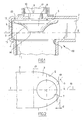
- the valve generally designated 100 comprises a first duct 1 intended to be connected to a gas supply duct and a second duct 2 which extends perpendicularly to the duct 1 and is intended to be connected to a duct exhaust gas.
- the duct 2 has a connecting portion 3 to the duct 1.
- the connecting portion 3 comprises two flat walls 4, 5 facing one another and connected by a bottom wall 6.
- the duct 1 opens into the portion link 3 by the plane wall 4 defining an intersection forming a seat 7 of a valve 8.
- the valve 8 is integral with an actuating rod 9 slidably received in a bore 10 formed in the flat wall 5.
- L Bore 10 extends opposite the seat 7 perpendicular thereto and opens into the connecting portion 3.
- the actuating rod 9 is connected to an actuator 12 fixed to the outside of the duct 2.
- the valve 8 has opposite the seat 7 a deflection surface 13 formed of a generator revolution surface curved here in an arc.
- the deflection surface 13 thus has a curvilinear profile having a narrow base 14 directed towards the seat 7 and flaring away from the seat 7 to a peripheral edge 15 of the valve 8.
- the Generator is tangent to a plane perpendicular to the direction of sliding to merge with this plane.
- the base 14 is formed by the flat end of the actuating rod 9 opposite the actuator 12 which passes through the valve 8 and is welded thereto at the level of the base 14.
- the valve 8 has the opposite of the seat 7 a flat rear surface 16 projecting from the center of which extends a boss 11.
- the bottom wall 6 of the connecting portion 3 surrounds partially the valve 8 parallel to the sliding direction of the valve 8 and joins the rest of the conduit 2 in a connection zone 17.
- the bottom wall 6 is spaced from the peripheral edge 15 by a distance whose determination is explained in connection with the operation of the valve in the following description.
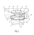
- the actuator 12 thus controls the sliding of the valve 8 in a direction perpendicular to the seat 7 between an extreme closed position in which the valve 8 is applied against the seat 7 and an open position (shown in FIG. figure 1 ), or maximum lift position of the valve 8, wherein the valve 8 is spaced from the seat 7 and the peripheral edge 15 defines with the seat 7 in line with it a theoretical maximum section of gas passage (shown in FIG. mixed line end on the figure 3 and referenced 22).
- the actuator 12 is controlled so that the valve 8 extends in the immediate vicinity of the wall 5. This makes it possible to prevent gases from flowing behind the valve 8 and to cause disruptive turbulence. the flow of gases upstream of the valve. More specifically, in the extreme open position, the boss 11 of the valve 8 is in abutment against the wall 5 so that a space 23 of small thickness is left between the wall 5 and the valve 8. As the boss 11 is resting against the wall 5, the valve 8 closes the bore 10 and prevents particles and dirt carried by the gases are introduced into the bore 10 and alter the quality of the sliding rod 9. space 13 left between the valve 8 and the wall 5 avoids a suction effect opposing the return of the valve 8 from its extreme open position to its extreme closed position.
- the deflection surface 13 has the function of returning perpendicularly to the conduit 1 a gas stream from it.
- the guiding of the gas flow by the deflection surface makes it possible to limit the occurrence of turbulence in the gas flow during the passage thereof from the first duct to the second duct and improves the flow rate in the valve.
- the shape of the deflection surface 13 in the revolution surface of the curved generator facilitates the realization of the valve.
- the shape of the generator in an arc of circle combines simplicity of realization and efficiency.
- the bottom wall 6 of the connecting portion 3 is spaced from the peripheral edge 15 a distance such that, for the extreme open position, the bottom wall 6 defines with the peripheral edge 15 of the valve 8 and the seat 7 a passage 18 of section increasing from a median axis 19 of the bottom wall 6 towards the connection zone 17. More specifically, the bottom wall 6 is arranged in such a way that, for any angular sector ⁇ defined between the central axis 19 and any point of the bottom wall 6, the passage section 20 defined locally between the bottom wall 6, the peripheral edge 15 and the seat 7 in the vicinity of this point is at least equal to an effective cross section 21 defined locally above the seat 7 between the peripheral edge 15 and the seat 7 in the angular sector considered.
- the passage cross section 21 is equal to about half of the theoretical maximum crossing section 22 defined locally in the angular sector considered.
- the passage section 20 is at least equal to the passage cross section 21 assigned a coefficient k greater than 1 and dependent on the angular sector ⁇ considered.
- the coefficient k is equal to ⁇ divided by the angle ⁇ in radian ( ⁇ / ⁇ ).
- the section 20 is equal to four times the section 21.
- the bottom wall 6 is rectilinear and spaced from the valve 8 by a distance d level of the median axis 19 so that the section 20 is greater than the section 21 even for the low values of ⁇ .
- the coefficient dependent on ⁇ makes it possible to take into account the local flow rate of the exhaust gas, which increases as ⁇ increases.
- the stop means of the valve in the open position may be formed of a boss projecting from the flat wall 5.
- the section 20 may be equal to k times the section 21 with 1 ⁇ k ⁇ ⁇ / ⁇ for ⁇ varying between 0 and 2 ⁇ / 3 approximately on either side of the media axis 19.
- the combination of the shape of the second conduit valve deflection surface is its positioning in the open position provide an optimal solution to maximize the flow in the valve.
- Each of these features may, however, be used independently of the others to achieve the invention and only a combination of both of these features is usable.
Landscapes
- Engineering & Computer Science (AREA)
- General Engineering & Computer Science (AREA)
- Mechanical Engineering (AREA)
- Chemical & Material Sciences (AREA)
- Combustion & Propulsion (AREA)
- Lift Valve (AREA)
- Feeding And Controlling Fuel (AREA)
- Percussion Or Vibration Massage (AREA)
- Exhaust-Gas Circulating Devices (AREA)
- Chimneys And Flues (AREA)
- Sampling And Sample Adjustment (AREA)
- Sliding Valves (AREA)
- Joints Allowing Movement (AREA)
Claims (12)
- Ventil (100) mit einem ersten Kanal (1) und mit einem zweiten Kanal (2), der sich lotrecht zum ersten Kanal erstreckt, wobei der ersten Kanal in einem Verbindungsabschnitt (3) des zweiten Kanals mündet, indem er eine Schnittlinie definiert, die einen Sitz (7) einer Ventilklappe (8) bildet, welche im Verbindungsabschnitt in einer Richtung lotrecht zum Sitz zwischen einer Schließstellung und einer Öffnungsstellung gleitet, wobei der Verbindungsabschnitt zwei ebene Wände (4, 5) aufweist, die einander gegenüberliegen und durch eine Rückwand (6) verbunden sind, wobei der erste Kanal auf einer der ebenen Wände (4) mündet, und die Rückwand die Ventilklappe parallel zur Gleitrichtung in einem Abstand zu einem Rand (15) der Ventilklappe teilweise umgibt, dadurch gekennzeichnet, dass für die Öffnungsstellung die Rückwand mit dem Rand der Ventilklappe und dem Sitz einen Durchlass (18) definiert, dessen Querschnitt von einer Mittelachse (19) der Rückwand zu Anschlusszonen (17) der Rückwand an den zweiten Kanal zunimmt.
- Ventil nach Anspruch 1, bei dem die Rückwand (6) so eingerichtet ist, dass für jeden Winkelsektor (θ), der zwischen der Mittelachse (19) der Rückwand und einem beliebigen Punkt der Rückwand definiert wird, der lokal zwischen der Rückwand, dem Rand (15) der Ventilklappe (8) und dem Sitz (7) in der Nähe dieses Punkts definierte Durchlassquerschnitt (18) mindestens gleich dem Produkt aus einem Koeffizienten (k) und aus einem wirksamen Durchlassquerschnitt (21) ist, der lokal lotrecht zum Sitz zwischen dem Rand der Ventilklappe und dem Sitz im betrachteten Winkelsektor definiert wird.
- Ventil nach Anspruch 2, bei dem der wirksame Durchlassquerschnitt (21), der lokal lotrecht zum Sitz (7) zwischen dem Rand (15) der Ventilklappe (8) und dem Sitz (7) definiert wird, etwa gleich der Hälfte des maximalen theoretischen Durchlassquerschnitts (22) ist, der lokal im betrachteten Winkelsektor (θ) lotrecht zum Sitz zwischen dem Rand der Ventilklappe und dem Sitz definiert wird.
- Ventil nach Anspruch 2, bei dem der Koeffizient (k) vom Winkel (θ) des betrachteten Winkelsektors abhängt.
- Ventil nach Anspruch 2, bei dem der Koeffizient (k) zwischen 1 und π, dividiert durch den Winkel in Radian des betrachteten Winkelsektors (θ), liegt.
- Ventil nach Anspruch 1, das Betätigungseinrichtungen (12) der Ventilklappe zwischen ihren zwei Stellungen enthält, die gesteuert werden, um die Ventilklappe in die direkte Nähe der ebenen Wand (5) des Verbindungsabschnitts (3) zu bringen, die sich gegenüber dem Sitz (7) erstreckt.
- Ventil nach Anspruch 6, bei dem ein Abstand (23) geringer Dicke zwischen dieser ebenen Wand (5) gegenüber dem Sitz (7) und der Ventilklappe (8) in der Öffnungsstellung gelassen wird.
- Ventil nach Anspruch 6, das Anschlageinrichtungen (11) der Ventilklappe in der Öffnungsstellung aufweist, um den Abstand (23) zwischen der ebenen Wand (5) gegenüber dem Sitz und der Ventilklappe (8) aufrechtzuerhalten.
- Ventil nach Anspruch 8, bei dem die Ventilklappe (8) fest mit einer Betätigungsstange (9) verbunden ist, die in einer Bohrung (10) aufgenommen wird, die in der ebenen Wand (5) des zweiten Kanals (2) gegenüber dem Sitz (7) ausgespart ist, und die Ventilklappe in der Öffnungsstellung die Bohrung verschließt.
- Ventil nach Anspruch 1, bei dem die Ventilklappe (8) gegenüber dem Sitz (7) eine Ablenkfläche (13) mit gekrümmten Profil besitzt, die eine schmale Basis (14) hat, die zum Sitz gerichtet ist und sich entgegengesetzt zum Sitz ausweitet, um einen vom ersten Kanal (1) kommenden Gasstrom lotrecht zu diesem zurückzulenken.
- Ventil nach Anspruch 10, bei dem die Ablenkfläche (13) eine drehsymmetrische Fläche mit gekrümmter Mantellinie ist.
- Ventil nach Anspruch 11, bei dem die Mantellinie eine Kreisbogenform hat.
Priority Applications (1)
| Application Number | Priority Date | Filing Date | Title |
|---|---|---|---|
| PL06830971T PL1941190T3 (pl) | 2005-10-28 | 2006-10-19 | Zawór z kanałem wylotowym |
Applications Claiming Priority (2)
| Application Number | Priority Date | Filing Date | Title |
|---|---|---|---|
| FR0511109A FR2892794B1 (fr) | 2005-10-28 | 2005-10-28 | Vanne avec conduit de sortie facilitant la circulation de fluide |
| PCT/FR2006/002346 WO2007048901A1 (fr) | 2005-10-28 | 2006-10-19 | Vanne avec conduit de sortie |
Publications (2)
| Publication Number | Publication Date |
|---|---|
| EP1941190A1 EP1941190A1 (de) | 2008-07-09 |
| EP1941190B1 true EP1941190B1 (de) | 2011-04-20 |
Family
ID=36693943
Family Applications (1)
| Application Number | Title | Priority Date | Filing Date |
|---|---|---|---|
| EP06830971A Not-in-force EP1941190B1 (de) | 2005-10-28 | 2006-10-19 | Ventil mit auslasskanal |
Country Status (9)
| Country | Link |
|---|---|
| US (1) | US8727307B2 (de) |
| EP (1) | EP1941190B1 (de) |
| KR (1) | KR20080060216A (de) |
| AT (1) | ATE506563T1 (de) |
| DE (1) | DE602006021450D1 (de) |
| ES (1) | ES2365355T3 (de) |
| FR (1) | FR2892794B1 (de) |
| PL (1) | PL1941190T3 (de) |
| WO (1) | WO2007048901A1 (de) |
Families Citing this family (2)
| Publication number | Priority date | Publication date | Assignee | Title |
|---|---|---|---|---|
| FR2984447B1 (fr) * | 2011-12-15 | 2013-11-29 | Valeo Sys Controle Moteur Sas | Vanne de regulation de debit |
| CA3031363C (en) | 2016-07-20 | 2023-09-26 | Japan Tobacco Inc. | Heating-type flavor inhaler |
Family Cites Families (9)
| Publication number | Priority date | Publication date | Assignee | Title |
|---|---|---|---|---|
| US1401468A (en) * | 1917-09-10 | 1921-12-27 | Warren Webster & Co | Volume-regulating valve |
| US1529926A (en) * | 1921-03-08 | 1925-03-17 | Scheelk Claude | Compression-faucet washer |
| US1970726A (en) * | 1931-02-18 | 1934-08-21 | Bailey Meter Co | Valve |
| US2114858A (en) * | 1936-08-12 | 1938-04-19 | Gen Electric | Throttle valve |
| US3308852A (en) * | 1963-12-20 | 1967-03-14 | Beloit Corp | Flow control valve |
| DE3316895C2 (de) * | 1983-05-09 | 1985-06-20 | Kraftwerk Union AG, 4330 Mülheim | Absperrventil mit einem konischen Ventilsitz |
| JP2002089737A (ja) * | 2000-09-18 | 2002-03-27 | Smc Corp | 真空排気弁 |
| JP3445569B2 (ja) * | 2000-09-18 | 2003-09-08 | Smc株式会社 | パイロット式2ポート真空バルブ |
| AU2002235195A1 (en) * | 2000-11-01 | 2002-05-15 | Elliott Turbomachinery Co., Inc. | High-stability valve arrangement for a governor valve |
-
2005
- 2005-10-28 FR FR0511109A patent/FR2892794B1/fr not_active Expired - Fee Related
-
2006
- 2006-10-19 WO PCT/FR2006/002346 patent/WO2007048901A1/fr not_active Ceased
- 2006-10-19 PL PL06830971T patent/PL1941190T3/pl unknown
- 2006-10-19 AT AT06830971T patent/ATE506563T1/de not_active IP Right Cessation
- 2006-10-19 EP EP06830971A patent/EP1941190B1/de not_active Not-in-force
- 2006-10-19 KR KR1020087003358A patent/KR20080060216A/ko not_active Withdrawn
- 2006-10-19 ES ES06830971T patent/ES2365355T3/es active Active
- 2006-10-19 DE DE602006021450T patent/DE602006021450D1/de active Active
- 2006-10-19 US US12/090,338 patent/US8727307B2/en not_active Expired - Fee Related
Also Published As
| Publication number | Publication date |
|---|---|
| US8727307B2 (en) | 2014-05-20 |
| ATE506563T1 (de) | 2011-05-15 |
| ES2365355T3 (es) | 2011-09-30 |
| DE602006021450D1 (de) | 2011-06-01 |
| US20080237523A1 (en) | 2008-10-02 |
| FR2892794A1 (fr) | 2007-05-04 |
| PL1941190T3 (pl) | 2011-09-30 |
| WO2007048901A1 (fr) | 2007-05-03 |
| FR2892794B1 (fr) | 2008-02-08 |
| EP1941190A1 (de) | 2008-07-09 |
| KR20080060216A (ko) | 2008-07-01 |
Similar Documents
| Publication | Publication Date | Title |
|---|---|---|
| EP2850298B1 (de) | Ventil zum steuerung eines flüssigkeitsstroms mit einer drehverschlussvorrichtung | |
| FR3009362A1 (fr) | Ensemble a vanne et installation de gaz d'echappement | |
| FR2786223A1 (fr) | Moteur a combustion, en particulier moteur a combustion pour vehicules automobiles, equipe d'un recyclage des gaz d'echappement | |
| FR2854200A1 (fr) | Echappement pour moteur a combustion interne | |
| EP1941192B1 (de) | Klappenventil | |
| FR2930281A1 (fr) | Ligne d'echappement de vehicule automobile avec conduit de recyclage. | |
| EP1941190B1 (de) | Ventil mit auslasskanal | |
| EP1277605B1 (de) | Heizungs- und Klimaanlage mit einer Luftmischklappe | |
| EP1941191B1 (de) | Klappenventil | |
| FR2984447A1 (fr) | Vanne de regulation de debit | |
| EP2850299B1 (de) | Flüssigkeitsdurchlaufventil, insbesondere für ein kraftfahrzeug, und temperaturregelungsvorrichtung mit solch einem ventil | |
| FR2927396A1 (fr) | Dispositif de reglage de debit volumetrique pour un milieu. | |
| FR2894297A1 (fr) | Repartiteur d'air d'alimentation ameliore pour moteur a combustion interne | |
| EP2767695B1 (de) | Ventil einer Verzweigungsleitung eines Turbokompressors, der mit einer Schließklappe mit Ablenker ausgestattet ist | |
| WO2011076891A1 (fr) | Vanne destinee, notamment, a etre implantee dans un circuit d'admission d'air d'un moteur thermique | |
| FR2895453A1 (fr) | Dispositif de repartition et d'admission d'un moteur a combustion interne, permettant de faire varier l'aerodynamique | |
| FR3064330A1 (fr) | Vanne de regulation d'un debit de fluide | |
| CA2806032A1 (fr) | Installation pour la collecte des gaz d'une pluralite de cuves d'electrolyse et dispositif d'ajustement pour une telle installation | |
| FR2930286A3 (fr) | Raccord d'une ligne d'echappement avec une ligne de recirculation et moteur a combustion interne comportant un tel raccord | |
| FR2998616A1 (fr) | Soupape de regulation d'un systeme de suralimentation par turbocompresseur | |
| FR3018889A1 (fr) | Clapet de wastegate optimise pour ameliorer l'arrosage d'un catalyseur | |
| FR2887584A3 (fr) | Systeme d'admission a niveau d'aerodynamique optimise et variable | |
| FR3018852A1 (fr) | Deflecteur pour ameliorer l'arrosage d'un catalyseur | |
| WO2016062944A1 (fr) | Vanne de circulation de gaz d'echappement d'un moteur, notamment pour vehicule automobile | |
| WO2017085390A1 (fr) | Vanne de regulation d'un debit de fluide |
Legal Events
| Date | Code | Title | Description |
|---|---|---|---|
| PUAI | Public reference made under article 153(3) epc to a published international application that has entered the european phase |
Free format text: ORIGINAL CODE: 0009012 |
|
| 17P | Request for examination filed |
Effective date: 20080109 |
|
| AK | Designated contracting states |
Kind code of ref document: A1 Designated state(s): AT BE BG CH CY CZ DE DK EE ES FI FR GB GR HU IE IS IT LI LT LU LV MC NL PL PT RO SE SI SK TR |
|
| 17Q | First examination report despatched |
Effective date: 20090914 |
|
| GRAP | Despatch of communication of intention to grant a patent |
Free format text: ORIGINAL CODE: EPIDOSNIGR1 |
|
| GRAS | Grant fee paid |
Free format text: ORIGINAL CODE: EPIDOSNIGR3 |
|
| GRAA | (expected) grant |
Free format text: ORIGINAL CODE: 0009210 |
|
| AK | Designated contracting states |
Kind code of ref document: B1 Designated state(s): AT BE BG CH CY CZ DE DK EE ES FI FR GB GR HU IE IS IT LI LT LU LV MC NL PL PT RO SE SI SK TR |
|
| REG | Reference to a national code |
Ref country code: GB Ref legal event code: FG4D Free format text: NOT ENGLISH |
|
| REG | Reference to a national code |
Ref country code: CH Ref legal event code: EP |
|
| REG | Reference to a national code |
Ref country code: IE Ref legal event code: FG4D Free format text: LANGUAGE OF EP DOCUMENT: FRENCH |
|
| REF | Corresponds to: |
Ref document number: 602006021450 Country of ref document: DE Date of ref document: 20110601 Kind code of ref document: P |
|
| REG | Reference to a national code |
Ref country code: DE Ref legal event code: R096 Ref document number: 602006021450 Country of ref document: DE Effective date: 20110601 |
|
| RIN2 | Information on inventor provided after grant (corrected) |
Inventor name: RENARD, NICOLAS Inventor name: ALBERT, LAURENT Inventor name: DUTOT, ANTOINE |
|
| REG | Reference to a national code |
Ref country code: NL Ref legal event code: VDEP Effective date: 20110420 |
|
| LTIE | Lt: invalidation of european patent or patent extension |
Effective date: 20110420 |
|
| REG | Reference to a national code |
Ref country code: PL Ref legal event code: T3 Ref country code: ES Ref legal event code: FG2A Ref document number: 2365355 Country of ref document: ES Kind code of ref document: T3 Effective date: 20110930 |
|
| PG25 | Lapsed in a contracting state [announced via postgrant information from national office to epo] |
Ref country code: SE Free format text: LAPSE BECAUSE OF FAILURE TO SUBMIT A TRANSLATION OF THE DESCRIPTION OR TO PAY THE FEE WITHIN THE PRESCRIBED TIME-LIMIT Effective date: 20110420 Ref country code: LT Free format text: LAPSE BECAUSE OF FAILURE TO SUBMIT A TRANSLATION OF THE DESCRIPTION OR TO PAY THE FEE WITHIN THE PRESCRIBED TIME-LIMIT Effective date: 20110420 Ref country code: PT Free format text: LAPSE BECAUSE OF FAILURE TO SUBMIT A TRANSLATION OF THE DESCRIPTION OR TO PAY THE FEE WITHIN THE PRESCRIBED TIME-LIMIT Effective date: 20110822 |
|
| REG | Reference to a national code |
Ref country code: IE Ref legal event code: FD4D |
|
| PG25 | Lapsed in a contracting state [announced via postgrant information from national office to epo] |
Ref country code: IS Free format text: LAPSE BECAUSE OF FAILURE TO SUBMIT A TRANSLATION OF THE DESCRIPTION OR TO PAY THE FEE WITHIN THE PRESCRIBED TIME-LIMIT Effective date: 20110820 Ref country code: LV Free format text: LAPSE BECAUSE OF FAILURE TO SUBMIT A TRANSLATION OF THE DESCRIPTION OR TO PAY THE FEE WITHIN THE PRESCRIBED TIME-LIMIT Effective date: 20110420 Ref country code: SI Free format text: LAPSE BECAUSE OF FAILURE TO SUBMIT A TRANSLATION OF THE DESCRIPTION OR TO PAY THE FEE WITHIN THE PRESCRIBED TIME-LIMIT Effective date: 20110420 Ref country code: AT Free format text: LAPSE BECAUSE OF FAILURE TO SUBMIT A TRANSLATION OF THE DESCRIPTION OR TO PAY THE FEE WITHIN THE PRESCRIBED TIME-LIMIT Effective date: 20110420 Ref country code: CY Free format text: LAPSE BECAUSE OF FAILURE TO SUBMIT A TRANSLATION OF THE DESCRIPTION OR TO PAY THE FEE WITHIN THE PRESCRIBED TIME-LIMIT Effective date: 20110420 Ref country code: GR Free format text: LAPSE BECAUSE OF FAILURE TO SUBMIT A TRANSLATION OF THE DESCRIPTION OR TO PAY THE FEE WITHIN THE PRESCRIBED TIME-LIMIT Effective date: 20110721 Ref country code: FI Free format text: LAPSE BECAUSE OF FAILURE TO SUBMIT A TRANSLATION OF THE DESCRIPTION OR TO PAY THE FEE WITHIN THE PRESCRIBED TIME-LIMIT Effective date: 20110420 |
|
| REG | Reference to a national code |
Ref country code: DE Ref legal event code: R083 Ref document number: 602006021450 Country of ref document: DE |
|
| PG25 | Lapsed in a contracting state [announced via postgrant information from national office to epo] |
Ref country code: NL Free format text: LAPSE BECAUSE OF FAILURE TO SUBMIT A TRANSLATION OF THE DESCRIPTION OR TO PAY THE FEE WITHIN THE PRESCRIBED TIME-LIMIT Effective date: 20110420 |
|
| PG25 | Lapsed in a contracting state [announced via postgrant information from national office to epo] |
Ref country code: IE Free format text: LAPSE BECAUSE OF FAILURE TO SUBMIT A TRANSLATION OF THE DESCRIPTION OR TO PAY THE FEE WITHIN THE PRESCRIBED TIME-LIMIT Effective date: 20110420 Ref country code: CZ Free format text: LAPSE BECAUSE OF FAILURE TO SUBMIT A TRANSLATION OF THE DESCRIPTION OR TO PAY THE FEE WITHIN THE PRESCRIBED TIME-LIMIT Effective date: 20110420 Ref country code: EE Free format text: LAPSE BECAUSE OF FAILURE TO SUBMIT A TRANSLATION OF THE DESCRIPTION OR TO PAY THE FEE WITHIN THE PRESCRIBED TIME-LIMIT Effective date: 20110420 |
|
| PLBE | No opposition filed within time limit |
Free format text: ORIGINAL CODE: 0009261 |
|
| STAA | Information on the status of an ep patent application or granted ep patent |
Free format text: STATUS: NO OPPOSITION FILED WITHIN TIME LIMIT |
|
| PG25 | Lapsed in a contracting state [announced via postgrant information from national office to epo] |
Ref country code: SK Free format text: LAPSE BECAUSE OF FAILURE TO SUBMIT A TRANSLATION OF THE DESCRIPTION OR TO PAY THE FEE WITHIN THE PRESCRIBED TIME-LIMIT Effective date: 20110420 Ref country code: DK Free format text: LAPSE BECAUSE OF FAILURE TO SUBMIT A TRANSLATION OF THE DESCRIPTION OR TO PAY THE FEE WITHIN THE PRESCRIBED TIME-LIMIT Effective date: 20110420 Ref country code: RO Free format text: LAPSE BECAUSE OF FAILURE TO SUBMIT A TRANSLATION OF THE DESCRIPTION OR TO PAY THE FEE WITHIN THE PRESCRIBED TIME-LIMIT Effective date: 20110420 |
|
| 26N | No opposition filed |
Effective date: 20120123 |
|
| BERE | Be: lapsed |
Owner name: VALEO SYSTEMES DE CONTROLE MOTEUR Effective date: 20111031 |
|
| REG | Reference to a national code |
Ref country code: DE Ref legal event code: R097 Ref document number: 602006021450 Country of ref document: DE Effective date: 20120123 |
|
| PG25 | Lapsed in a contracting state [announced via postgrant information from national office to epo] |
Ref country code: MC Free format text: LAPSE BECAUSE OF NON-PAYMENT OF DUE FEES Effective date: 20111031 |
|
| REG | Reference to a national code |
Ref country code: CH Ref legal event code: PL |
|
| GBPC | Gb: european patent ceased through non-payment of renewal fee |
Effective date: 20111019 |
|
| PG25 | Lapsed in a contracting state [announced via postgrant information from national office to epo] |
Ref country code: CH Free format text: LAPSE BECAUSE OF NON-PAYMENT OF DUE FEES Effective date: 20111031 Ref country code: LI Free format text: LAPSE BECAUSE OF NON-PAYMENT OF DUE FEES Effective date: 20111031 Ref country code: BE Free format text: LAPSE BECAUSE OF NON-PAYMENT OF DUE FEES Effective date: 20111031 |
|
| PG25 | Lapsed in a contracting state [announced via postgrant information from national office to epo] |
Ref country code: GB Free format text: LAPSE BECAUSE OF NON-PAYMENT OF DUE FEES Effective date: 20111019 |
|
| REG | Reference to a national code |
Ref country code: PL Ref legal event code: LAPE |
|
| PG25 | Lapsed in a contracting state [announced via postgrant information from national office to epo] |
Ref country code: PL Free format text: LAPSE BECAUSE OF NON-PAYMENT OF DUE FEES Effective date: 20111019 |
|
| PG25 | Lapsed in a contracting state [announced via postgrant information from national office to epo] |
Ref country code: LU Free format text: LAPSE BECAUSE OF NON-PAYMENT OF DUE FEES Effective date: 20111019 |
|
| PG25 | Lapsed in a contracting state [announced via postgrant information from national office to epo] |
Ref country code: BG Free format text: LAPSE BECAUSE OF FAILURE TO SUBMIT A TRANSLATION OF THE DESCRIPTION OR TO PAY THE FEE WITHIN THE PRESCRIBED TIME-LIMIT Effective date: 20110720 |
|
| PG25 | Lapsed in a contracting state [announced via postgrant information from national office to epo] |
Ref country code: TR Free format text: LAPSE BECAUSE OF FAILURE TO SUBMIT A TRANSLATION OF THE DESCRIPTION OR TO PAY THE FEE WITHIN THE PRESCRIBED TIME-LIMIT Effective date: 20110420 |
|
| PG25 | Lapsed in a contracting state [announced via postgrant information from national office to epo] |
Ref country code: HU Free format text: LAPSE BECAUSE OF FAILURE TO SUBMIT A TRANSLATION OF THE DESCRIPTION OR TO PAY THE FEE WITHIN THE PRESCRIBED TIME-LIMIT Effective date: 20110420 |
|
| REG | Reference to a national code |
Ref country code: FR Ref legal event code: PLFP Year of fee payment: 10 |
|
| REG | Reference to a national code |
Ref country code: FR Ref legal event code: PLFP Year of fee payment: 11 |
|
| PGFP | Annual fee paid to national office [announced via postgrant information from national office to epo] |
Ref country code: DE Payment date: 20161013 Year of fee payment: 11 Ref country code: FR Payment date: 20161028 Year of fee payment: 11 |
|
| PGFP | Annual fee paid to national office [announced via postgrant information from national office to epo] |
Ref country code: IT Payment date: 20161012 Year of fee payment: 11 Ref country code: ES Payment date: 20161027 Year of fee payment: 11 |
|
| REG | Reference to a national code |
Ref country code: DE Ref legal event code: R119 Ref document number: 602006021450 Country of ref document: DE |
|
| REG | Reference to a national code |
Ref country code: FR Ref legal event code: ST Effective date: 20180629 |
|
| PG25 | Lapsed in a contracting state [announced via postgrant information from national office to epo] |
Ref country code: DE Free format text: LAPSE BECAUSE OF NON-PAYMENT OF DUE FEES Effective date: 20180501 |
|
| PG25 | Lapsed in a contracting state [announced via postgrant information from national office to epo] |
Ref country code: FR Free format text: LAPSE BECAUSE OF NON-PAYMENT OF DUE FEES Effective date: 20171031 |
|
| PG25 | Lapsed in a contracting state [announced via postgrant information from national office to epo] |
Ref country code: IT Free format text: LAPSE BECAUSE OF NON-PAYMENT OF DUE FEES Effective date: 20171019 |
|
| REG | Reference to a national code |
Ref country code: ES Ref legal event code: FD2A Effective date: 20181221 |
|
| PG25 | Lapsed in a contracting state [announced via postgrant information from national office to epo] |
Ref country code: ES Free format text: LAPSE BECAUSE OF NON-PAYMENT OF DUE FEES Effective date: 20171020 |