EP1941976A1 - Rotierendes Leistungshandwerkzeug mit flexiblem Griff und Befestigungssystem - Google Patents
Rotierendes Leistungshandwerkzeug mit flexiblem Griff und Befestigungssystem Download PDFInfo
- Publication number
- EP1941976A1 EP1941976A1 EP07123372A EP07123372A EP1941976A1 EP 1941976 A1 EP1941976 A1 EP 1941976A1 EP 07123372 A EP07123372 A EP 07123372A EP 07123372 A EP07123372 A EP 07123372A EP 1941976 A1 EP1941976 A1 EP 1941976A1
- Authority
- EP
- European Patent Office
- Prior art keywords
- attachment
- clip
- hand tool
- housing
- handle
- Prior art date
- Legal status (The legal status is an assumption and is not a legal conclusion. Google has not performed a legal analysis and makes no representation as to the accuracy of the status listed.)
- Withdrawn
Links
- 239000000463 material Substances 0.000 claims description 5
- 239000012858 resilient material Substances 0.000 claims description 3
- 239000002759 woven fabric Substances 0.000 claims description 2
- ATJFFYVFTNAWJD-UHFFFAOYSA-N Tin Chemical compound [Sn] ATJFFYVFTNAWJD-UHFFFAOYSA-N 0.000 claims 1
- 238000010276 construction Methods 0.000 description 2
- 210000004247 hand Anatomy 0.000 description 2
- 230000004048 modification Effects 0.000 description 2
- 238000012986 modification Methods 0.000 description 2
- 238000006467 substitution reaction Methods 0.000 description 2
- 239000004677 Nylon Substances 0.000 description 1
- 230000008878 coupling Effects 0.000 description 1
- 238000010168 coupling process Methods 0.000 description 1
- 238000005859 coupling reaction Methods 0.000 description 1
- 230000000994 depressogenic effect Effects 0.000 description 1
- 229920001778 nylon Polymers 0.000 description 1
- 229920002994 synthetic fiber Polymers 0.000 description 1
- 210000003813 thumb Anatomy 0.000 description 1
Images


Classifications
-
- B—PERFORMING OPERATIONS; TRANSPORTING
- B25—HAND TOOLS; PORTABLE POWER-DRIVEN TOOLS; MANIPULATORS
- B25G—HANDLES FOR HAND IMPLEMENTS
- B25G3/00—Attaching handles to the implements
- B25G3/02—Socket, tang, or like fixings
- B25G3/12—Locking and securing devices
- B25G3/18—Locking and securing devices comprising catches or pawls
-
- B—PERFORMING OPERATIONS; TRANSPORTING
- B25—HAND TOOLS; PORTABLE POWER-DRIVEN TOOLS; MANIPULATORS
- B25F—COMBINATION OR MULTI-PURPOSE TOOLS NOT OTHERWISE PROVIDED FOR; DETAILS OR COMPONENTS OF PORTABLE POWER-DRIVEN TOOLS NOT PARTICULARLY RELATED TO THE OPERATIONS PERFORMED AND NOT OTHERWISE PROVIDED FOR
- B25F5/00—Details or components of portable power-driven tools not particularly related to the operations performed and not otherwise provided for
- B25F5/02—Construction of casings, bodies or handles
-
- Y—GENERAL TAGGING OF NEW TECHNOLOGICAL DEVELOPMENTS; GENERAL TAGGING OF CROSS-SECTIONAL TECHNOLOGIES SPANNING OVER SEVERAL SECTIONS OF THE IPC; TECHNICAL SUBJECTS COVERED BY FORMER USPC CROSS-REFERENCE ART COLLECTIONS [XRACs] AND DIGESTS
- Y10—TECHNICAL SUBJECTS COVERED BY FORMER USPC
- Y10T—TECHNICAL SUBJECTS COVERED BY FORMER US CLASSIFICATION
- Y10T409/00—Gear cutting, milling, or planing
- Y10T409/30—Milling
- Y10T409/306216—Randomly manipulated, work supported, or work following device
-
- Y—GENERAL TAGGING OF NEW TECHNOLOGICAL DEVELOPMENTS; GENERAL TAGGING OF CROSS-SECTIONAL TECHNOLOGIES SPANNING OVER SEVERAL SECTIONS OF THE IPC; TECHNICAL SUBJECTS COVERED BY FORMER USPC CROSS-REFERENCE ART COLLECTIONS [XRACs] AND DIGESTS
- Y10—TECHNICAL SUBJECTS COVERED BY FORMER USPC
- Y10T—TECHNICAL SUBJECTS COVERED BY FORMER US CLASSIFICATION
- Y10T409/00—Gear cutting, milling, or planing
- Y10T409/30—Milling
- Y10T409/306216—Randomly manipulated, work supported, or work following device
- Y10T409/306552—Randomly manipulated
-
- Y—GENERAL TAGGING OF NEW TECHNOLOGICAL DEVELOPMENTS; GENERAL TAGGING OF CROSS-SECTIONAL TECHNOLOGIES SPANNING OVER SEVERAL SECTIONS OF THE IPC; TECHNICAL SUBJECTS COVERED BY FORMER USPC CROSS-REFERENCE ART COLLECTIONS [XRACs] AND DIGESTS
- Y10—TECHNICAL SUBJECTS COVERED BY FORMER USPC
- Y10T—TECHNICAL SUBJECTS COVERED BY FORMER US CLASSIFICATION
- Y10T409/00—Gear cutting, milling, or planing
- Y10T409/30—Milling
- Y10T409/306216—Randomly manipulated, work supported, or work following device
- Y10T409/306552—Randomly manipulated
- Y10T409/306608—End mill [e.g., router, etc.]
Definitions
- the present invention is related to power hand tools. More particularly, the present invention is related to handles for power hand tools and a releasable attachment system for coupling the handles to the housing of the hand tool.
- At least one power rotary cutting hand tool has a rigid handle that has an attachment mechanism that engages a pair of recesses in the housing of the tool to firmly hold the tool and yet can be easily removed. That structure is disclosed in U.S. Patent (Serial No. 10/161,944) entitled POWER TOOL HANDLE and assigned to the Robert Bosch Tool Corporation of Broadview Illinois. While artisans may prefer not to have a rigid handle on the tool during some uses, it may be convenient and desirable to have a flexible handle attached to the tool during some operations and/or for carrying the tool between operations.
- a preferred embodiment of the present invention is directed to a rotary hand tool having a flexible handle and an attachment system associated with the handle and the tool that enables easy attachment and removal of the flexible handle.
- the system has housing attachment recesses on the tool that receive attachment clips located at opposite end portions of the flexible handle.
- the attachment recesses are compatible for attaching a generally C-shaped detachable rigid handle which has opposite end portions with a gripping portion therebetween.
- the rigid handle has a release lever in one end portion and a fixed attachment arm on the other end portion for engaging the spaced apart attachment recesses of the tool housing.
- a preferred embodiment of the rotary power hand tool of the present invention is shown in the drawings. While the preferred embodiment is shown in connection with a rotary power hand tool that is generally cylindrical in overall shape and is relatively small so that an artisan can operate the hand tool with one or both hands without a handle or it may have a detachable rigid handle provided with the tool. If the rigid handle is removed from the body of the tool, the user must affirmatively grasp the body of the tool during use and while carrying it. If there is no convenient place for an artisan to put the tool down between operations, it may be convenient for the tool to have a flexible handle or longer strap so that the user could use to easily hang the tool on his hand or arm at least temporarily without consciously gripping the tool.
- the preferred embodiment of the present invention facilitates various handle configurations so that the user can choose between the various configurations as he sees fit.
- a tool indicated generally at 20 is shown to have a generally cylindrical elongated housing 22 in which a motor is located. It has a rotatable output shaft 24 (see FIG. 5 ) to which a cutting bit 26 or other tool is attached.
- An adjustable depth guide 28 may be provided that fits on the nose of the tool for controlling the depth of cut of the bit 26.
- a common use of this type of tool is to cut openings in drywall for light fixtures, switch boxes and electrical outlets and the like with the bit 26 being a spiral side cutting bit.
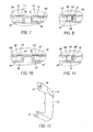
- a flexible handle is provided and can be attached to the housing at approximately the same locations as a rigid handle 32 shown in FIG. 12 can be attached.
- the rigid handle has a pivotable lever 34 at the upper end thereof and an attachment arm 36 at the bottom end thereof.
- the attachment arm 36 is curved downwardly to engage a flange in an attachment recess, indicated generally at 38 in FIG. 5
- the lever 34 has a hook 40 that engages a similar flange to be described that is located at an upper attachment recess; indicated generally at 42 in FIG. 5 .
- the lever 34 can be manipulated by raising a cover 44 that reveals a thumb engaging surface (not shown) which when depressed, causes the lever 34 to be moved upwardly to disengage from a shelf (to be described later) enabling the handle 32 to be removed from the tool 20.
- the flexible handle 30 comprises a long thin strap 50 that is attached to attachment clips 52 on opposite end portions thereof.
- the width of the strap 50 is approximately 3/4 of an inch, but can be wider or narrower as desired.
- the strap is preferably made of a woven fabric that is strong and durable and which preferably does not absorb moisture and may be made of a synthetic material such as nylon or the like.
- Each of the attachment clips 52 and 54 are substantially identical in construction and comprise split base portions 56a and 56b so as to define a gap that facilitates removal of the clip from the housing when desired.
- Each of the base portions 56a and 56b merge into a generally transverse side portion 58 with a bridge portion 60 extending between the side portions.
- a pair of spaced apart prongs 62 extend downwardly from the base portion and each prong has a transverse leg 64, with the transverse legs pointing away from each other and having a beveled surface 66 that tends to deflect the prongs toward each other when the beveled surface 66 engage surfaces of the housing when the attachment clips are inserted into the recesses 38 or 42.
- the bridge portion 60 is narrower than the side portions 58, it has a sufficient cross sectional area so that it is relatively strong and provide the necessary biasing force to keep the prongs 62 biased away from each other to maintain engagement with complimentary structure of the recesses 38 and 42.
- the attachment clips are preferably formed as an integral one piece unit and made of a resilient material that has sufficient strength to support the tool when held by the strap 30 and sufficient strength to keep the prongs in locking engagement with the housing.
- One of the base segments, e.g., 56a, preferably has an L-shaped extension 68 that limits the amount of movement of the sides 58 toward one another when the user squeezes the sides together.
- a number of raised ribs 70 may be provided on the outer surface of each of the sides 58.
- the strap 50 includes a lower end portion 72 that loops around the bridge portion 60 and the two layers of the strap in this area are preferably sewn, riveted or otherwise attached together. At the opposite end portion, the strap 50 extends through a buckle 74, is looped around the bridge portion 60 of the clip 54 and extended back through the buckle 74 as shown. The strap 50 may therefore be adjusted within the buckle 74 to vary the effective length of the handle 30.
- the strap 50 also has a pad portion 76 secured to it, with the strap 50 extending through an opening in a bottom portion 78 of the pad 76.
- the recess 42 has a bottom surface 80, as well as a number of walls 82, 84, 86, 88, 90, 92, 94, 96, 98, 100, 102 and 104, which extend from the bottom surface 80 to the outer surface of the housing 22. While there are a number of decorative bevels at the interface between the outer surface and the walls, the walls are generally perpendicular to the plane of the bottom surface 80, except for the surface 88, which as shown in FIG. 8 , has a significant curvature. As can be seen from the cross-sections of FIGS.
- the walls 82, 94 and 100 have openings 106, 108 and 110 formed therein, respectively, which respectively form shelves 112, 114 and 116 for engagement with the handles 30 or 32.
- walls 82 and 94 are spaced apart from one another and are opposed to each other and are spaced a distance that is slightly less than the distance between the prongs 62 of the attachment clips 52 so that the transverse legs 64 will engage the shelves 112 and 114 to hold the clip 52 in place. If the flexible handle is removed and the rigid handle 32 attached, the edge 40 of the lever 34 will engage the shelf 116 when it is attached to the housing 22.
- attachment recess 38 it is very similar in its construction and the same reference numbers with a prime designation have been given to similar features of it. It should be understood that the arm 36 of the rigid handle 32 engages the shelf 106' when the rigid handle is attached to the tool 20.
Landscapes
- Engineering & Computer Science (AREA)
- Mechanical Engineering (AREA)
- Clamps And Clips (AREA)
- Workshop Equipment, Work Benches, Supports, Or Storage Means (AREA)
- Purses, Travelling Bags, Baskets, Or Suitcases (AREA)
- Portable Power Tools In General (AREA)
Applications Claiming Priority (2)
| Application Number | Priority Date | Filing Date | Title |
|---|---|---|---|
| US10/656,799 US6835032B1 (en) | 2003-09-05 | 2003-09-05 | Rotary power hand tool having a flexible handle and attachment system |
| EP04782151A EP1663585A2 (de) | 2003-09-05 | 2004-08-25 | Kraftbetriebenes drehhandwerkzeug mit flexiblem griff und befestigungssystem |
Related Parent Applications (1)
| Application Number | Title | Priority Date | Filing Date |
|---|---|---|---|
| EP04782151A Division EP1663585A2 (de) | 2003-09-05 | 2004-08-25 | Kraftbetriebenes drehhandwerkzeug mit flexiblem griff und befestigungssystem |
Publications (1)
| Publication Number | Publication Date |
|---|---|
| EP1941976A1 true EP1941976A1 (de) | 2008-07-09 |
Family
ID=33518180
Family Applications (2)
| Application Number | Title | Priority Date | Filing Date |
|---|---|---|---|
| EP04782151A Withdrawn EP1663585A2 (de) | 2003-09-05 | 2004-08-25 | Kraftbetriebenes drehhandwerkzeug mit flexiblem griff und befestigungssystem |
| EP07123372A Withdrawn EP1941976A1 (de) | 2003-09-05 | 2004-08-25 | Rotierendes Leistungshandwerkzeug mit flexiblem Griff und Befestigungssystem |
Family Applications Before (1)
| Application Number | Title | Priority Date | Filing Date |
|---|---|---|---|
| EP04782151A Withdrawn EP1663585A2 (de) | 2003-09-05 | 2004-08-25 | Kraftbetriebenes drehhandwerkzeug mit flexiblem griff und befestigungssystem |
Country Status (5)
| Country | Link |
|---|---|
| US (1) | US6835032B1 (de) |
| EP (2) | EP1663585A2 (de) |
| CA (1) | CA2537857A1 (de) |
| MX (1) | MXPA06002537A (de) |
| WO (1) | WO2005025812A2 (de) |
Families Citing this family (10)
| Publication number | Priority date | Publication date | Assignee | Title |
|---|---|---|---|---|
| US7316528B2 (en) * | 2002-10-15 | 2008-01-08 | Black & Decker Inc. | Ergonomic router assembly |
| US20070074884A1 (en) * | 2005-09-16 | 2007-04-05 | Robert Bosch Gmbh | Shaft lock for power tool |
| JP6162007B2 (ja) * | 2013-02-15 | 2017-07-12 | 株式会社マキタ | 切削工具及びグリップ部 |
| US10045606B2 (en) | 2015-11-02 | 2018-08-14 | Black & Decker Inc. | Impact-absorbing tethering attachment |
| US9968180B2 (en) * | 2016-09-12 | 2018-05-15 | Ty-Flot, Inc. | Drop prevention apparatus and system for hand tools |
| US10531724B2 (en) | 2017-03-29 | 2020-01-14 | Tti (Macao Commercial Offshore) Limited | Belt clip for power tool |
| JP7123592B2 (ja) * | 2018-03-23 | 2022-08-23 | 株式会社マキタ | 電動工具および電動工具の結合具 |
| JP7337530B2 (ja) * | 2019-04-05 | 2023-09-04 | 株式会社マキタ | 動力工具および工具保持具 |
| CN114080667B (zh) * | 2019-05-23 | 2025-08-08 | 恩特格里斯公司 | 用于晶片载体的把手 |
| EP4000812A3 (de) | 2020-10-29 | 2022-08-03 | Black & Decker Inc. | Kordel |
Citations (3)
| Publication number | Priority date | Publication date | Assignee | Title |
|---|---|---|---|---|
| FR2589339A1 (fr) | 1985-11-04 | 1987-05-07 | Michel Jean Louis | Housse de rangement et de transport pour tronconneuses |
| EP1033207A2 (de) | 1999-02-26 | 2000-09-06 | C. & E. FEIN GmbH & Co. | Bügelhalter für ein Handwerkzeug |
| EP1125698A2 (de) | 2000-02-17 | 2001-08-22 | Roto Zip Tool Corporation | Kraftgetriebenes Handwerkzeug |
Family Cites Families (18)
| Publication number | Priority date | Publication date | Assignee | Title |
|---|---|---|---|---|
| US3363510A (en) * | 1966-04-25 | 1968-01-16 | Stanley Works | Router |
| US3487747A (en) * | 1967-03-08 | 1970-01-06 | Stanley Works | Router having cutting tool release means |
| US3466973A (en) * | 1968-01-08 | 1969-09-16 | Singer Co | Rack and pinion depth-of-cut adjusting mechanism for portable routers |
| US3908239A (en) * | 1973-10-18 | 1975-09-30 | Timothy H Gorman | Casting decorative articles |
| US4316685A (en) * | 1980-02-29 | 1982-02-23 | Black & Decker Inc. | Plunge type router |
| US4938642A (en) * | 1988-09-02 | 1990-07-03 | Hitachi Koki Company, Limited | Portable electric router |
| DE4119325A1 (de) * | 1991-06-12 | 1992-12-17 | Licentia Gmbh | Motorisch angetriebenes werkzeug |
| DE4407081C2 (de) * | 1993-03-05 | 1999-03-04 | Makita Corp | Staubdüsenhalterungsaufbau für staub- oder spanabhebende kraftgetriebene Werkzeuge |
| JPH07276261A (ja) * | 1994-04-08 | 1995-10-24 | Hitachi Koki Co Ltd | 差込み式補助ハンドル装置 |
| US5913645A (en) * | 1997-11-04 | 1999-06-22 | S-B Power Tool Company | V-block mounting for fixed-base router with deflection limitation rib |
| EP0962664A1 (de) * | 1998-06-05 | 1999-12-08 | McKechnie UK Limited | Lösbares Befestigungselement |
| US6065912A (en) * | 1998-11-16 | 2000-05-23 | Porter-Cable Corporation | Router switching system |
| US6266850B1 (en) * | 1999-04-16 | 2001-07-31 | Interdynamics, Inc. | Hand-held tool and adjustable handle for same |
| FR2803900B1 (fr) * | 2000-01-17 | 2002-03-15 | Driver | Piece d'accroche, en particulier de panneaux de signaletique pour les magasins |
| DE60143412D1 (de) * | 2000-08-11 | 2010-12-16 | Milwaukee Electric Tool Corp | Oberfräse |
| US6754935B2 (en) * | 2002-06-04 | 2004-06-29 | Credo Technology Corporation | Power tool handle |
| US6732627B2 (en) * | 2002-08-22 | 2004-05-11 | Black & Decker Inc. | Carrying mechanism for power tools |
| DE20318570U1 (de) * | 2003-12-01 | 2004-04-29 | Hess, Markus, Dr. | Griff für ein handgeführtes Arbeitsgerät |
-
2003
- 2003-09-05 US US10/656,799 patent/US6835032B1/en not_active Expired - Fee Related
-
2004
- 2004-08-25 EP EP04782151A patent/EP1663585A2/de not_active Withdrawn
- 2004-08-25 EP EP07123372A patent/EP1941976A1/de not_active Withdrawn
- 2004-08-25 MX MXPA06002537A patent/MXPA06002537A/es active IP Right Grant
- 2004-08-25 WO PCT/US2004/027594 patent/WO2005025812A2/en not_active Ceased
- 2004-08-25 CA CA002537857A patent/CA2537857A1/en not_active Abandoned
Patent Citations (3)
| Publication number | Priority date | Publication date | Assignee | Title |
|---|---|---|---|---|
| FR2589339A1 (fr) | 1985-11-04 | 1987-05-07 | Michel Jean Louis | Housse de rangement et de transport pour tronconneuses |
| EP1033207A2 (de) | 1999-02-26 | 2000-09-06 | C. & E. FEIN GmbH & Co. | Bügelhalter für ein Handwerkzeug |
| EP1125698A2 (de) | 2000-02-17 | 2001-08-22 | Roto Zip Tool Corporation | Kraftgetriebenes Handwerkzeug |
Also Published As
| Publication number | Publication date |
|---|---|
| MXPA06002537A (es) | 2006-06-20 |
| WO2005025812A3 (en) | 2005-06-02 |
| CA2537857A1 (en) | 2005-03-24 |
| WO2005025812A2 (en) | 2005-03-24 |
| US6835032B1 (en) | 2004-12-28 |
| EP1663585A2 (de) | 2006-06-07 |
Similar Documents
| Publication | Publication Date | Title |
|---|---|---|
| US6688407B2 (en) | Belt clip for hand-held power tools | |
| US7143841B2 (en) | Belt clip for hand-held power tools | |
| KR100314368B1 (ko) | 주방도구교환식손잡이 | |
| EP1327500B1 (de) | Gerät zum Eintreiben von Befestigungsmitteln mit modularem Aufbau | |
| US4817221A (en) | Multipurpose survival tool | |
| US8499986B2 (en) | Quick-release arrangement | |
| US6023811A (en) | Modular tool to remove grout | |
| US9126328B2 (en) | Tool holder unit | |
| US7014232B2 (en) | Removable auxiliary handle for tools | |
| US6835032B1 (en) | Rotary power hand tool having a flexible handle and attachment system | |
| EP3381621A1 (de) | Gurtschloss für elektrowerkzeug | |
| JP2005013747A (ja) | クランプオン延長ハンドルを有する手で保持できるモータ付き掃除道具および掃除道具を形成する方法 | |
| US4821418A (en) | Blade holder | |
| US20220379451A1 (en) | Multi-Purpose Tool and Attachments | |
| US4790045A (en) | Power wallpaper removal adapter for jigsaws | |
| US20030101592A1 (en) | Ergonomic handle for scissors | |
| US6192539B1 (en) | Hammer with holder | |
| US6491162B2 (en) | Trowel cover | |
| US4893437A (en) | Power sanding adapter for jigsaws | |
| US20040025277A1 (en) | Smoother with a friction sleeve on handle | |
| EP1535533B1 (de) | Pinsel mit griff und teil mit haaren | |
| JP2005169525A (ja) | 電動工具 | |
| US20190247993A1 (en) | Secondary Handle Attachment | |
| JP2597603Y2 (ja) | 携帯用工具のフック | |
| CA2473431C (en) | Removable auxiliary handle for tools |
Legal Events
| Date | Code | Title | Description |
|---|---|---|---|
| PUAI | Public reference made under article 153(3) epc to a published international application that has entered the european phase |
Free format text: ORIGINAL CODE: 0009012 |
|
| AC | Divisional application: reference to earlier application |
Ref document number: 1663585 Country of ref document: EP Kind code of ref document: P |
|
| AK | Designated contracting states |
Kind code of ref document: A1 Designated state(s): AT BE BG CH CY CZ DE DK EE ES FI FR GB GR HU IE IT LI LU MC NL PL PT RO SE SI SK TR |
|
| 17P | Request for examination filed |
Effective date: 20081022 |
|
| 17Q | First examination report despatched |
Effective date: 20081120 |
|
| AKX | Designation fees paid |
Designated state(s): DE FR GB |
|
| GRAP | Despatch of communication of intention to grant a patent |
Free format text: ORIGINAL CODE: EPIDOSNIGR1 |
|
| RTI1 | Title (correction) |
Free format text: A ROTARY POWER HAND TOOL HAVING A FLEXIBLE HANDLE AND ATTACHMENT SYSTEM |
|
| STAA | Information on the status of an ep patent application or granted ep patent |
Free format text: STATUS: THE APPLICATION IS DEEMED TO BE WITHDRAWN |
|
| 18D | Application deemed to be withdrawn |
Effective date: 20100219 |