EP1942202A2 - Hochdichtes Rhenium mit geringem Sauerstoffgehalt und konsolidierte Pulvermaterialien auf Rhenium-Basis zur Verwendung als Abscheidungsquellen sowie Herstellungsverfahren dafür - Google Patents
Hochdichtes Rhenium mit geringem Sauerstoffgehalt und konsolidierte Pulvermaterialien auf Rhenium-Basis zur Verwendung als Abscheidungsquellen sowie Herstellungsverfahren dafür Download PDFInfo
- Publication number
- EP1942202A2 EP1942202A2 EP08100218A EP08100218A EP1942202A2 EP 1942202 A2 EP1942202 A2 EP 1942202A2 EP 08100218 A EP08100218 A EP 08100218A EP 08100218 A EP08100218 A EP 08100218A EP 1942202 A2 EP1942202 A2 EP 1942202A2
- Authority
- EP
- European Patent Office
- Prior art keywords
- powder
- consolidated
- ppm
- oxygen content
- billet
- Prior art date
- Legal status (The legal status is an assumption and is not a legal conclusion. Google has not performed a legal analysis and makes no representation as to the accuracy of the status listed.)
- Withdrawn
Links
Images


Classifications
-
- C—CHEMISTRY; METALLURGY
- C22—METALLURGY; FERROUS OR NON-FERROUS ALLOYS; TREATMENT OF ALLOYS OR NON-FERROUS METALS
- C22C—ALLOYS
- C22C27/00—Alloys based on rhenium or a refractory metal not mentioned in groups C22C14/00 or C22C16/00
-
- C—CHEMISTRY; METALLURGY
- C22—METALLURGY; FERROUS OR NON-FERROUS ALLOYS; TREATMENT OF ALLOYS OR NON-FERROUS METALS
- C22C—ALLOYS
- C22C1/00—Making non-ferrous alloys
- C22C1/04—Making non-ferrous alloys by powder metallurgy
-
- C—CHEMISTRY; METALLURGY
- C23—COATING METALLIC MATERIAL; COATING MATERIAL WITH METALLIC MATERIAL; CHEMICAL SURFACE TREATMENT; DIFFUSION TREATMENT OF METALLIC MATERIAL; COATING BY VACUUM EVAPORATION, BY SPUTTERING, BY ION IMPLANTATION OR BY CHEMICAL VAPOUR DEPOSITION, IN GENERAL; INHIBITING CORROSION OF METALLIC MATERIAL OR INCRUSTATION IN GENERAL
- C23C—COATING METALLIC MATERIAL; COATING MATERIAL WITH METALLIC MATERIAL; SURFACE TREATMENT OF METALLIC MATERIAL BY DIFFUSION INTO THE SURFACE, BY CHEMICAL CONVERSION OR SUBSTITUTION; COATING BY VACUUM EVAPORATION, BY SPUTTERING, BY ION IMPLANTATION OR BY CHEMICAL VAPOUR DEPOSITION, IN GENERAL
- C23C14/00—Coating by vacuum evaporation, by sputtering or by ion implantation of the coating forming material
- C23C14/22—Coating by vacuum evaporation, by sputtering or by ion implantation of the coating forming material characterised by the process of coating
- C23C14/34—Sputtering
- C23C14/3407—Cathode assembly for sputtering apparatus, e.g. Target
- C23C14/3414—Metallurgical or chemical aspects of target preparation, e.g. casting, powder metallurgy
-
- B—PERFORMING OPERATIONS; TRANSPORTING
- B22—CASTING; POWDER METALLURGY
- B22F—WORKING METALLIC POWDER; MANUFACTURE OF ARTICLES FROM METALLIC POWDER; MAKING METALLIC POWDER; APPARATUS OR DEVICES SPECIALLY ADAPTED FOR METALLIC POWDER
- B22F2998/00—Supplementary information concerning processes or compositions relating to powder metallurgy
- B22F2998/10—Processes characterised by the sequence of their steps
-
- B—PERFORMING OPERATIONS; TRANSPORTING
- B22—CASTING; POWDER METALLURGY
- B22F—WORKING METALLIC POWDER; MANUFACTURE OF ARTICLES FROM METALLIC POWDER; MAKING METALLIC POWDER; APPARATUS OR DEVICES SPECIALLY ADAPTED FOR METALLIC POWDER
- B22F2999/00—Aspects linked to processes or compositions used in powder metallurgy
Definitions
- the present disclosure relates generally to high density, low oxygen content Re and Re-based materials (such as alloys and metal-ceramics) and their method of manufacture.
- the present disclosure enjoys particular utility in the fabrication of deposition sources, e.g., sputtering targets, comprising Re and Re-based materials utilized in the deposition of thin film layers in the manufacture of data storage media, e.g., magnetic recording media.
- Ruthenium (Ru) is present only in limited amounts in nature and thus the demand for Ru and Ru-based materials, e.g., alloys, such as are commonly utilized in substantial volume in the manufacture of thin film data storage media, e.g., magnetic recording media, exceeds their supply.
- FIG. 1 An example of a typical thin film perpendicular recording system 20 containing a Ru or Ru-based layer and comprising a vertically oriented magnetic recording medium 21 with a relatively thick soft magnetic underlayer, a relatively thin hard magnetic recording layer, and a single-pole head, is illustrated in FIG. 1 , wherein reference numerals 10, 11A, 4, 5, and 6 respectively indicate a non-magnetic substrate, an adhesion layer (optional), a soft magnetic underlayer, at least one non-magnetic interlayer, and at least one perpendicular hard magnetic recording layer. Reference numerals 7 and 8 , respectively, indicate the single and auxiliary poles of a single-pole magnetic transducer head 16 .
- the relatively thin interlayer 5 (also referred to as an "intermediate" layer and described in more detail below) underlying the at least one magnetically hard recording layer 6 is comprised of one or more layers of non-magnetic or substantially non-magnetic materials, typically Ru or a Ru-based alloy, and serves to (1) prevent magnetic interaction between the soft underlayer 4 and the at least one hard recording layer 6 and (2) promote desired microstructural and magnetic properties of the at least one magnetically hard recording layer 6 .
- flux ⁇ is seen as emanating from single pole 7 of single-pole magnetic transducer head 16 , entering and passing through the at least one vertically oriented, hard magnetic recording layer 6 in the region below single pole 7, entering and traveling within soft magnetic underlayer 4 for a distance, and then exiting therefrom and passing through the at least one perpendicular hard magnetic recording layer 6 in the region below auxiliary pole 8 of single-pole magnetic transducer head 16 .
- the direction of movement of perpendicular magnetic medium 21 past transducer head 16 is indicated in the figure by the arrow above medium 21 .
- vertical lines 9 indicate grain boundaries of polycrystalline layers 5 and 6 of the layer stack constituting medium 21 .
- Magnetically hard main recording layer 6 is formed on interlayer 5, and while the grains of each polycrystalline layer may be of differing widths (as measured in a horizontal direction) represented by a grain size distribution, they are generally in vertical registry (i.e., vertically "correlated" or aligned).
- a protective overcoat layer 14 such as of a diamond-like carbon (DLC), formed over hard magnetic layer 6
- a lubricant topcoat layer 15 such as of a perfluoropolyethylene material, formed over the protective overcoat layer.
- Substrate 10 is typically disk-shaped and comprised of a non-magnetic metal or alloy, e.g., Al or an Al-based alloy, such as Al-Mg having an Ni-P plating layer on the deposition surface thereof, or substrate 10 is comprised of a suitable glass, ceramic, glass-ceramic, polymeric material, or a composite or laminate of these materials.
- Optional adhesion layer 11A if present, may comprise an up to about 40 ⁇ thick layer of a material such as Ti or a Ti alloy.
- Soft magnetic underlayer 4 is typically comprised of an about 500 to about 4,000 ⁇ thick layer of a soft magnetic material selected from the group consisting of Ni, NiFe (Permalloy), Co, CoZr, CoZrCr, CoZrNb, CoFeZrNb, CoFe, Fe, FeN, FeSiAl, FeSiAlN, FeCoB, FeCoC, etc.
- a soft magnetic material selected from the group consisting of Ni, NiFe (Permalloy), Co, CoZr, CoZrCr, CoZrNb, CoFeZrNb, CoFe, Fe, FeN, FeSiAl, FeSiAlN, FeCoB, FeCoC, etc.
- Interlayer 5 located beneath the magnetically hard recording layer 6 plays a critical role (see below) in the formation of certain types of media, e.g., granular perpendicular magnetic recording media exhibiting optimum recording and stability performance, and typically comprises an up to about 300 ⁇ thick layer or layers of non-magnetic material(s), such as Ru, TiCr, Ru/CoCr 37 Pt 6 , RuCr/CoCrPt, etc.
- non-magnetic material(s) such as Ru, TiCr, Ru/CoCr 37 Pt 6 , RuCr/CoCrPt, etc.
- the at least one magnetically hard recording layer 6 has perpendicular magnetic anisotropy, is typically comprised of an about 100 to about 250 ⁇ thick layer(s) of Co-based alloy(s) including one or more elements selected from the group consisting of Cr, Fe, Ta, Ni, Mo, Pt, V, Nb, Ge, B, and Pd, iron nitrides or oxides, and is generally formed (e.g., as by sputter deposition) on a non-magnetic (or at most weakly magnetic), crystalline interlayer 5 , typically a hcp-structured layer which enhances the Co ⁇ 0002> crystalline texture of the overlying Co-based granular magnetic recording layer 6 perpendicular to the to the film plane, thereby resulting in very high perpendicular anisotropy.
- interlayer 5 is essential in the formation of granular perpendicular magnetic recording media exhibiting optimum recording and stability performance.
- Ru and/or Ru-based alloy interlayer 5 Notwithstanding the critical role played by the Ru and/or Ru-based alloy interlayer 5 in the manufacture of high performance data storage applications, e.g., granular perpendicular magnetic recording media such as described above, the constantly increasing demand for Ru and its alloys exceeds the Ru supply capacity and therefore necessitates development of other, more abundant and thus less costly non-magnetic materials useful in the formation of interlayers of magnetic recording media.
- rhenium (Re) and Re-based materials e.g., Re-based alloys, have attracted attention as potential replacements for Ru and its alloys for use as thin film deposition sources, e.g., sputtering targets.
- An advantage of the present disclosure is improved methodology for forming high density, low oxygen content consolidated powder materials comprising Re and Re-containing materials.
- a further advantage of the present disclosure is improved methodology for forming deposition sources, e.g., sputtering targets, comprising high density, low oxygen content consolidated powder materials comprising Re and Re-containing materials.
- Another advantage of the present disclosure is improved, high density, low oxygen content consolidated powder materials comprising Re and Re-containing materials.
- Yet another advantage of the present disclosure is improved deposition sources, e.g., sputtering targets, comprising high density, low oxygen content consolidated powder materials comprising Re and Re-containing materials.
- step (e) comprises consolidating the green billet and forming a consolidated material with greater than about 99 % of theoretical density and low oxygen content below about 100 ppm for Re and below about 200 ppm for Re-based materials formed from the mixture, excluding oxygen from non-metallic compounds and/or ceramics.
- the method further comprises a step of:
- step (c) comprises forming a billet comprising the degassed Re powder or the mixture, as by cold isostatic pressing (CIP) or cold mechanical pressing; and step (d) comprises maintaining the billet at an elevated temperature while contacting the billet with H 2 gas.
- CIP cold isostatic pressing
- step (d) comprises maintaining the billet at an elevated temperature while contacting the billet with H 2 gas.
- step (e) comprises steps of: (e 1 ) encapsulating the billet in a container; and (e 2 ) subjecting the encapsulated billet to hot isostatic pressing (HIP) to form the consolidated material; whereas according to other embodiments of the present disclosure, step (e) comprises steps of: (e 1 ) subjecting the billet to vacuum hot pressing (VHP) or spark plasma sintering (SPS) to achieve ⁇ - 97 % of theoretical density; and (e 2 ) subjecting the thus-treated billet to hot isostatic pressing (HIP) to form the consolidated material with > ⁇ 97 % of theoretical density.
- VHP vacuum hot pressing
- SPS spark plasma sintering
- step (a) comprises providing a Re powder starting material; and step (e) comprises forming a consolidated Re material having 100 % of theoretical density and oxygen content below about 100 ppm; whereas, according to other embodiments of the present disclosure, step (a) comprises providing a Re powder starting material and a predetermined amount of at least one additional powder material comprising at least one transition metal element X; and step (e) comprises forming a consolidated material of formula Re-X, comprising predetermined proportions of Re and the at least one transition metal.
- step (a) comprises providing a predetermined amount at least one additional powder material comprising at least one transition metal selected from the group consisting of Mo, Co, Ru, W, and Cr; and step (e) comprises forming a consolidated Re-X material having greater than about 99.0 % of theoretical density, oxygen content below about 200 ppm, a Re phase, an X phase, and a Re-X phase.
- step (a) comprises providing a Re powder starting material and a predetermined amount of at least one additional powder material comprising at least one material Y selected from the group consisting of non-metallic elements, non-metallic compounds, and ceramic materials; and step (e) comprises forming a consolidated material of formula Re-Y, comprising predetermined proportions of Re and the at least one non-metallic element, non-metallic compound, or ceramic material.
- Y is at least one carbide or nitride or an oxide of Ti, Si, or Mg.
- step (a) comprises providing a predetermined amount of Re powder starting material, a predetermined amount of at least one additional powder material comprising at least one transition metal element X, and a predetermined amount of at least one additional powder material comprising at least one material Y selected from the group consisting of non-metallic elements, non-metallic compounds, and ceramic materials; and step (e) comprises forming a consolidated material of formula Re-X-Y, comprising predetermined proportions of Re, the at least one transition metal element X, and the at least one non-metallic element, non-metallic compound, or ceramic material Y.
- X is at least one transition metal selected from the group consisting of Mo, Co, Ru, W, and Cr
- Y is at least one carbide or nitride or an oxide of Ti, Si, or Mg.
- Embodiments of the present disclosure include those wherein steps (c) - (e) are replaced by a single step process, e.g., a process selected from the group consisting of: vacuum hot pressing (VHP), spark plasma sintering (SPS), microwave sintering, atmospheric pressure H 2 sintering, and vacuum H 2 sintering.
- VHP vacuum hot pressing
- SPS spark plasma sintering
- microwave sintering atmospheric pressure H 2 sintering
- atmospheric pressure H 2 sintering atmospheric pressure
- vacuum H 2 sintering vacuum H 2 sintering
- Another aspect of the present disclosure is an improved deposition source comprising consolidated Re powder material having greater than about 95 % of theoretical density and oxygen content below about 200 ppm, preferably greater than about 99 % of theoretical density and oxygen content below about 100 ppm, more preferably 100 % of theoretical density.
- a further aspect of the present disclosure is an improved deposition source comprising consolidated Re-X powder material, where X is at least one transition metal element, the consolidated Re-X powder material having greater than about 95 % of theoretical density, oxygen content below about 500 ppm, a Re phase, an X phase, and a Re-X phase.
- the consolidated Re-X powder material has greater than about 99 % of theoretical density and oxygen content below about 200 ppm.
- Transition metal element X is preferably selected from the group consisting of Mo, Co, Ru, W, and Cr.
- Still another aspect of the present disclosure is an improved deposition source comprising consolidated Re-Y powder material, where Y is at least one non-metallic element, non-metallic compound, or ceramic material, the consolidated Re-Y powder material having greater than about 95 % of theoretical density and oxygen content below about 500 ppm, excluding oxygen from non-metallic compounds and/or ceramics, preferably greater than about 99 % of theoretical density and oxygen content below about 200 ppm, excluding oxygen from non-metallic compounds and/or ceramics.
- Y is preferably at least one carbide or nitride or oxide ofTi, Si, and Mg.
- an improved deposition source comprising consolidated Re-X-Y powder material, where X is at least one transition metal element and Y is at least one non-metallic element, non-metallic compound, or ceramic material, the consolidated Re-X-Y powder material having greater than about 95 % of theoretical density and oxygen content below about 500 ppm, excluding oxygen from non-metallic compounds and/or ceramics, preferably greater than about 99 % of theoretical density and oxygen content below about 200 ppm, excluding oxygen from non-metallic compounds and/or ceramics.
- the at least one transition metal element X is selected from the group consisting of Mo, Co, Ru, W, and Cr; and Y is at least one carbide or nitride or an oxide of Ti, Si, or Mg.
- FIG. 1 schematically illustrates, in simplified cross-sectional view, a portion of a magnetic recording storage, and retrieval system comprised of a perpendicular magnetic recording medium and a single pole transducer head;
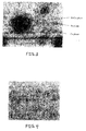
- FIGS. 2 and 3 are micrographs showing the microstructure of a sputtering target comprising Re - 50 at. % Co consolidated powder material formed according to an embodiment of the present disclosure
- FIG. 4 is a micrograph showing the microstructure of a sputtering target comprising Re - 15 at. % Mo consolidated powder material formed according to another embodiment of the present disclosure
- FIG. 5 is a micrograph showing the microstructure of a sputtering target comprising Re - 20 at. % W consolidated powder material formed according to yet another embodiment of the present disclosure
- FIG. 6 is a micrograph showing the microstructure of a sputtering target comprising Re - 25 at. % Cr consolidated powder material formed according to still another embodiment of the present disclosure.
- FIG. 7 is a micrograph showing the microstructure of a sputtering target comprising Re - 50 at. % Ru consolidated powder material formed according to a further embodiment of the present disclosure.
- the present disclosure has as an aim provision of improved Re and Re-based materials for use, inter alia, as thin film layers in the manufacture of stable, high performance, high areal recording density magnetic recording media, e.g., granular perpendicular magnetic recording media.
- a key requirement for obtaining such high performance media is formation of magnetically hard granular perpendicular recording layers with well-isolated, fine grain structure coupled with large perpendicular magnetic anisotropy K u .
- the granular perpendicular magnetic recording layer is usually deposited on a non-magnetic or weakly magnetic, crystalline hcp -based interlayer, typically a Ru or Ru-based alloy layer, which enhances the Co ⁇ 0002> texture of the Co-based magnetically hard recording layer perpendicular to the film plane, thus leading to high perpendicular magnetic anisotropy K u .
- the present disclosure is based upon recognition that Re and Re-based layers, in view of the relative abundance of Re vis-à-vis Ru, the hcp crystal structure of Re and Re-based materials at room temperature, and relative inertness leading to resistance to oxide formation at its interface with oxygen-containing granular perpendicular magnetic alloy layers, make them excellent, economically viable candidates for replacement of Ru and Ru-based alloy materials as interlayers in the formation of magnetic recording media, particularly granular perpendicular media.
- the interlayer of granular perpendicular magnetic recording media functions not only to enhance the crystallographic texturing of the overlying granular magnetic recording layer, but can also contribute to its grain size refinement when the latter is epitaxially grown on an interlayer with refined grain sizes. Further, close lattice matching between the interlayer and the overlying granular recording layer ensures formation of a substantially defect-free interface therebetween, reducing likelihood of in-plane magnetization.
- the Re and Re-based materials possess:
- Re and Re-based materials contemplated by the present disclosure include:
- key steps according to the instant methodology for forming high density, low oxygen content Re and Re-based materials for use as deposition sources include:
- step 2 for consolidating the green material comprises performing a plurality of steps, including in sequence:
- a billet of degassed green material is encapsulated in a container and then subjected to hot isostatic pressing (HIP); whereas, according to a second alternative procedure for consolidating the further degassed material, a billet of degassed green material is subjected to vacuum hot pressing (VHP) or spark plasma sintering (SPS) to achieve ⁇ ⁇ 97 % of theoretical density and then the thus-treated billet is subjected to hot isostatic pressing (HIP) to form the consolidated material with > ⁇ 97 % of theoretical density.
- VHP vacuum hot pressing
- SPS spark plasma sintering
- step 2 for consolidation of the degassed green material is performed by an alternative method, such that steps 2A - 2C are replaced with a single step performed, e.g., by vacuum hot pressing (VHP), spark plasma sintering (SPS), microwave sintering, atmospheric pressure H 2 sintering, or vacuum H 2 sintering.
- VHP vacuum hot pressing
- SPS spark plasma sintering
- microwave sintering atmospheric pressure H 2 sintering
- atmospheric pressure H 2 sintering atmospheric pressure H 2 sintering
- vacuum H 2 sintering vacuum hot pressing
- the particle size distribution (PSD) of the raw powder provided in step 1 is typically -200 mesh, although smaller and larger mesh powders such as -100 mesh and -325 mesh may also be utilized.
- the tap density and bulk density of raw Re powder obtained via chemical reduction processing are 2.86 gm/cm 3 and 1.63 gm/cm 3 , respectively, and the oxygen content is typically > ⁇ 1000 ppm, which must be reduced to ⁇ ⁇ 1000 ppm, e.g., as low as about 100 ppm (depending upon the specification of the resultant deposition source, e.g., a sputtering target).
- the powders of any metal of non-metal additive constituents (X and/or Y) to be added to the raw Re powder should have a PSD similar to that of the raw Re powder.
- the PSD of the powder(s) of the X and/or Y additive constituents may be larger or smaller than that of the raw Re powder, depending upon the desired composition of the ultimate Re-based material, as well as upon other properties such as density, particle shape, etc.
- the powders of the X and/or Y additive constituents should also have a low oxygen content, typically ⁇ 500 ppm, but which can be lower or higher depending upon the requisite oxygen content of the resultant target, the powder properties, and its proportion (e.g., at. %) in the resultant target.
- the raw Re powder and the powder(s) of the X and/or Y additive constituents are weighed out in predetermined amounts (for achieving products having desired constituent proportions) and then blended together, as in a tumbling blender, for a sufficient interval for obtaining good mixing, i.e., typically within 15 - 60 min., although shorter or longer blending times are possible as necessary.
- Densification of the degassed pure Re powder or blended Re (X and/or Y) powders according to step 2A to form an increased density degassed green powder material may, for example, be accomplished by cold isostatic pressing (CIP) or mechanical pressing, e.g., as by loading the degassed powder or blended powder into a CIP bag or die under an inert atmosphere and performing CIP or mechanical pressing at a pressure between about 20 and about 60 ksi to achieve a green density > ⁇ 50 %.
- CIP cold isostatic pressing
- mechanical pressing e.g., as by loading the degassed powder or blended powder into a CIP bag or die under an inert atmosphere and performing CIP or mechanical pressing at a pressure between about 20 and about 60 ksi to achieve a green density > ⁇ 50 %.
- step 2B when the resultant deposition source is required to have an ultra-low oxygen content, the billet formed by CIP or cold mechanical pressing in step 2A requires further degassing treatment, as in a H 2 furnace or vacuum oven, to reduce/remove any oxygen on the powder surfaces picked up during previous powder handling, and to further reduce the oxygen content within the powder particles.
- Control of the degassing temperatures and intervals (which will vary according to the composition of the pressed billet) to optimum values is necessary in order to reduce/remove the oxygen without causing premature sintering and closing off of pores of the powder (as at excessively high temperatures) or obtaining insufficient oxygen removal (as at too low temperatures).
- pre-sintering density of the billet should not exceed about 92 %.
- suitable temperatures for performing H 2 degassing treatment are: 850 °C for Re-Co; 950 °C for Re-Ru, and 1050 °C for pure Re, Re-Mo, and Re-W.
- Step 2B may be skipped when the oxygen content of the resultant Re or Re-based deposition source (e.g., sputtering target) is not too low, or when the oxygen content of the raw or degassed green powder is sufficiently low.
- the resultant Re or Re-based deposition source e.g., sputtering target
- Step 2C comprises loading the billet into a suitable metal or metal alloy can, e.g., a low carbon steel (LCS) can coated with alumina (Al 2 O 3 ) or a Ti can (with or without a coating), heating the can, evacuating the can to achieve a vacuum, and sealing the can.
- Hot isostatic pressing (HIP) is then performed to consolidate the billet.
- the temperature utilized for HIP is generally above about 1000 °C but will depend upon the composition of the billet; the pressure will range from about 15 to about 45 ksi, and the HIP interval generally is in the range of several hours, e.g., 4 - 10 hrs.
- Step 3 comprises sectioning the consolidated HIP billet by any suitable method, e.g., electrical discharge machining (EDM), into slices of desired thickness, followed by machining to final deposition source (e.g., sputtering target) dimensions.
- EDM electrical discharge machining
- a Re - 50 at. % Co sputtering target was fabricated according to the following procedure:
- a -325 mesh reduced Re powder with as-supplied oxygen content of about 2200 ppm was degassed at a peak temperature of 1050 °C under a H 2 atmosphere in a vacuum furnace to reduce the oxygen content to ⁇ ⁇ 120 ppm.
- the degassed Re powder was then blended with an appropriate amount of -100 mesh Co powder for about 45 min. in a tumbler-type blender, and the blended powder subjected to CIP at about 55 ksi.
- the resulting CIP billet was degassed in a H 2 atmosphere at a peak temperature of about 850 °C, followed by encapsulation in a can and evacuation and sealing of the can.
- the encapsulated CIP billet was then subjected to HIP at a peak temperature of 1236 °C and 29 ksi pressure, and final targets of desired dimensions were machined from the consolidated HIP billet.
- the density of the resultant sputtering target material was 100 % of theoretical, oxygen content was 66 ppm, and micrographic examination (see FIGS. 2 - 3 ) revealed the presence of three (3) distinct phases in the resultant Re-Co alloy, namely: a pure Re phase, a pure Co phase, and a minor amount of a Re-Co phase.
- a Re - 15 at. % Mo sputtering target was fabricated according to the following procedure:
- a -325 mesh reduced Re powder with as-supplied oxygen content of about 2200 ppm was degassed at a peak temperature of 1050 °C under a H 2 atmosphere in a vacuum furnace to reduce the oxygen content to ⁇ ⁇ 120 ppm.
- the degassed Re powder was then blended with an appropriate amount of -325 mesh Mo powder for about 45 min. in a tumbler-type blender, and the blended powder subjected to CIP at about 55 ksi.
- the resulting CIP billet was degassed in a H 2 atmosphere at a peak temperature of about 1050 °C, followed by encapsulation in a can and evacuation and sealing of the can.
- the encapsulated CIP billet was then subjected to HIP at a peak temperature of 1515 °C and 29 ksi pressure, and final targets of desired dimensions were machined from the consolidated HIP billet.
- the density of the resultant sputtering target material was 99.3 % of theoretical, oxygen content was 108 ppm, and micrographic examination (see FIG. 4 ) revealed the presence of distinct Re and Mo phases, the Re phases corresponding to the lighter areas in FIG. 4 .
- a pure (i.e., 100 %) Re sputtering target was fabricated according to the following procedure:
- a -200 mesh reduced Re powder was degassed at a peak temperature of 1050 °C under a H 2 atmosphere in a vacuum furnace to reduce the oxygen content to ⁇ ⁇ 120 ppm.
- the degassed Re powder was then homogenized for about 10 min. in a tumbler-type blender, and the homogenized powder subjected to CIP at about 55 ksi.
- the resulting CIP billet was degassed in a H 2 atmosphere at a peak temperature of about 1050 °C, followed by encapsulation in a can and evacuation and sealing of the can.
- the encapsulated CIP billet was then subjected to HIP at a peak temperature of 1515 °C and 29 ksi pressure, and final targets of desired dimensions were machined from the consolidated HIP billet.
- the density of the resultant pure Re sputtering target material was 100 % of theoretical, and the oxygen content was 47 ppm.
- a Re - 20 at. % W sputtering target was fabricated according to the following procedure:
- a -200 mesh reduced Re powder was degassed at a peak temperature of 1050 °C under a H 2 atmosphere in a vacuum furnace to reduce the oxygen content to ⁇ ⁇ 120 ppm.
- the degassed Re powder was then blended with an appropriate amount of -325 mesh W powder for about 45 min. in a tumbler-type blender, and the blended powder subjected to CIP at about 55 ksi.
- the resulting CIP billet was degassed in a H 2 atmosphere at a peak temperature of about 1050 °C, followed by encapsulation in a can and evacuation and sealing of the can.
- the encapsulated CIP billet was then subjected to HIP at a peak temperature of 1515 °C and 29 ksi pressure, and final targets of desired dimensions were machined from the consolidated HIP billet.
- the density of the resultant sputtering target material was 99.5 % of theoretical, oxygen content was 65 ppm, and micrographic examination (see FIG. 5 ) revealed the presence of distinct Re and W phases, the Re phases corresponding to the lighter areas in FIG. 5 .
- a Re - 25 at. % Cr sputtering target was fabricated according to the following procedure:
- a -200 mesh reduced Re powder was degassed at a peak temperature of 1050 °C under a H 2 atmosphere in a vacuum furnace to reduce the oxygen content to ⁇ ⁇ 120 ppm.
- the degassed Re powder was then blended with an appropriate amount of -325 mesh Cr powder for about 45 min. in a tumbler-type blender, and the blended powder subjected to CIP at about 55 ksi.
- the resulting CIP billet was degassed in a H 2 atmosphere at an elevated temperature, followed by encapsulation in a can and evacuation and sealing of the can.
- the encapsulated CIP billet was then subjected to HIP at a peak temperature of 1450 °C and 29 ksi pressure, and final targets of desired dimensions were machined from the consolidated HIP billet.
- the density of the resultant sputtering target material was 99.2 % of theoretical, oxygen content was 162 ppm, and micrographic examination (see FIG. 6 ) revealed the presence of three (3) distinct phases, i.e., a pure Re phase, a pure Cr phase, and a Re-Cr phase.
- a Re - 50 at. % Ru sputtering target was fabricated according to the following procedure:
- a -200 mesh reduced Re powder was degassed at a peak temperature of 1050 °C under a H 2 atmosphere in a vacuum furnace to reduce the oxygen content to ⁇ ⁇ 120 ppm.
- the degassed Re powder was then blended with an appropriate amount of -325 mesh Ru powder (degassed to oxygen content ⁇ ⁇ 200 ppm) for about 45 min. in a tumbler-type blender, and the blended powder subjected to CIP at about 55 ksi.
- the resulting CIP billet was degassed in a H 2 atmosphere at a peak temperature of about 950 °C, followed by encapsulation in a can and evacuation and sealing of the can.
- the encapsulated CIP billet was then subjected to HIP at a peak temperature of 1515 °C and 29 ksi pressure, and final targets of desired dimensions were machined from the consolidated HIP billet.
- the density of the resultant sputtering target material was 100 % of theoretical, oxygen content was 102 ppm, and micrographic examination (see FIG. 7 ) revealed the presence of three (3) distinct phases, i.e., a pure Re phase, a pure Ru phase, and a Re-Ru phase.
- the present disclosure provides improved methodology for forming high density, low oxygen content Re and Re-based materials and deposition sources comprising same, e.g., sputtering targets, which Re and Re-based alloy targets are particularly useful in the formation of crystalline interlayers in layer stacks of thin film, Co-based granular perpendicular magnetic recording media.
- the enhanced magnetic recording layers afforded by the present disclosure facilitate manufacture of high performance, high areal recording density granular perpendicular magnetic recording media with improved signal-to-noise ratio (SNR) and increased perpendicular magnetic anisotropy.
- SNR signal-to-noise ratio
Landscapes
- Chemical & Material Sciences (AREA)
- Engineering & Computer Science (AREA)
- Materials Engineering (AREA)
- Mechanical Engineering (AREA)
- Metallurgy (AREA)
- Organic Chemistry (AREA)
- Chemical Kinetics & Catalysis (AREA)
- Powder Metallurgy (AREA)
- Physical Vapour Deposition (AREA)
Applications Claiming Priority (3)
| Application Number | Priority Date | Filing Date | Title |
|---|---|---|---|
| US87941807P | 2007-01-08 | 2007-01-08 | |
| US90763307P | 2007-04-13 | 2007-04-13 | |
| US11/969,172 US20080166255A1 (en) | 2007-01-08 | 2008-01-03 | High density, low oxygen re and re-based consolidated powder materials for use as deposition sources & methods of making same |
Publications (2)
| Publication Number | Publication Date |
|---|---|
| EP1942202A2 true EP1942202A2 (de) | 2008-07-09 |
| EP1942202A3 EP1942202A3 (de) | 2010-09-29 |
Family
ID=39278280
Family Applications (1)
| Application Number | Title | Priority Date | Filing Date |
|---|---|---|---|
| EP08100218A Withdrawn EP1942202A3 (de) | 2007-01-08 | 2008-01-08 | Hochdichtes Rhenium mit geringem Sauerstoffgehalt und konsolidierte Pulvermaterialien auf Rhenium-Basis zur Verwendung als Abscheidungsquellen sowie Herstellungsverfahren dafür |
Country Status (1)
| Country | Link |
|---|---|
| EP (1) | EP1942202A3 (de) |
Cited By (3)
| Publication number | Priority date | Publication date | Assignee | Title |
|---|---|---|---|---|
| CN105642899A (zh) * | 2014-11-20 | 2016-06-08 | 宁波江丰电子材料股份有限公司 | 钼硅靶材的制造方法 |
| CN106735280A (zh) * | 2016-11-23 | 2017-05-31 | 西北有色金属研究院 | 一种球形TiTa合金粉末的制备方法 |
| CN117047100A (zh) * | 2023-07-12 | 2023-11-14 | 中国航发北京航空材料研究院 | 一种降低含湿高温合金粉末氧含量的精确定制处理工艺 |
Family Cites Families (11)
| Publication number | Priority date | Publication date | Assignee | Title |
|---|---|---|---|---|
| US6119485A (en) * | 1997-02-21 | 2000-09-19 | Matsushita Electric Industrial Co., Ltd. | Press-molding die, method for manufacturing the same and glass article molded with the same |
| JP2001020065A (ja) * | 1999-07-07 | 2001-01-23 | Hitachi Metals Ltd | スパッタリング用ターゲット及びその製造方法ならびに高融点金属粉末材料 |
| JP4503817B2 (ja) * | 2000-11-30 | 2010-07-14 | 株式会社東芝 | スパッタリングターゲットおよび薄膜 |
| JP4757400B2 (ja) * | 2001-05-09 | 2011-08-24 | 昭和電工株式会社 | 垂直磁気記録媒体、および磁気記録再生装置 |
| JP2003226964A (ja) * | 2002-02-05 | 2003-08-15 | Nippon Steel Corp | スパッタリング用タングステンターゲットの製造方法 |
| JP4042095B2 (ja) * | 2002-03-08 | 2008-02-06 | 日立金属株式会社 | 高純度金属粉の製造方法および高純度金属粉の製造装置 |
| US7135141B2 (en) * | 2003-03-31 | 2006-11-14 | Hitachi Metals, Ltd. | Method of manufacturing a sintered body |
| DE102004020404B4 (de) * | 2004-04-23 | 2007-06-06 | H. C. Starck Gmbh & Co. Kg | Trägerplatte für Sputtertargets, Verfahren zu ihrer Herstellung und Einheit aus Trägerplatte und Sputtertarget |
| US20060165547A1 (en) * | 2005-01-26 | 2006-07-27 | Honeywell International, Inc. | High strength rhenium alloys and high temperature components made from such alloys |
| US20060237303A1 (en) * | 2005-03-31 | 2006-10-26 | Hoya Corporation | Sputtering target, method of manufacturing a multilayer reflective film coated substrate, method of manufacturing a reflective mask blank, and method of manufacturing a reflective mask |
| WO2006134743A1 (ja) * | 2005-06-16 | 2006-12-21 | Nippon Mining & Metals Co., Ltd. | ルテニウム合金スパッタリングターゲット |
-
2008
- 2008-01-08 EP EP08100218A patent/EP1942202A3/de not_active Withdrawn
Cited By (5)
| Publication number | Priority date | Publication date | Assignee | Title |
|---|---|---|---|---|
| CN105642899A (zh) * | 2014-11-20 | 2016-06-08 | 宁波江丰电子材料股份有限公司 | 钼硅靶材的制造方法 |
| CN105642899B (zh) * | 2014-11-20 | 2018-11-27 | 宁波江丰电子材料股份有限公司 | 钼硅靶材的制造方法 |
| CN106735280A (zh) * | 2016-11-23 | 2017-05-31 | 西北有色金属研究院 | 一种球形TiTa合金粉末的制备方法 |
| CN106735280B (zh) * | 2016-11-23 | 2019-05-28 | 西北有色金属研究院 | 一种球形TiTa合金粉末的制备方法 |
| CN117047100A (zh) * | 2023-07-12 | 2023-11-14 | 中国航发北京航空材料研究院 | 一种降低含湿高温合金粉末氧含量的精确定制处理工艺 |
Also Published As
| Publication number | Publication date |
|---|---|
| EP1942202A3 (de) | 2010-09-29 |
Similar Documents
| Publication | Publication Date | Title |
|---|---|---|
| JP4175829B2 (ja) | 記録媒体用スパッタリングターゲットと磁気記録媒体 | |
| US20080166596A1 (en) | Re-based alloys usable as deposition targets for forming interlayers in granular perpendicular magnetic recording media & media utilizing said alloys | |
| JP5226155B2 (ja) | Fe−Pt系強磁性材スパッタリングターゲット | |
| CN101161854B (zh) | Co—Fe—Zr系合金溅射靶材及其制造方法 | |
| US20090120237A1 (en) | Enhanced formulation of cobalt alloy matrix compositions | |
| TWI663262B (zh) | Ni-based sputtering target and magnetic recording medium | |
| JP2007128630A (ja) | 磁気記録媒体、磁気記録媒体製造方法及びスパッタターゲット | |
| EP1942202A2 (de) | Hochdichtes Rhenium mit geringem Sauerstoffgehalt und konsolidierte Pulvermaterialien auf Rhenium-Basis zur Verwendung als Abscheidungsquellen sowie Herstellungsverfahren dafür | |
| JP5195868B2 (ja) | 垂直磁気記録媒体の製造方法 | |
| JP2006313584A (ja) | 磁気記録媒体の製造方法 | |
| US20080166255A1 (en) | High density, low oxygen re and re-based consolidated powder materials for use as deposition sources & methods of making same | |
| EP1211674A1 (de) | Magnetisches aufzeichungsmittel, herstellungsverfahren hierfür und magnetischer aufzeichnungsapparat | |
| US20110129692A1 (en) | Magnetic alloy materials with hcp stabilized microstructure, magnetic recording media comprising same, and fabrication method therefor | |
| US20070285839A1 (en) | Perpendicular magnetic recording medium and method of manufacturing the same | |
| EP1956106A2 (de) | Re-basierte Legierungen zur Verwendung als Ablagerungsziele zur Formung von Zwischenschichten in granularen Pendelmagnetaufzeichnungsmedien und Medien mit solchen Legierungen | |
| TWI724428B (zh) | 濺鍍靶、顆粒膜及垂直磁記錄媒體 | |
| KR20080065242A (ko) | 침착원으로 사용하기 위한 고밀도, 저산소 Re 및 Re계압분체 재료 그리고 그 제조방법 | |
| JP7834184B2 (ja) | スパッタリングターゲット、積層膜の製造方法、積層膜、及び磁気記録媒体 | |
| TWI839898B (zh) | Fe-Pt-C系濺射靶部件、濺射靶組件、成膜方法、以及濺射靶部件的製造方法 | |
| JP6876115B2 (ja) | Co−Pt−Re系スパッタリングターゲット、その製造方法及び磁気記録層 | |
| CN109819662B (zh) | 溅镀靶、积层膜的制造方法、积层膜及磁记录媒体 | |
| WO2020053972A1 (ja) | スパッタリングターゲット、磁性膜および、磁性膜の製造方法 | |
| JP2002133653A (ja) | 磁気記録媒体用Ruターゲット材および磁気記録媒体 | |
| JP2025184244A (ja) | 磁気記録媒体用スパッタリングターゲット | |
| JP2026051910A (ja) | 磁性材ターゲット及び磁性材ターゲット組立品 |
Legal Events
| Date | Code | Title | Description |
|---|---|---|---|
| PUAI | Public reference made under article 153(3) epc to a published international application that has entered the european phase |
Free format text: ORIGINAL CODE: 0009012 |
|
| AK | Designated contracting states |
Kind code of ref document: A2 Designated state(s): AT BE BG CH CY CZ DE DK EE ES FI FR GB GR HR HU IE IS IT LI LT LU LV MC MT NL NO PL PT RO SE SI SK TR |
|
| AX | Request for extension of the european patent |
Extension state: AL BA MK RS |
|
| PUAL | Search report despatched |
Free format text: ORIGINAL CODE: 0009013 |
|
| AK | Designated contracting states |
Kind code of ref document: A3 Designated state(s): AT BE BG CH CY CZ DE DK EE ES FI FR GB GR HR HU IE IS IT LI LT LU LV MC MT NL NO PL PT RO SE SI SK TR |
|
| AX | Request for extension of the european patent |
Extension state: AL BA MK RS |
|
| STAA | Information on the status of an ep patent application or granted ep patent |
Free format text: STATUS: THE APPLICATION IS DEEMED TO BE WITHDRAWN |
|
| 18D | Application deemed to be withdrawn |
Effective date: 20100803 |