EP1942260A2 - Transferts de carburant non linéaires pour turbines à gaz - Google Patents
Transferts de carburant non linéaires pour turbines à gaz Download PDFInfo
- Publication number
- EP1942260A2 EP1942260A2 EP07123430A EP07123430A EP1942260A2 EP 1942260 A2 EP1942260 A2 EP 1942260A2 EP 07123430 A EP07123430 A EP 07123430A EP 07123430 A EP07123430 A EP 07123430A EP 1942260 A2 EP1942260 A2 EP 1942260A2
- Authority
- EP
- European Patent Office
- Prior art keywords
- fuel
- transfer
- offgoing
- oncoming
- type
- Prior art date
- Legal status (The legal status is an assumption and is not a legal conclusion. Google has not performed a legal analysis and makes no representation as to the accuracy of the status listed.)
- Withdrawn
Links
Images





Classifications
-
- F—MECHANICAL ENGINEERING; LIGHTING; HEATING; WEAPONS; BLASTING
- F02—COMBUSTION ENGINES; HOT-GAS OR COMBUSTION-PRODUCT ENGINE PLANTS
- F02C—GAS-TURBINE PLANTS; AIR INTAKES FOR JET-PROPULSION PLANTS; CONTROLLING FUEL SUPPLY IN AIR-BREATHING JET-PROPULSION PLANTS
- F02C9/00—Controlling gas-turbine plants; Controlling fuel supply in air- breathing jet-propulsion plants
- F02C9/26—Control of fuel supply
- F02C9/40—Control of fuel supply specially adapted to the use of a special fuel or a plurality of fuels
-
- F—MECHANICAL ENGINEERING; LIGHTING; HEATING; WEAPONS; BLASTING
- F02—COMBUSTION ENGINES; HOT-GAS OR COMBUSTION-PRODUCT ENGINE PLANTS
- F02C—GAS-TURBINE PLANTS; AIR INTAKES FOR JET-PROPULSION PLANTS; CONTROLLING FUEL SUPPLY IN AIR-BREATHING JET-PROPULSION PLANTS
- F02C7/00—Features, components parts, details or accessories, not provided for in, or of interest apart form groups F02C1/00 - F02C6/00; Air intakes for jet-propulsion plants
- F02C7/22—Fuel supply systems
-
- F—MECHANICAL ENGINEERING; LIGHTING; HEATING; WEAPONS; BLASTING
- F05—INDEXING SCHEMES RELATING TO ENGINES OR PUMPS IN VARIOUS SUBCLASSES OF CLASSES F01-F04
- F05D—INDEXING SCHEME FOR ASPECTS RELATING TO NON-POSITIVE-DISPLACEMENT MACHINES OR ENGINES, GAS-TURBINES OR JET-PROPULSION PLANTS
- F05D2270/00—Control
- F05D2270/40—Type of control system
- F05D2270/44—Type of control system active, predictive, or anticipative
Definitions
- the invention relates generally to a method for gas turbine control and more specifically to a method for controlling the rate of transfer between operation with gas and liquid fuel types to minimize the time in undesirable operational modes, thereby preventing excessive wear and damage to gas turbine combustion hardware.
- Industrial gas turbines are often capable of alternatively running on liquid and gaseous fuels, e.g., natural gas. These gas turbines have fuel supply systems for both liquid and gas fuels. The gas turbines generally do not burn both gas and liquid fuels at the same time. Rather, when the gas turbine bums liquid fuel, the gas fuel supply is turned off. Similarly, when the gas turbine bums gaseous fuel, the liquid fuel supply is turned off. Fuel transfers occur during the operation of the gas turbine as the fuel supply is switched from liquid fuel to gaseous fuel, and vice versa.
- Gas turbines that burn both liquid and gaseous fuel require a liquid fuel purge system to clear the fuel nozzles in the combustors of liquid fuel.
- the liquid fuel supply system is generally turned off when a gas turbine operates on gaseous fuel.
- the purge system operates to flush out any remaining liquid fuel from the nozzles of the combustor and provide continuous cooling airflow to the nozzles.
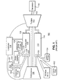
- FIG. 1 is a simplified schematic diagram of an exemplary gas turbine having liquid and gas fuel systems.
- FIG. 1 shows schematically a gas turbine 100 having liquid fuel system 102 and a liquid fuel purge system 104.
- the gas turbine is also capable of running on a gas, such as natural gas, and includes a gaseous fuel system 106.
- Other major components of the gas turbine include a main compressor 108, a combustor 110, a turbine 112 and a controller 114.
- the power output of the gas turbine 112 is a rotating turbine shaft 116, which may be coupled to a generator 130 that produces electric power.
- the combustor may be an annular array of combustion chambers, i.e., cans 118, each of which has a liquid fuel nozzle 120 and a gas fuel nozzle 122 (a single combustor may have one or more gas or liquid fuel nozzle depending on design).
- the combustor may alternatively be an annular chamber. Combustion is initiated within the combustion cans at points slightly downstream of the nozzles. Air from the compressor 108 flows around and through the combustion cans 118 to provide oxygen for combustion. Moreover, water injection nozzles 124 are arranged within the combustor 110 to add energy to the hot combustion gases.
- the air for the liquid fuel system purge may be provided from the compressor 108, boosted by a purge air compressor (not shown) and controlled by other elements of the system (not shown).
- the liquid fuel purge system 104 blows compressed air into the liquid fuel system 102 through the liquid fuel nozzles 120 of the liquid fuel 102 system to purge liquid fuel and provide a flow of continuous cooling air to the liquid fuel nozzles 120.
- the gas fuel purge system 128 blows compressed air into the gas fuel system 106 to purge gas fuel and cool the gas fuel nozzles 122.
- FIG. 2 is a simplified diagram of a gas turbine engine with an existing liquid fuel system.
- Liquid fuel is provided to the liquid fuel system 200 from a liquid fuel source 205.
- the liquid fuel system 200 includes a flowpath to a flow divider 230 through a low-pressure filter 210, a fuel pump 215, a bypass control valve 220, and a stop valve 225.
- Pressure relief valve 235, bypass control valve 220 and stop valve 225 may recirculate liquid fuel flow through recirculation line 240 to the upstream side of the low-pressure filter 210.
- the flow divider 230 divides liquid fuel flow into a plurality of liquid fuel flow paths leading to individual combustion cans 270.
- Each liquid fuel flow path downstream of the flow divider includes a 3-way (endcover) valve 245 and a distribution valve 260 before entering the combustion can 270.
- Three-way valve 245 permits flow to the combustion can nozzles from the liquid fuel flow path (described above) or from a liquid fuel purge air system 280.
- Three-way valve 245 is designed to selectably allow flow to the combustor nozzles 120 from the liquid fuel while preventing backflow of fuel to the liquid fuel purge air system or to allow purge air to the combustor nozzles 120 while preventing backflow of purge air into the liquid fuel system upstream of the three-way valve. By preventing purge air from entering the liquid fuel system, the air-fuel interfaces with the fuel supply are minimized.
- the 3-way valve 245 When gas fuel is supplying the turbine, the 3-way valve 245 is positioned to block liquid fuel flow and allow purge air to pass for cooling the fuel nozzles in the combustor. This purge must be shut off when liquid fuel is turned on.
- the 3-way (endcover) isolation valve separate the purge air from the liquid fuel.
- the fuels system does not require this hardware; the use of 2 check valves, or 2 way on/off valves could be employed.
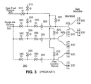
- FIG. 3 illustrates a simplified gas fuel system.
- the gas fuel system 300 includes a gas fuel source 305 and a purge air source 340.
- the gas fuel system further includes a gas stop valve 310, a gas vent valve 315, and gas control valves 320.
- Gas control valves 320 controls the amount of gas fuel admitted to manifolds 325 and the associated gas nozzles 330 downstream of the manifolds 325.
- the purge air source 340 provides compressed air to the combustor gas nozzles to purge the piping and nozzles of gas when the gas fuel and to cool the gas nozzles when the gas fuel is no longer supplying the gas turbine.
- Each line to an individual manifold 325 includes blocking valves 345 and 350 (to satisfy leakage requirements and ensure air and fuel do not mix), vent valve 355, and an orifice 360 for limiting purge air flow.
- the typical gas turbine uses a can annular system where the combustion cans are located at different elevations.
- a mechanical flow divider (connected positive displacement pumps) is used in the liquid fuel system to compensate for this head difference, mostly for the very low flow condition during the startup of the unit.
- a single can within the liquid fuel system may consist of numerous cartridges (nozzles). Due to elevation differences between the cartridges and head effects of the liquid fuel within the can, the highest cartridge will lose liquid fuel flow first.
- FIG. 4 illustrates differences in head driving liquid fuel to flow through liquid fuel nozzles within a combustor can dependent on nozzle positions.
- a side elevation for two simplified combustor cans 410 and 450 are shown, where combustor can 410 is higher than combustor can 450 by height H 1 .
- Combustor can 410 has two nozzles 415 and 420 separated by height H 2 .
- Combustor can 450 has two nozzles 455 and 460 also at different elevations.
- the flow divider 230 ensures an appropriate distribution of liquid fuel flow to each of the individual cans. However, the nozzles within an individual cans are at different elevations. The lower nozzles therefore have a different flows based on the different head based on elevation.
- gas control valve accuracy can vary widely from expected.
- a requested position of 5% stroke might be expected to flow 5% of valve capacity (linear relationship), but instead the valve may be flowing 5% +/- 3% of its capacity.
- This gas fuel flow error results because the gas control valve is not typically calibrated below 10% stroke, as the turbine is not intended to run with valves in these low stroke conditions for any length of time.
- the inaccuracy at low gas control valve strokes will cause incorrect fuel splits to be sent into the combustor and lead to high dynamics within the combustion system. High dynamics are known to increase combustion system wear and decrease part life.
- Controlled fuel is fuel that is provided to the combustors in response to a fuel reference demand for a given power output.
- Uncontrolled fuel is fuel that is introduced to the combustors, but which is not recognized in the turbine control fuel demand signals.
- Liquid fuel prefill is not included in the fuel demand calculation to avoid a detrimental dip in load if the liquid fuel prefill does not reach the combustors as expected, thus creating an under-fueled condition.
- the side effects of the uncontrolled fuel reaching the combustors is to supply additional energy resulting in an initial load and temperature spike and then causing global fuel demand to be driven down over time to hold the same load output.
- Prefill rates may be limited by operational procedures at specific gas turbines, which may be administratively changed. However, high prefill rates may also affect the initial load and temperature spikes described above. Therefore, it may not be possible to implement higher prefill flow rates without incurring penalties in the form or undesirable or unacceptable load and temperature transients.
- FIG. 5 illustrates a prior art algorithm for control of a transfer between fuel types.
- the fuel types are described as fuel “A” and fuel “B”.
- the algorithm provides for a transfer from fuel “A” to fuel “B”.
- step 510 the fuel type to which the load will be transferred is selected and designated and fuel “A”.
- step 520 a fuel prefill is completed with fuel “A”.
- step 530 is determined whether the load is currently being powered by gas fuel, meaning that the load is being switched to liquid fuel (fuel “A” is liquid fuel). If fuel “A” is liquid fuel, then in step 540 a constant first fuel transfer ramp rate is selected. If the load is not being switched to the liquid fuel (but to gas fuel), then in step 550 a constant second fuel transfer rate is selected.
- the first fuel transfer ramp rate may be higher (usually twice as high) than the second fuel transfer ramp rate to recognize that the slow fuel supply is gas and that a transfer to a liquid fuel may be an emergency shift which requires a faster transfer to prevent loss of load.
- step 560 the percent fuel "A” is increased at the fuel transfer ramp rate and the percent fuel “B” is decreased at the fuel transfer ramp rate.
- step 570 a check is performed to determine whether operation with 100% fuel “A” has been achieved. If 100% fuel “A” operation has been achieved, then the transfer is complete in step 580. If 100% operation with fuel “A” has not been achieved then step 560 is continued until full fuel "A” operation has been achieved.
- FIG. 6 illustrates simplified fuel transfer rates for fuel transfers from fuel “A” to fuel “B", and for transfers from fuel “B” to fuel “A” under the prior art method.
- the vertical axis represents the percent of a fuel type that is being supplied during two fuel transfer operations.
- the horizontal axis represents an unscaled time axis showing the relative transfer times during the two fuel transfer operations.
- the solid curve represents fuel type "A”.
- the dashed line represents fuel type "B”.
- the slope ( transfer rate) is twice at high as the slope (transfer rate) from fuel “B” to fuel “A”. Consequently, the transfer time for a fuel transfer from fuel “B” to fuel” A is twice that of the reverse transfer.
- FIG. 6 also illustrates a prefill process for the transfers. Prefilling is performed by supplying the fuel which is to pick up the load earlier than demanded by turbine load control signals in order to ensure that the fuel supply lines for the oncoming fuel source are purged of air and filled with fuel when required to supply turbine load.
- FIG. 7 illustrates high nozzle temperatures resulting from low liquid fuel flow during fuel transfers under the prior art method.
- the left vertical axis indicates values for megawatt output, liquid fuel stroke reference, gas fuel stroke reference and percent liquid fuel.
- the right vertical axis indicates values for nozzle temperatures at various locations around the turbine.
- the percent liquid fuel decreases at a constant ramp rate and the gas fuel stroke reference ramps up reflective of gas fuel flow to the combustor.
- the percent liquid fuel drops below about 10%, nozzle temperatures begin to rise, continuing to increase as percent liquid fuel flow drops to 0%. Nozzle temperature finally drop as a result of liquid fuel purge coming on.
- the present invention relates to a method by which a transfers between offgoing and oncoming sources of fuel for a gas turbine may be controlled to minimize the time spent in adverse operational conditions that may cause damage to gas turbine equipment.
- a method for performing a transfer from an offgoing fuel type to an oncoming fuel type in a gas turbine.
- the method includes completing a fuel prefill for the oncoming fuel type through the fuel system and determining if a total fuel demand for the oncoming fuel type is greater than a predetermined flow rate for the oncoming fuel type.
- the method also includes selecting a fuel transfer rate and transfering from the offgoing fuel type to the oncoming fuel type at the selected fuel transfer rate. Further, the method includes determining if the offgoing fuel flowrate has decreased below a predetermined flow rate for the offgoing fuel type, selecting a final fuel transfer rate and completing the transfer from offgoing fuel type to oncoming fuel type at a selected final fuel transfer rate.
- a method for reducing the effect of uncontrolled liquid fuel from prefilling on gas turbine power transients includes performing a prefill of fuel lines for the oncoming fuel type; and initiating a fast fuel transfer rate for an offgoing fuel type.
- a method for performing a transfer from an offgoing fuel type to an oncoming fuel type in a gas turbine.
- the method includes initally decreasing fuel flowrate from an offgoing fuel type and increasing fuel flowrate from an oncoming fuel type at a fast fuel transfer rate when adverse combustion conditions exist for the combustion system of the oncoming fuel type are avoided and simultaneously when total fuel demand for the oncoming fuel type doe not exceed a fast fuel transfer limit.
- the method includes decreasing fuel flowrate from the offgoing fuel type and increasing fuel flowrate from the oncoming fuel type at a slow fuel transfer rate for the offgoing fuel type when at least one of adverse combustion conditions exist for the combustion system of the offgoing fuel type due to low flowrate no longer exist and total fuel demand for the oncoming exceeds a fast fuel transfer limit. Further, the method includes decreasing fuel flowrate from the offgoing fuel type and increasing flow from the oncoming fuel type at the fast fuel transfer rate when adverse combustion conditions exist for the combustion system of the oncoming fuel type due to low flow and simultaneously when total fuel demand for the oncoming fuel type does not exceed a fast fuel transfer limit.
- the following embodiments of the present invention have many advantages, including providing methods for transfers from liquid fuel to gas fuel and vice versa so the exposure of combustors and nozzles to adverse operational conditions resulting from low liquid fuel flow and low gas fuel flow are minimized.
- the rate of transfer between fuels is no longer a linear function but instead a multiple segment curve that is used to quickly get through problem areas of a fuel transfer.
- Various aspects of the present invention address problem areas of the transfer that can occur at both ends of the fuel transfer and when transferring in either direction or to any fuel.
- Dual fuel gas turbines historically experience problems during gas to liquid fuel transfers.
- This invention corrects one of the major reliability issues, using a purely software based solution.
- This software is applicable to all dual fuel gas turbine engines, and offers increased confidence in gas to liquid fuel transfers and liquid to gas fuel transfers. As a result, improved functionality is provided for both emergency backup transfers and for operation flexibility.
- Increasing reliability of the liquid fuel system (and by extension, customer confidence in it) is an important step in making liquid fuel and hence dual fuel control more viable options.
- One object of the invention is to decrease risk of potential damage or wear on gas turbine hardware during low fuel flow operations seen during fuel transfers, prolonging hardware life.
- a fuel transfer is initiated, two low fuel flow points are seen. The first is the initiation of fuel into the turbine of the fuel being transferred to at the beginning of the transfer; the second is the low fuel flow of the original fuel as it ramps completely off at the end of the transfer.
- the prefill flowrate for the oncoming fuel type is not greater than a fuel flowrate for the oncoming fuel type which will prevent adverse combustion conditions, it is then determined if the prefill flowrate is higher than the maximum allowable limit for the fast fuel transfer rate.
- the maximum allowable limit for fuel demand during the fast fuel transfer ensures rapid fuel transfer rates are turned off in the middle of the fuel transfer to allow time for a successful transition from one fuel to another. Moving too fast while running on mixed fuel in the middle of the transfer could result in loss of flame in one or more of the combustion cans and / or unstable unit operation (output).
- the fast fuel transfer ramp rate is selected and percent fuel demanded of destination fuel is increased until one of the two conditions discussed in the prior paragraph are met.
- the fastest fuel transfer rate must not be faster than either fuel system is capable of meeting to ensure proper control of the turbine is maintained.
- a slow fuel transfer rate is selected and the unit continues to transfer to the oncoming fuel type. The slow rate remains in use until the tail end of the transfer.
- the breakpoints of the fuel transfer curve may be determined by liquid fuel flow rates.
- the liquid fuel flowrate requirements to avoid adverse combustion condition are greater than the minimum gas fuel flowrate requirement. Therefore, using liquid fuel hardware temperatures and corresponding liquid fuel flowrate demands to determine all points of the fuel transfer curve is conservative with respect to minimum gas fuel type flowrates to avoid adverse combustion conditions.
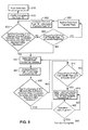
- FIG 8 illustrates an inventive algorithm for control of a transfer between fuel types.
- the fuel types are described as fuel “A” and fuel “B”.
- the algorithm provides for a transfer from fuel “A” to fuel “B” (fuel “A” is the offgoing fuel type and fuel “B” is the oncoming fuel type).
- fuel “A” is the offgoing fuel type and fuel “B” is the oncoming fuel type).
- step 810 the fuel type to which the load will be transferred (oncoming fuel source) is selected and designated as fuel “A”.
- step 820 a fuel prefill is completed with fuel “A”.
- step 840 a slow fuel transfer rate is selected since there is no need to rapidly increase fuel "A" flow.
- step 850 it is determined whether the percent fuel "A" is greater than fast fuel transfer rate limit at the beginning of the transfer.
- the fast fuel transfer limit is the maximum fuel demand for fuel “A” that which a successful fast fuel transfer rate can be carried out. If the percent fuel "A” is above the fast fuel transfer rate limit, then a fast fuel transfer rate should not be selected, but the slow fuel transfer rate should be chosen as in step 840. The limit ensures that rapid fuel transfer rates are turned off in the middle of the fuel transfer to allow time for a successful transition form one fuel to another. Moving too fast while running on mixed fuel in the middle of the transfer could result in loss of flame in one or more of the combustion cans and/ or unstable unit operation (output).
- the fast fuel transfer rate is chosen in step 855. Fuel is transferred from fuel “A” to fuel “B” at the fast fuel transfer rate until it is determined that either the total fuel demand on fuel “A” is above the minimum flow to prevent adverse operational conditions on the combustor nozzles for fuel “A” in step 830 or that the percent fuel “A” is above the fast fuel transfer rate limit.
- step 840 the slow fuel transfer rate is selected and the fuel "A" is increased and fuel “B” is decreased at the slow fuel transfer rate while checking in step 865 to determine if total fuel demand of fuel “B” is less than minimum flow to prevent adverse operational conditions associated with fuel “B” system. If the total fuel demand is step 865 is not below the minimum flow to prevent adverse operational conditions associated with fuel “B” system, then the fuel transfer continues at a the low fuel transfer rate in step 840. If the total fuel demand of fuel “B” is less than the minimum flow to prevent adverse operational conditions, the percent fuel "A” is checked step 840 to determine if it is above the fast fuel transfer rate limit.
- step 875 Fuel transfer continues in step 880 at the fast fuel transfer rate until operation is at 100% fuel "A", when the transfer is complete in step 890.
- FIG. 9 illustrates simplified fuel transfer rates for fuel transfers from fuel “A” to fuel “B” and for transfers from fuel “B” to fuel “A” under an inventive algorithm.
- the vertical axis represents the percent of a fuel type that is being supplied during two fuel transfer operations.
- the horizontal axis represents an unscaled time axis showing the relative transfer times during the two fuel transfer operations.
- the solid curve represents fuel type "A”.
- the dashed line represents fuel type "B”.
- the fast fuel transfer rate from fuel “A” to fuel “B” (the initial slope at the beginning of the transfer and the final slope at the end of the transfer) has the same value as the fast transfer rate at both ends of the transfer from fuel "B" to fuel "A”.
- the slow fuel transfer rate from fuel “A” to fuel “B” is selected to maintain a fixed total transfer time shown as Y (after accounting for the time expended during the fast transfer segments).
- the slow fuel transfer rate from fuel “B” to fuel “A” is selected to maintain a fixed total transfer time shown as 2Y (after accounting for the time expended during the fast transfer segments).
- the breakpoints between the fast fuel transfer rate and the slow fuel transfer rates are fixed at the fast fuel transfer limit. The is twice at high as the slope (transfer rate) from fuel "B” to fuel “A”.
- the total transfer time for a fuel transfer from fuel "B" to fuel” A is twice that of the reverse transfer.
- the transfer In a preferred embodiment of a fuel transfer from an offgoing gas fuel type to an oncoming liquid fuel type, the transfer lasts about 33 seconds. In the transfer from an offgoing liquid fuel to an oncoming gas fuel, the transfer lasts about 66 seconds. Further, in a preferred embodiment for the fuel transfers, the fast transfer ramp rates are set at about 10% fuel load per second for both the offgoing fuel type and the oncoming fuel type. The fast transfer rate of 10% fuel load per second is also preferably employed for both liquid and gas fuel types. The slow ramp rate for the remaining (slow transfer rate) segment of the fuel transfer is determined by calculating the required slow ramp rate to complete the transfer in about 33 seconds for gas fuel to liquid fuel transfers and about 66 seconds for liquid fuel to gas fuel transfers. The slow transfer rates may vary from about 0.9% per second to about 3% per second. Further in a preferred embodiment the fast transfer fuel limit is about 25%.
- Further aspects of the may include dynamics measurements taken within the combustion cans during low gas fuel flows to further optimize breakpoints of the non-linear transfer curve.
- Gas nozzles may also be instrumented in a similar manner to determine the exact fuel split function relation, and rate of fuel transfer could be scheduled as a function of load or other factors to further optimize the non-linear transfer curve. The above described instrumentation may result in a more refined fuel transfer curve across the entire range of fuel splits and load ranges, and in any transfer direction.
- This inventive method is not limited to liquid to gas transfers, but also may include transfers between natural gas fuel to and from Syn-gas systems (dual gas).
- FIGS. 10A and 10B illustrate a comparison of fuel prefill under the prior art and various inventive non-linear fuel transfer methods.
- An additional benefit of the new non-linear transfer is that the total fuel system disturbance due to uncontrolled prefill fuel is lessened.
- Prefill establishes a low initial fixed flow rate for the oncoming fuel source to ensure that the fuel lines are emptied of purge air and filled with oncoming fuel before the fuel is demanded in a signal for load control of the turbine.
- the prefill is established by a positioning a fuel control valve to create the desired prefill flow rate.
- a ramp transfer rate is established for the oncoming fuel source, shown as fuel "A”. While the ramp control transfer rate initially calls for a 0% flow of fuel "A", the position of the control valve is maintained at the prefill position (maintaining the prefill flow) until t 2 when a higher fuel is demanded and the control valve is further opened.
- the shaded area represents the quantity of uncontrolled fuel that is introduced to the combustors above the fuel demanded for turbine control. This uncontrolled fuel causes megawatt power and temperatures for the gas turbine to transiently rise above demanded levels.
- FIG. 10B illustrates a higher ramp rate (slope) for fuel "A”. Due to the higher ramp rate for fuel "A”, the controlled fuel demanded by the turbine control rises quickly from t 3 to above the prefill level, resulting in less uncontrolled fuel reaching the combustors, thereby significantly limiting the disturbance associated with the introduction of uncontrolled fuel.
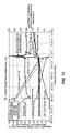
- FIG. 11 illustrates lower fuel nozzle temperatures resulting from non-linear fuel transfer rates during fuel transfers under the inventive method, where the fuel transfer rate is shifted at critical points to quickly pass through undesirable operational modes.
- Field data from testing with a GE 9FA turbine site with the inventive algorithm is displayed.
- the left vertical axis indicates values for megawatt output, liquid fuel stroke reference, gas fuel stroke reference and percent liquid fuel.
- the right vertical axis indicates values for nozzle temperatures at various locations around the turbine.
- liquid fuel nozzle temperatures would exceed 2000 deg F. Over time this high temperature spike could damage the hardware and make liquid fuel operation difficult, as proper atomization of the liquid fuel for burning would not take place. Similar damage to gas fuel nozzle could take place (typically on the diffusion nozzles which are exposed to the flame front).
- liquid fuel nozzle temperature spikes are limited to approximately 300 deg F. Analysis has shown 300 deg F to be well within design parameters and will not result in any hardware damage or increased wear in the long term. Nozzle temperatures subsequently drop due to the initiation of an air purge of the liquid fuel system with its consequent cooling effect on the liquid fuel nozzles.
Landscapes
- Engineering & Computer Science (AREA)
- Chemical & Material Sciences (AREA)
- Combustion & Propulsion (AREA)
- Mechanical Engineering (AREA)
- General Engineering & Computer Science (AREA)
- Engine Equipment That Uses Special Cycles (AREA)
- Feeding And Controlling Fuel (AREA)
Applications Claiming Priority (1)
| Application Number | Priority Date | Filing Date | Title |
|---|---|---|---|
| US11/645,367 US7770400B2 (en) | 2006-12-26 | 2006-12-26 | Non-linear fuel transfers for gas turbines |
Publications (2)
| Publication Number | Publication Date |
|---|---|
| EP1942260A2 true EP1942260A2 (fr) | 2008-07-09 |
| EP1942260A3 EP1942260A3 (fr) | 2013-12-25 |
Family
ID=39203272
Family Applications (1)
| Application Number | Title | Priority Date | Filing Date |
|---|---|---|---|
| EP07123430.6A Withdrawn EP1942260A3 (fr) | 2006-12-26 | 2007-12-18 | Transferts de carburant non linéaires pour turbines à gaz |
Country Status (5)
| Country | Link |
|---|---|
| US (1) | US7770400B2 (fr) |
| EP (1) | EP1942260A3 (fr) |
| JP (1) | JP5113505B2 (fr) |
| KR (1) | KR20080060192A (fr) |
| CN (1) | CN101210519B (fr) |
Cited By (4)
| Publication number | Priority date | Publication date | Assignee | Title |
|---|---|---|---|---|
| ITMI20111576A1 (it) * | 2011-09-02 | 2013-03-03 | Alstom Technology Ltd | Metodo per commutare un dispositivo di combustione |
| WO2015025109A1 (fr) * | 2013-08-20 | 2015-02-26 | Snecma | Procédé et système d'injection de carburant dans une chambre de combustion d'un moteur |
| FR3009844A1 (fr) * | 2013-08-20 | 2015-02-27 | Snecma | Procede et dispositif d'injection de carburant dans une chambre de combustion d'un moteur |
| EP2636953A3 (fr) * | 2012-03-05 | 2017-10-18 | General Electric Company | Procédé de fonctionnement d'une chambre de combustion depuis un combustible liquide à un combustible gazeux |
Families Citing this family (40)
| Publication number | Priority date | Publication date | Assignee | Title |
|---|---|---|---|---|
| US7950216B2 (en) * | 2007-01-30 | 2011-05-31 | Pratt & Whitney Canada Corp. | Gas turbine engine fuel control system |
| US7921651B2 (en) * | 2008-05-05 | 2011-04-12 | General Electric Company | Operation of dual gas turbine fuel system |
| US20090272096A1 (en) * | 2008-05-05 | 2009-11-05 | General Electric Company | Single Manifold Dual Gas Turbine Fuel System |
| JP5455329B2 (ja) | 2008-06-24 | 2014-03-26 | Ntn株式会社 | 円筒ころ軸受 |
| JP5464405B2 (ja) * | 2009-04-24 | 2014-04-09 | 三浦工業株式会社 | バーナ |
| JP5322030B2 (ja) * | 2009-04-24 | 2013-10-23 | 三浦工業株式会社 | バーナ |
| US9671797B2 (en) | 2009-05-08 | 2017-06-06 | Gas Turbine Efficiency Sweden Ab | Optimization of gas turbine combustion systems low load performance on simple cycle and heat recovery steam generator applications |
| US9354618B2 (en) | 2009-05-08 | 2016-05-31 | Gas Turbine Efficiency Sweden Ab | Automated tuning of multiple fuel gas turbine combustion systems |
| US9267443B2 (en) | 2009-05-08 | 2016-02-23 | Gas Turbine Efficiency Sweden Ab | Automated tuning of gas turbine combustion systems |
| US8437941B2 (en) | 2009-05-08 | 2013-05-07 | Gas Turbine Efficiency Sweden Ab | Automated tuning of gas turbine combustion systems |
| EP2299091A1 (fr) * | 2009-09-07 | 2011-03-23 | Alstom Technology Ltd | Procédé de commutation de l' opération d'un brûleur d'une turbine à gaz de combustible liquide à combustible gazeux et vice versa. |
| ES2399309T3 (es) * | 2009-09-07 | 2013-03-27 | Alstom Technology Ltd | Método para cambiar una planta de turbina de gas combustible gaseoso a combustible líquido y viceversa |
| US20110167782A1 (en) * | 2010-01-13 | 2011-07-14 | Scott Arthur Tetzlaff | Systems and apparatus for a fuel control assembly for use in a gas turbine engine |
| US9103285B2 (en) * | 2011-01-03 | 2015-08-11 | General Electric Company | Purge system, system including a purge system, and purge method |
| US20120180873A1 (en) * | 2011-01-14 | 2012-07-19 | General Electric Company | Method for replicating a pressure control valve with adjustable response characteristic |
| US9279370B2 (en) * | 2011-10-28 | 2016-03-08 | General Electric Company | Turbomachine and method of operating a turbomachine to perform a fuel change over at a high load |
| US9650955B2 (en) * | 2011-11-10 | 2017-05-16 | General Electric Company | System for purging gas fuel circuit for a gas turbine engine |
| EP2597372A2 (fr) * | 2011-11-23 | 2013-05-29 | Alstom Technology Ltd | Procédé de fonctionnement d'un dispositif de combustion durant le fonctionnement transitoire |
| US9103284B2 (en) * | 2012-05-31 | 2015-08-11 | General Electric Company | Utilization of fuel gas for purging a dormant fuel gas circuit |
| JP2013253602A (ja) * | 2012-06-06 | 2013-12-19 | General Electric Co <Ge> | 再起動のために発電機を準備するように発電機をシャットダウンするための方法 |
| US9354141B1 (en) * | 2013-06-17 | 2016-05-31 | Jansen's Aircraft Systems Controls, Inc. | Turbine liquid fuel simulator |
| CN104863717B (zh) * | 2015-01-28 | 2018-05-04 | 北京华清燃气轮机与煤气化联合循环工程技术有限公司 | 用于燃气轮机燃料切换的控制方法和系统 |
| US10443510B2 (en) * | 2016-07-14 | 2019-10-15 | General Electric Company | Model based bump-less transfer between passive and active mode operation of three-way check valve for liquid fuel delivery in gas turbine systems |
| US10221774B2 (en) | 2016-07-21 | 2019-03-05 | United Technologies Corporation | Speed control during motoring of a gas turbine engine |
| US10618666B2 (en) | 2016-07-21 | 2020-04-14 | United Technologies Corporation | Pre-start motoring synchronization for multiple engines |
| EP3273006B1 (fr) | 2016-07-21 | 2019-07-03 | United Technologies Corporation | Démarrage en alternance d'un groupe bi-moteur |
| US10384791B2 (en) | 2016-07-21 | 2019-08-20 | United Technologies Corporation | Cross engine coordination during gas turbine engine motoring |
| EP3273016B1 (fr) | 2016-07-21 | 2020-04-01 | United Technologies Corporation | Coordination multimoteur pendant la motorisation de moteur à turbine à gaz |
| US10787968B2 (en) | 2016-09-30 | 2020-09-29 | Raytheon Technologies Corporation | Gas turbine engine motoring with starter air valve manual override |
| US10378447B2 (en) | 2016-09-30 | 2019-08-13 | General Electric Company | System and method for purging fuel or coolant from turbomachine |
| JP6779097B2 (ja) * | 2016-10-24 | 2020-11-04 | 三菱パワー株式会社 | ガスタービン燃焼器及びその運転方法 |
| US10823079B2 (en) * | 2016-11-29 | 2020-11-03 | Raytheon Technologies Corporation | Metered orifice for motoring of a gas turbine engine |
| US11359554B2 (en) * | 2020-03-05 | 2022-06-14 | General Electric Company | System and method for fuel nozzle cleaning during engine operation |
| US11261803B2 (en) * | 2020-03-05 | 2022-03-01 | General Electric Company | Method and system for fuel nozzle cleaning during engine operation |
| CN116802391A (zh) * | 2021-02-15 | 2023-09-22 | 三菱重工业株式会社 | 燃料供给方法、燃料供给设备、具备该燃料供给设备的燃料燃烧设备以及燃气轮机设备 |
| US11760501B2 (en) * | 2021-06-11 | 2023-09-19 | Pratt & Whitney Canada Corp. | Means for handling gaseous fuel |
| CN115750110A (zh) * | 2021-08-26 | 2023-03-07 | 中国航发商用航空发动机有限责任公司 | 发动机的燃油控制方法、装置、电子设备、存储介质 |
| US11946378B2 (en) | 2022-04-13 | 2024-04-02 | General Electric Company | Transient control of a thermal transport bus |
| CN114837823B (zh) * | 2022-04-25 | 2023-10-03 | 中国船舶重工集团公司第七0三研究所 | 一种基于双燃料控制系统的燃气轮机启动逻辑方法 |
| US11927142B2 (en) | 2022-07-25 | 2024-03-12 | General Electric Company | Systems and methods for controlling fuel coke formation |
Family Cites Families (22)
| Publication number | Priority date | Publication date | Assignee | Title |
|---|---|---|---|---|
| US4039804A (en) * | 1972-03-14 | 1977-08-02 | Westinghouse Electric Corporation | System and method for monitoring industrial gas turbine operating parameters and for providing gas turbine power plant control system inputs representative thereof |
| US3948043A (en) * | 1974-08-08 | 1976-04-06 | Westinghouse Electric Corporation | Combined cycle electric power plant and a gas turbine and afterburner having coordinated fuel transfer |
| US3979904A (en) * | 1974-08-08 | 1976-09-14 | Westinghouse Electric Corporation | Combined cycle electric power plant and a gas turbine having improved liquid fuel flow detection |
| US3978659A (en) * | 1975-02-19 | 1976-09-07 | Westinghouse Electric Corporation | Bumpless transfer in shifting control command between the primary and backup control systems of a gas turbine power plant |
| JPS5855332B2 (ja) * | 1978-06-07 | 1983-12-09 | 株式会社日立製作所 | 二燃料焚き圧力噴霧式燃料ノズルのパ−ジ方法及び装置 |
| JPS55128627A (en) * | 1979-03-28 | 1980-10-04 | Hitachi Ltd | Apparatus for determining mixed fuel burning ratio |
| US4442665A (en) * | 1980-10-17 | 1984-04-17 | General Electric Company | Coal gasification power generation plant |
| JPH076416B2 (ja) * | 1986-12-05 | 1995-01-30 | 株式会社日立製作所 | 2種類の燃料を使用するガスタ−ビンの燃料切替装置 |
| JPH07189746A (ja) * | 1993-12-28 | 1995-07-28 | Hitachi Ltd | ガスタービン燃焼器の制御方法 |
| US5617716A (en) * | 1994-09-16 | 1997-04-08 | Electric Power Research Institute | Method for supplying vaporized fuel oil to a gas turbine combustor and system for same |
| JPH08200096A (ja) * | 1995-01-23 | 1996-08-06 | Toshiba Corp | 発電用ガスタービン設備の燃料供給装置 |
| JP3453225B2 (ja) * | 1995-08-28 | 2003-10-06 | 三菱重工業株式会社 | ガスタービンプラントの燃料切替え方法及び切替え装置 |
| JP3901824B2 (ja) * | 1998-02-13 | 2007-04-04 | 三菱重工業株式会社 | ガスタービン予混合燃焼器の燃料切替システム |
| JP4094196B2 (ja) * | 2000-01-07 | 2008-06-04 | 株式会社東芝 | ガスタービン燃料切替制御装置 |
| US6729135B1 (en) * | 2002-12-12 | 2004-05-04 | General Electric Company | Liquid fuel recirculation system and method |
| JP2006161603A (ja) * | 2004-12-03 | 2006-06-22 | Ebara Corp | ガスタービン装置およびガスタービン発電システム |
| JP4568592B2 (ja) * | 2004-12-07 | 2010-10-27 | 三菱重工業株式会社 | 燃料ガス加熱制御装置及びこの燃料ガス加熱制御装置を備えるガスタービン発電施設 |
| US20060150631A1 (en) * | 2005-01-11 | 2006-07-13 | General Electric Company | Liquid fuel recirculation system and method |
| JP2006283714A (ja) * | 2005-04-04 | 2006-10-19 | Honda Motor Co Ltd | ガスタービン・エンジンの制御装置 |
| US7721521B2 (en) * | 2005-11-07 | 2010-05-25 | General Electric Company | Methods and apparatus for a combustion turbine fuel recirculation system and nitrogen purge system |
| US7730711B2 (en) * | 2005-11-07 | 2010-06-08 | General Electric Company | Methods and apparatus for a combustion turbine nitrogen purge system |
| US7950238B2 (en) * | 2006-10-26 | 2011-05-31 | General Electric Company | Method for detecting onset of uncontrolled fuel in a gas turbine combustor |
-
2006
- 2006-12-26 US US11/645,367 patent/US7770400B2/en not_active Expired - Fee Related
-
2007
- 2007-12-13 JP JP2007321456A patent/JP5113505B2/ja not_active Expired - Fee Related
- 2007-12-18 EP EP07123430.6A patent/EP1942260A3/fr not_active Withdrawn
- 2007-12-21 CN CN200710305366XA patent/CN101210519B/zh not_active Expired - Fee Related
- 2007-12-26 KR KR1020070137941A patent/KR20080060192A/ko not_active Ceased
Cited By (8)
| Publication number | Priority date | Publication date | Assignee | Title |
|---|---|---|---|---|
| ITMI20111576A1 (it) * | 2011-09-02 | 2013-03-03 | Alstom Technology Ltd | Metodo per commutare un dispositivo di combustione |
| EP2565427A1 (fr) * | 2011-09-02 | 2013-03-06 | Alstom Technology Ltd | Procédé de commutation d'un dispositif de combustion d'un moteur à turbine à gaz d'une opération avec un premier carburant prémélangé à un deuxième carburant prémélangé |
| RU2539932C2 (ru) * | 2011-09-02 | 2015-01-27 | Альстом Текнолоджи Лтд | Способ переключения подачи топлива в камеру сгорания |
| US9388745B2 (en) | 2011-09-02 | 2016-07-12 | General Electric Technology Gmbh | Method for switching over a combustion device between a first fuel and a second fuel |
| EP2636953A3 (fr) * | 2012-03-05 | 2017-10-18 | General Electric Company | Procédé de fonctionnement d'une chambre de combustion depuis un combustible liquide à un combustible gazeux |
| WO2015025109A1 (fr) * | 2013-08-20 | 2015-02-26 | Snecma | Procédé et système d'injection de carburant dans une chambre de combustion d'un moteur |
| FR3009844A1 (fr) * | 2013-08-20 | 2015-02-27 | Snecma | Procede et dispositif d'injection de carburant dans une chambre de combustion d'un moteur |
| US10072578B2 (en) | 2013-08-20 | 2018-09-11 | Safran Aircraft Engines | Method and system for injecting fuel into an engine combustion chamber |
Also Published As
| Publication number | Publication date |
|---|---|
| KR20080060192A (ko) | 2008-07-01 |
| JP2008163939A (ja) | 2008-07-17 |
| US20080154474A1 (en) | 2008-06-26 |
| CN101210519B (zh) | 2013-05-29 |
| JP5113505B2 (ja) | 2013-01-09 |
| CN101210519A (zh) | 2008-07-02 |
| EP1942260A3 (fr) | 2013-12-25 |
| US7770400B2 (en) | 2010-08-10 |
Similar Documents
| Publication | Publication Date | Title |
|---|---|---|
| US7770400B2 (en) | Non-linear fuel transfers for gas turbines | |
| US7950238B2 (en) | Method for detecting onset of uncontrolled fuel in a gas turbine combustor | |
| US10208678B2 (en) | Gas turbine combustion control device and combustion control method and program therefor | |
| US6655152B2 (en) | Fuel control system for multiple burners | |
| US8355819B2 (en) | Method, apparatus and system for igniting wide range of turbine fuels | |
| US10408131B2 (en) | Combustion staging system | |
| EP2504547B1 (fr) | Procédé de commande de mode en fonction de la température d'échappement pour une turbine à gaz et turbine à gaz | |
| US8356484B2 (en) | Hybrid Wobbe control during rapid response startup | |
| US10982858B2 (en) | Combustion staging system | |
| EP1008737B1 (fr) | Système et méthode d'alimentation en carburant | |
| EP3239610A1 (fr) | Système d'activation de combustion | |
| US11208959B2 (en) | System and method for flexible fuel usage for gas turbines | |
| US20180163636A1 (en) | Fuel supply system | |
| US20200400074A1 (en) | Fuel supply control device | |
| RU2754490C1 (ru) | Способ управления газовой турбиной, контроллер для газовой турбины, газовая турбина и машиночитаемый носитель данных | |
| RU2754621C1 (ru) | Способ управления газовой турбиной, контроллер для газовой турбины, газовая турбина и машиночитаемый носитель данных | |
| JP5566777B2 (ja) | デュアル燃料ガスタービンプラントの燃料切替制御機構、ガスタービンプラント及びデュアル燃料ガスタービンプラントの燃料切替制御方法 | |
| US10221777B2 (en) | Gas turbine combustion control device and combustion control method and program therefor | |
| US11725593B2 (en) | Gas turbine and method for adjusting flow rate of fuel supplied thereto | |
| US20100326077A1 (en) | System for mitigating a fuel system transient | |
| US20100326081A1 (en) | Method for mitigating a fuel system transient | |
| US20260104014A1 (en) | Systems and methods for filling a fuel manifold of a gas turbine engine | |
| RU2773595C2 (ru) | Способ управления подачей топлива в камеру сгорания газотурбинного двигателя, система подачи топлива и газотурбинный двигатель | |
| RU2781460C1 (ru) | Способ управления газотурбинным двигателем с форсажной камерой сгорания | |
| US20180135528A1 (en) | Systems and methods for adaptively prefilling fuel circuits |
Legal Events
| Date | Code | Title | Description |
|---|---|---|---|
| PUAI | Public reference made under article 153(3) epc to a published international application that has entered the european phase |
Free format text: ORIGINAL CODE: 0009012 |
|
| AK | Designated contracting states |
Kind code of ref document: A2 Designated state(s): AT BE BG CH CY CZ DE DK EE ES FI FR GB GR HU IE IS IT LI LT LU LV MC MT NL PL PT RO SE SI SK TR |
|
| AX | Request for extension of the european patent |
Extension state: AL BA HR MK RS |
|
| PUAL | Search report despatched |
Free format text: ORIGINAL CODE: 0009013 |
|
| AK | Designated contracting states |
Kind code of ref document: A3 Designated state(s): AT BE BG CH CY CZ DE DK EE ES FI FR GB GR HU IE IS IT LI LT LU LV MC MT NL PL PT RO SE SI SK TR |
|
| AX | Request for extension of the european patent |
Extension state: AL BA HR MK RS |
|
| RIC1 | Information provided on ipc code assigned before grant |
Ipc: F02C 9/40 20060101AFI20131115BHEP |
|
| AKY | No designation fees paid | ||
| REG | Reference to a national code |
Ref country code: DE Ref legal event code: R108 |
|
| REG | Reference to a national code |
Ref country code: DE Ref legal event code: R108 Effective date: 20140903 |
|
| STAA | Information on the status of an ep patent application or granted ep patent |
Free format text: STATUS: THE APPLICATION IS DEEMED TO BE WITHDRAWN |
|
| 18D | Application deemed to be withdrawn |
Effective date: 20140701 |