EP1942297A2 - Bâtiment doté de nombreux composants en béton - Google Patents
Bâtiment doté de nombreux composants en béton Download PDFInfo
- Publication number
- EP1942297A2 EP1942297A2 EP07023235A EP07023235A EP1942297A2 EP 1942297 A2 EP1942297 A2 EP 1942297A2 EP 07023235 A EP07023235 A EP 07023235A EP 07023235 A EP07023235 A EP 07023235A EP 1942297 A2 EP1942297 A2 EP 1942297A2
- Authority
- EP
- European Patent Office
- Prior art keywords
- projections
- wall
- precast concrete
- building
- walls
- Prior art date
- Legal status (The legal status is an assumption and is not a legal conclusion. Google has not performed a legal analysis and makes no representation as to the accuracy of the status listed.)
- Withdrawn
Links
Images

Classifications
-
- F—MECHANICAL ENGINEERING; LIGHTING; HEATING; WEAPONS; BLASTING
- F16—ENGINEERING ELEMENTS AND UNITS; GENERAL MEASURES FOR PRODUCING AND MAINTAINING EFFECTIVE FUNCTIONING OF MACHINES OR INSTALLATIONS; THERMAL INSULATION IN GENERAL
- F16L—PIPES; JOINTS OR FITTINGS FOR PIPES; SUPPORTS FOR PIPES, CABLES OR PROTECTIVE TUBING; MEANS FOR THERMAL INSULATION IN GENERAL
- F16L13/00—Non-disconnectable pipe joints, e.g. soldered, adhesive, or caulked joints
- F16L13/10—Adhesive or cemented joints
- F16L13/11—Adhesive or cemented joints using materials which fill the space between parts of a joint before hardening
- F16L13/113—Adhesive or cemented joints using materials which fill the space between parts of a joint before hardening for concrete pipes
-
- F—MECHANICAL ENGINEERING; LIGHTING; HEATING; WEAPONS; BLASTING
- F16—ENGINEERING ELEMENTS AND UNITS; GENERAL MEASURES FOR PRODUCING AND MAINTAINING EFFECTIVE FUNCTIONING OF MACHINES OR INSTALLATIONS; THERMAL INSULATION IN GENERAL
- F16L—PIPES; JOINTS OR FITTINGS FOR PIPES; SUPPORTS FOR PIPES, CABLES OR PROTECTIVE TUBING; MEANS FOR THERMAL INSULATION IN GENERAL
- F16L37/00—Couplings of the quick-acting type
- F16L37/08—Couplings of the quick-acting type in which the connection between abutting or axially overlapping ends is maintained by locking members
- F16L37/12—Couplings of the quick-acting type in which the connection between abutting or axially overlapping ends is maintained by locking members using hooks, pawls, or other movable or insertable locking members
- F16L37/14—Joints secured by inserting between mating surfaces an element, e.g. a piece of wire, a pin, a chain
- F16L37/142—Joints secured by inserting between mating surfaces an element, e.g. a piece of wire, a pin, a chain where the securing element is inserted tangentially
- F16L37/148—Joints secured by inserting between mating surfaces an element, e.g. a piece of wire, a pin, a chain where the securing element is inserted tangentially the securing element being flexible
Definitions
- the invention relates to a building, which is composed of several, each comprising a number of walls precast concrete components, each two adjacent precast concrete components are connected to each other via at least two abutting walls.
- prefabricated concrete elements or concrete elements are industrially prefabricated components made of concrete, which are transported in one piece to the site and finally assembled there.
- a reinforcement e.g. made of reinforcing steel.
- reinforced concrete elements or prefabricated components Such characteristics with a concrete insert made of steel or the like shall be expressly included in the following by the term "precast concrete component". Due to the high degree of standardization, which is usually associated with the use of precast concrete components, the corresponding structures can be built relatively quickly and inexpensively.
- connection reinforcement For this purpose, the components to be connected, eg (steel) concrete walls, provided in their connection area with over the concrete base body protruding or protruding, usually metallic reinforcing bars.
- the two components are then aligned and positioned relative to each other for mounting such that their reinforcing brackets are arranged overlapping one another or one behind the other, so that one or more continuous reinforcing rods can be inserted through the bracket.
- connection area is turned on and concreted, whereby a reinforced by the stirrup reinforcement and the continuous reinforcing bars cohesive connection between the precast concrete components arises.
- connection of precast concrete components is comparatively time-consuming and cost-intensive. This is especially true in the on-site assembly of reinforced concrete channels from individual channel segments in a dedicated excavation or in a pit, for example in industrial or power plant construction, with correspondingly tight working and room conditions. Because of the installation work to be carried out, the excavation must often be greater than necessary for the sewer itself. The exact alignment of the components to each other before concreting the connection area is associated with relatively high costs. Moreover, especially in industrial construction and in the nuclear power plant sector, in the assembly of concrete ducts, individual prefabricated duct segments, e.g. for receiving cables or pipelines, particularly high demands on the flexural rigidity of the respective connection point, which can not always be guaranteed with the connection and assembly techniques described above.
- the present invention is therefore based on the object, a building of the type mentioned above, in particular a concrete channel for a power plant to specify that can be assembled very quickly and easily using precast concrete components, the connection between the individual components expediently even when occurring comparatively high pressure or shear forces should be particularly resistant to bending.
- each of the two interconnected walls of the prefabricated components has, on its connection side, a number of projections separated by intermediate spaces, wherein the projections and spaces of one wall are complementary to the projections and spaces of the other wall, so that they mutually engage in the manner of a toothing.
- the invention is based on the over-deflection that should be omitted to simplify the installation and for a shortening of the required installation time in the connection of precast concrete components on the previously customary shuttering and concreting the connection area.
- the individual precast concrete components should already be designed by the contouring of their respective connection area that similar to the known from the wood construction butt joints or Verläept according to the tongue-and-groove principle allows a mutual position and orientation centering bringing together or nesting is, wherein a substantial part of the forces acting on the connection region in later operation or use pressure or shear forces should be absorbed and compensated by the appropriate design of the individual fasteners and the shape and position of their contact surfaces contacting each other.
- an at least partially form-fitting connection between the precast concrete components in which the peripherally mounted on the respective component projections or brackets in the nature of complementary connection partners engage in each other substantially gap-free and thereby form a toothing.
- a mutual displacement of the components is - at least in the expansion direction of the respective "row of teeth" - safely avoided even at relatively high pressure or bending stress, without the need for a cohesive, monolithic connection between the components.
- connection-side projections or brackets are advantageously an integral part of the respective wall and thus of the respective prefabricated component. That is, they are co-molded in its manufacture.
- the required for this, due to the kompiexeren outer contours of the component slightly increased effort for the production of the casing is hardly significant in the industrial mass production of such prefabricated components, as one and the same formwork can be used for several concreting operations.
- the interlocking or mutually interlocked projections of the interconnected precast concrete components each have a bore or recess aligned along a common axis, wherein the axis is aligned substantially perpendicular to the elevation direction of the projections, so that over the entire toothing or at least a substantial part of its lateral extent, a coherent cavity with at least one externally accessible insertion opening is formed.
- a push element securing the connection in particular a steel rod or a steel rod, is then inserted into the cavity thus formed.
- the cavity has a cylindrical shape; the steel or push rod accordingly has a circular cross-section and is suitably matched in diameter to the diameter of the hollow cylinder, that it - apart from a relatively small residual gap - is clamped after insertion substantially free of play in selbigen.
- an intervening gap is filled or pressed with a hardening filling compound, in particular with swellable grout.
- a hardening filling compound in particular with swellable grout.
- all joints or gaps between the interlocking projections are expediently sealed. It is particularly advantageous to press the filling compound with high pressure from the side of the slightly accessible from the outside insertion opening into the example annular gap between the outside of the push rod and the inner surface of the cavity formed by the individual recesses in the projections, so that they still due to pressure is pressed before the onset of hardening by the of the gap "branching" joints between the teeth forming projections and then closes with the onset of hardening.
- the teeth forming projections have a cuboid shape.
- all protrusions of the respective connection side of a wall are preferably arranged on a flat base surface, preferably on an edge surface of the wall, and have the same height above the base surface.
- the width of the individual projections is advantageously substantially the same size, as is the width of the intervening, also cuboidal spaces, so that overall results in a highly standardized and easy to produce "rectangular teeth" or "Quaderveriereung” without undercuts or the like.
- each of the precast concrete components has a top wall and a bottom wall as well as two side walls, which have a longitudinal section form a channel of preferably rectangular cross-section, wherein the precast concrete components are arranged along a longitudinal axis one behind the other and connected to each other. Preference is given to the teeth forming projections and spaces are respectively arranged at the front ends of the two side walls.
- This variant has the advantage that a excavation intended for the concrete channel need not be substantially wider than the channel itself.
- the precast concrete components forming the individual channel segments are e.g. with the aid of a crane in the longitudinal direction in the excavated shaft and placed in the longitudinal direction against each other, so that the respective arranged on the front end regions of the segments projections as intended tooth-like mesh.
- the optionally provided push rods are simply lowered or pushed from above into the vertically oriented cylindrical cavities and then pressed with swellable grout. Side access to the channel elements or segments is not required.
- the advantages achieved by the invention are in particular that by a console-like interlocking connection of precast concrete components from this modular composite structure, especially a concrete channel in power plant construction can be built or assembled in a particularly simple and fast way with low cost, in particular at a backup of the toothing with the help of a through corresponding recesses in the "teeth" inserted push element and subsequent compression of any remaining cavities with mortar a particularly rigid connection can be realized.
- a concrete channel for receiving supply lines of a power plant is composed of a plurality of longitudinally L one behind the other and each interconnected precast concrete components 4, 4 ', of which, however, only two are visible in the section shown here ,
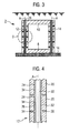
- Each of the prefabricated concrete components 4, 4 ' which are prefabricated industrially in reinforced concrete construction as an integral element thus forms a partial segment of the concrete channel, which here in the exemplary embodiment has a rectangular inner cross section (see also FIG Fig. 3 ), and includes a bottom plate 8 or 8 ', a ceiling plate 10, or 10' and two side walls 12, 14 and 12 ', 14'.
- the bottom plates 8, 8 'of the precast concrete components 4, 4' are aligned horizontally in the assembled final state shown here on a level surface, here a gravel bed 16, on.
- the side walls 12, 14 and 12 ', 14' are therefore vertical, that is aligned perpendicular to the longitudinal direction L.
- the frontal connection areas 18, 18' of the side walls 12, 12 'and 14, 14' and Floor panels 8, 8 'and the decks 10, 10 'of the precast concrete components 4, 4' to be interconnected with respect to their contour coordinated so that when pushing together two resting on the ground, previously separated precast concrete components 4, 4 '- that is, when the concrete at the same level prefabricated components 4, 4 'in the longitudinal direction L are moved towards each other - a toothing of the connection region, in particular between the abutting side walls 12, 12' and 14, 14 ', forms.
- the side wall 12 of the precast concrete component 4 on its right side terminal 18 a plurality, each spaced by gaps 20 from each other parallelepiped projections 22, so that there according to the side view Fig. 1 forms a regular rectangular contour.
- the side wall 12 'of the in Fig. 1 Right arranged precast concrete element 4 ' has on its left terminal side 18' a complementary rectangular contour with gaps 20 'and projections 22', so that the projections 22 of the side wall 4 in the manner of a precisely fitting teeth in the spaces 20 'between the projections 22' the right side wall 4 'intervene and vice versa.
- the extent of the respective base plate 8 or 8 'or ceiling plate 10 or 10' in the longitudinal direction L depends in the embodiment on the corresponding extent of the adjacent side walls 12, 14 and 12 ', 14' of the precast concrete component 4 and 4 'in this Area; It therefore depends on whether the respective "row of teeth" ends there with a "tooth”, ie a projection 22 or 22 ', or with a “tooth gap” (for the sake of simplicity this should also be encompassed by the term “intermediate space”).
- the individual projections 22, 22 'or concrete brackets each have a centrally disposed cylindrical recess 24, so that in the toothed state a continuous from top to bottom through the connection region, along a common vertical axis A aligned cylindrical cavity 26 constant Inner diameter forms.
- this cavity 26 is inserted during the installation of the concrete channel through the top, ie from the ceiling plate 10 'accessible insertion opening 28 as a thrust element 30 effective cylindrical steel rod whose diameter is kept slightly smaller than the diameter of the cylindrical cavity 26.
Landscapes
- Engineering & Computer Science (AREA)
- General Engineering & Computer Science (AREA)
- Mechanical Engineering (AREA)
- Joining Of Building Structures In Genera (AREA)
- Panels For Use In Building Construction (AREA)
Applications Claiming Priority (1)
| Application Number | Priority Date | Filing Date | Title |
|---|---|---|---|
| DE200610058619 DE102006058619A1 (de) | 2006-12-11 | 2006-12-11 | Bauwerk mit einer Mehrzahl von Betonfertigbauteilen |
Publications (2)
| Publication Number | Publication Date |
|---|---|
| EP1942297A2 true EP1942297A2 (fr) | 2008-07-09 |
| EP1942297A3 EP1942297A3 (fr) | 2012-07-04 |
Family
ID=39399521
Family Applications (1)
| Application Number | Title | Priority Date | Filing Date |
|---|---|---|---|
| EP07023235A Withdrawn EP1942297A3 (fr) | 2006-12-11 | 2007-11-30 | Bâtiment doté de nombreux composants en béton |
Country Status (2)
| Country | Link |
|---|---|
| EP (1) | EP1942297A3 (fr) |
| DE (1) | DE102006058619A1 (fr) |
Cited By (1)
| Publication number | Priority date | Publication date | Assignee | Title |
|---|---|---|---|---|
| CN115997063A (zh) * | 2020-08-14 | 2023-04-21 | 李燕芳 | 预制建筑结构件 |
Family Cites Families (9)
| Publication number | Priority date | Publication date | Assignee | Title |
|---|---|---|---|---|
| US1237542A (en) * | 1914-08-01 | 1917-08-21 | John F Morgal | Pavement for roadways. |
| CH83257A (de) * | 1919-03-03 | 1920-04-16 | Hunziker & Cie Zuerich Hartste | Betonbrett zur Bildung von Wänden |
| US1499483A (en) * | 1923-02-13 | 1924-07-01 | James H Simms | Wall construction |
| BE398364A (fr) * | 1932-09-13 | |||
| GB686665A (en) * | 1947-12-15 | 1953-01-28 | Henri Jacques Marc Lambert | Improvements in or relating to methods for assembling two or more elements |
| DE831901C (de) * | 1950-06-29 | 1952-02-18 | Otto Bauer | Baustein fuer verschiedene Zwecke |
| DE2441118A1 (de) * | 1974-08-28 | 1976-03-25 | Buescher Pebueso Beton | Abdichtung an profilbauteilen |
| DE2620027C2 (de) * | 1976-05-06 | 1978-06-29 | Herbert Ing.(Grad.) 4000 Duesseldorf Freudenreich | Kleingebäude für Kinder (Spielhaus) |
| US7134805B2 (en) * | 2004-04-01 | 2006-11-14 | Kwik Slab, Llc | Precast concrete slab system and method therefor |
-
2006
- 2006-12-11 DE DE200610058619 patent/DE102006058619A1/de not_active Withdrawn
-
2007
- 2007-11-30 EP EP07023235A patent/EP1942297A3/fr not_active Withdrawn
Cited By (1)
| Publication number | Priority date | Publication date | Assignee | Title |
|---|---|---|---|---|
| CN115997063A (zh) * | 2020-08-14 | 2023-04-21 | 李燕芳 | 预制建筑结构件 |
Also Published As
| Publication number | Publication date |
|---|---|
| EP1942297A3 (fr) | 2012-07-04 |
| DE102006058619A1 (de) | 2008-06-19 |
Similar Documents
| Publication | Publication Date | Title |
|---|---|---|
| EP2994576A1 (fr) | Bloc, levée de protection contre les inondations et procédé de production correspondant | |
| EP2912238A1 (fr) | Élément paroi pour bâtiment dans la construction de préfabriqués | |
| EP1983111A1 (fr) | Coffrage destiné à limiter les sections de parois moulées, élément de coffrage et procédé de fabrication d'une paroi moulée dans le sol | |
| EP3334869B1 (fr) | Module de bâtiment et bâtiment à plusieurs étages | |
| EP3519641A1 (fr) | Dispositif de liaison servant à relier des éléments préfabriqués à paroi mince et éléments préfabriqués équipés de ce dispositif | |
| EP2792805B1 (fr) | Élément de mur consistant en éléments prèfabriqués | |
| EP1942297A2 (fr) | Bâtiment doté de nombreux composants en béton | |
| DE19920032A1 (de) | Herstellungs- und Montagesystem für Fertigteile von Gebäuden | |
| DE2347007A1 (de) | Kraftschluessige verbindung von vorgefertigten betonbauteilen | |
| AT414247B (de) | Bauwerk | |
| AT503358B1 (de) | Anschlusskorb für vorfabrizierte doppelwandelemente | |
| EP3492665A1 (fr) | Pièce préfabriquée de béton dotée d'au moins un composant recevant la charge ainsi que plaque de raccordement destinée à être agencée dans le joint de raccordement entre une telle pièce préfabriquée de béton et le composant recevant la charge | |
| DE20219324U1 (de) | Gebäudegeschoss | |
| EP1918469B1 (fr) | Système de raccordement d'isolation thermique | |
| DE202015003994U1 (de) | Bauelement, insbesondere zur Errichtung von Pfeilern | |
| DE3876062T2 (de) | Vorgefertigte modularelemente fuer gebaeude. | |
| DE6609772U (de) | Bauteil zur herstellung von schlitz- oder bohrpfahlwaenden. | |
| DE2244886C3 (de) | Mehrgeschossiges Gebäude und Verfahren zu seiner Herstellung | |
| EP1767715A2 (fr) | Mur en paves de verre | |
| DE8816748U1 (de) | Wandtafel mit aus ihr gebildeten Schalungssteinen | |
| DE102016120047A1 (de) | Vorrichtung und Verfahren zur einstückigen Herstellung eines drei Seitenelemente sowie ein Bodenelement und/oder ein Deckenelement aufweisenden Raummoduls | |
| EP3798377B1 (fr) | Procédé de fabrication d'une construction | |
| DE202016105371U1 (de) | Fertigteilmauer | |
| DE202023107453U1 (de) | Vorgefertigter Baublock mit gebrauchsfertiger Wärmedämmung für die Fassade | |
| AT332065B (de) | Verfahren zur herstellung eines deckenartigen stahlbetontragwerkes aus stahlbetonteilen |
Legal Events
| Date | Code | Title | Description |
|---|---|---|---|
| PUAI | Public reference made under article 153(3) epc to a published international application that has entered the european phase |
Free format text: ORIGINAL CODE: 0009012 |
|
| AK | Designated contracting states |
Kind code of ref document: A2 Designated state(s): AT BE BG CH CY CZ DE DK EE ES FI FR GB GR HU IE IS IT LI LT LU LV MC MT NL PL PT RO SE SI SK TR |
|
| AX | Request for extension of the european patent |
Extension state: AL BA HR MK RS |
|
| PUAL | Search report despatched |
Free format text: ORIGINAL CODE: 0009013 |
|
| AK | Designated contracting states |
Kind code of ref document: A3 Designated state(s): AT BE BG CH CY CZ DE DK EE ES FI FR GB GR HU IE IS IT LI LT LU LV MC MT NL PL PT RO SE SI SK TR |
|
| AX | Request for extension of the european patent |
Extension state: AL BA HR MK RS |
|
| RIC1 | Information provided on ipc code assigned before grant |
Ipc: F16L 13/11 20060101AFI20120525BHEP Ipc: F16L 37/14 20060101ALI20120525BHEP |
|
| AKY | No designation fees paid | ||
| REG | Reference to a national code |
Ref country code: DE Ref legal event code: R108 |
|
| REG | Reference to a national code |
Ref country code: DE Ref legal event code: R108 Effective date: 20130313 |
|
| STAA | Information on the status of an ep patent application or granted ep patent |
Free format text: STATUS: THE APPLICATION IS DEEMED TO BE WITHDRAWN |
|
| 18D | Application deemed to be withdrawn |
Effective date: 20130105 |