EP1943407B1 - Tete posterieure et ensemble de forage muni d'une tete posterieure - Google Patents
Tete posterieure et ensemble de forage muni d'une tete posterieure Download PDFInfo
- Publication number
- EP1943407B1 EP1943407B1 EP06827334.1A EP06827334A EP1943407B1 EP 1943407 B1 EP1943407 B1 EP 1943407B1 EP 06827334 A EP06827334 A EP 06827334A EP 1943407 B1 EP1943407 B1 EP 1943407B1
- Authority
- EP
- European Patent Office
- Prior art keywords
- piston
- backhead
- drill assembly
- wear sleeve
- area
- Prior art date
- Legal status (The legal status is an assumption and is not a legal conclusion. Google has not performed a legal analysis and makes no representation as to the accuracy of the status listed.)
- Active
Links
Images





Classifications
-
- E—FIXED CONSTRUCTIONS
- E21—EARTH OR ROCK DRILLING; MINING
- E21B—EARTH OR ROCK DRILLING; OBTAINING OIL, GAS, WATER, SOLUBLE OR MELTABLE MATERIALS OR A SLURRY OF MINERALS FROM WELLS
- E21B4/00—Drives for drilling, used in the borehole
- E21B4/06—Down-hole impacting means, e.g. hammers
- E21B4/14—Fluid operated hammers
-
- E—FIXED CONSTRUCTIONS
- E21—EARTH OR ROCK DRILLING; MINING
- E21B—EARTH OR ROCK DRILLING; OBTAINING OIL, GAS, WATER, SOLUBLE OR MELTABLE MATERIALS OR A SLURRY OF MINERALS FROM WELLS
- E21B10/00—Drill bits
Definitions
- US 5,685,380 discloses another portion of a drill assembly, where a piston is slidably movable within a cylinder that is separate from the backhead.
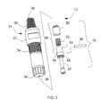
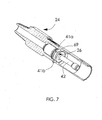
- the securing member can comprise a laterally extending pin inserted through at least one opening in the backhead.
- the securing member can comprise at least two laterally extending pins, each of the pins being inserted through one of a corresponding number of spaced-apart openings in the backhead.
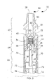
- the backhead assembly 12 includes a backhead 24 and a distributor or check valve assembly 26.
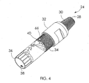
- the backhead 24 is an elongate member having an exposed proximal end 28 with a connection 30 for attachment to a source of pressurized fluid.
- the backhead 24 also has a tool receiving portion 32 shaped to receive a tool, e.g., a wrench, to assist in installing and removing the backhead. Adjacent the tool receiving portion 32 is a threaded portion 34. In the illustrated embodiment, an outer diameter of the backhead is stepped down at a shoulder 33 immediately adjacent the threaded portion 34.
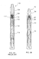
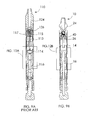
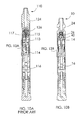
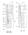
- Fig. 8A and Fig. 8B are section views in elevation showing the conventional drilling tool and a drilling tool according to an embodiment of this application, respectively, in the impact position, i.e., when the piston has contacted the bit, which in turn exerts an impact on any material with which the bit is in contact.
- Figs. 9A and 9B are similar to Figs. 8A and 8B , but shown the respective drilling tools in a drop open position, when the tools have been brought to rest, such as, e.g., if a void is encountered while drilling.
- Figs. 10A and 10B are similar to Figs. 8A and 8B , but show the respective drilling tools in a position when the piston is at the top of its stroke, i.e., withdrawn in the distal direction.
- the flow path 80 is substantially free of sharp bends, loss of energy due to friction and decreases in velocity are reduced. Stated differently, the flow path 80 is much more energy efficient than the flow path 180 in the conventional drilling tool 110. In addition, the flow path 80 does not force the intake flow through any apertures or other bounded openings at sharp angles to the flow's primary direction. Also, the intake flow passes along walls (e.g., the outer periphery of the backhead 24) rather than through them (compare the conventional drilling tool 110, where the intake flow must pass through the inner cylinder 113).
Landscapes
- Engineering & Computer Science (AREA)
- Life Sciences & Earth Sciences (AREA)
- Geology (AREA)
- Mining & Mineral Resources (AREA)
- Mechanical Engineering (AREA)
- Physics & Mathematics (AREA)
- Environmental & Geological Engineering (AREA)
- Fluid Mechanics (AREA)
- General Life Sciences & Earth Sciences (AREA)
- Geochemistry & Mineralogy (AREA)
- Earth Drilling (AREA)
Claims (15)
- Portion d'un ensemble de forage actionnée par une alimentation en fluide comprimé, comprenant :une tête postérieure (24) ayant une extrémité proximale (28) pouvant être reliée à l'alimentation, un alésage axial (38) et une extrémité distale ouverte (36), la tête postérieure (24) ayant des passages (68) s'étendant entre l'alésage axial (38) et la surface extérieure de la tête postérieure (24) ;un manchon d'usure allongé creux (14) ayant une extrémité proximale à laquelle la tête postérieure (24) est accouplée et dans laquelle l'extrémité distale (36) de la tête postérieure (24) est reçue ; etun piston (16) logé dans le manchon d'usure (14) et ayant une extrémité proximale (44), le piston (16) étant mobile de manière coulissante le long du manchon d'usure (14) en réponse à l'acheminement du fluide comprimé à travers la tête postérieure (24),un chemin de flux d'admission (80, 92) pour un flux d'admission de fluide comprimé dans l'outil de forage s'étendant dans une direction distale à partir de l'alésage axial (38), à travers les passages (68) dans la tête postérieure (24), à travers un espace (70) entre la tête postérieure (24) et le manchon d'usure (14) et dans une zone (96) entre le piston (16) et le manchon d'usure (14) et en contact avec le piston (16),caractérisée en ce qu'une portion de cylindre intégrée (65) est définie dans l'extrémité distale (36) de la tête postérieure (24), l'extrémité proximale (44) du piston (16) étant façonnée pour s'insérer à l'intérieur de la portion de cylindre intégrée (65) de la tête postérieure (24), et étant mobile de manière coulissante le long de la portion de cylindre intégrée (65) en réponse au fluide comprimé.
- Portion d'un ensemble de forage selon la revendication 1, dans laquelle le chemin de flux d'admission (80, 92) ne s'étend à travers aucune ouverture forçant le flux d'admission dans une direction radialement vers l'intérieur.
- Portion d'un ensemble de forage selon la revendication 1, dans laquelle le chemin de flux d'admission (80, 92) ne nécessite pas le passage du flux d'admission vers l'intérieur à travers une quelconque ouverture définie dans une paroi latérale de la tête postérieure (24).
- Portion d'un ensemble de forage selon la revendication 1, comprenant en outre un distributeur (26) positionné au moins partiellement à l'intérieur de l'alésage axial (38) entre l'extrémité proximale (28) et l'extrémité distale (36), le distributeur (26) étant fixé de manière amovible à la tête postérieure (24) au moyen d'un organe de fixation (40 ; 41) accessible à partir d'une surface extérieure de la tête postérieure (24), le distributeur (26) comportant une soupape anti-retour (48) qui est ouverte pour permettre le flux d'admission à partir de l'alimentation.
- Portion d'un ensemble de forage selon la revendication 1, comprenant en outre un mandrin (18) accouplé à une extrémité distale du manchon d'usure (14) et susceptible de recevoir un outil de forage (20) et mobile en réponse au contact avec le piston (16).
- Portion d'un ensemble de forage selon la revendication 4, dans laquelle l'organe de fixation comprend une broche (40) s'étendant latéralement insérée à travers au moins une ouverture (66) dans la tête postérieure (24).
- Portion d'un ensemble de forage selon la revendication 4, dans laquelle l'organe de fixation comprend au moins deux broches (41) s'étendant latéralement, chacune des broches (41) étant insérée à travers l'une parmi un nombre correspondant d'ouvertures (67) espacées les unes des autres dans la tête postérieure (24).
- Portion d'un ensemble de forage selon la revendication 4, dans laquelle le distributeur (26) comprend en outre un organe d'étanchéité (50) de soupape anti-retour, un organe de sollicitation (52) qui sollicite l'organe d'étanchéité (50) jusqu'à une position fermée et une portion de guidage (42) s'étendant de manière distale.
- Portion d'un ensemble de forage selon la revendication 1, dans laquelle, lorsque l'ensemble de forage est dans une position de chute ouverte, une extrémité proximale (44) du piston (16) est espacée de la portion de cylindre intégrée (65) dans la direction distale et un espace annulaire ouvert (96) est défini entre une extrémité proximale (44) du piston (16) et le manchon d'usure (14).
- Portion de l'ensemble de forage selon la revendication 9, dans laquelle le piston (16) a une zone de piston disponible (An) soumise à une pression ayant tendance à déplacer le piston (16) dans une direction distale qui est d'environ 5 % à environ 25 % supérieure à la zone de piston disponible (Ac) d'un ensemble de forage traditionnel de même diamètre extérieur.
- Portion de l'ensemble de forage selon la revendication 10, dans laquelle le piston a une zone de piston disponible (An) soumise à une pression ayant tendance à déplacer le piston (16) dans une direction distale qui est d'environ 8 % à environ 10 % supérieure à la zone de piston disponible (Ac) d'un ensemble de forage traditionnel de même diamètre extérieur.
- Portion de l'ensemble de forage selon la revendication 10, dans laquelle le piston (16) a une zone de piston disponible (An) soumise à une pression ayant tendance à déplacer le piston (16) dans une direction distale qui est d'environ 9 % supérieure à la zone de piston disponible (Ac) d'un ensemble de forage traditionnel de même diamètre extérieur.
- Portion d'un ensemble de forage selon la revendication 1, dans laquelle, lorsque l'ensemble de forage est dans une position de chute ouverte, une extrémité proximale (44) du piston (16) est espacée de la portion de cylindre (65) et du manchon d'usure (14).
- Portion d'un ensemble de forage selon la revendication 1, dans laquelle un chemin de flux de remplissage (200) s'étend dans la direction proximale à partir de la zone (96) entre le piston (16) et le manchon d'usure (14), le long du piston (16) et entre le piston (16) et la tête postérieure (24) dans un espace proximal à l'extrémité proximale (44) du piston (16), et dans laquelle une séparation est maintenue entre le chemin de flux d'admission (92) et le chemin de flux de remplissage (200) dans la zone entre le piston (16) et le manchon d'usure (14).
- Portion de l'ensemble de forage selon la revendication 14, dans laquelle l'extrémité distale (36) de la tête postérieure (24) a une paroi circonférentielle configurée pour guider le flux de remplissage (200) s'écoulant dans la direction proximale le long d'une surface intérieure de la paroi et configurée pour guider le flux d'admission (80, 92) s'écoulant dans la direction distale le long d'une surface extérieure de la paroi, le flux d'admission (80, 92) et le flux de remplissage (200) étant séparés l'un de l'autre par la paroi.
Applications Claiming Priority (2)
| Application Number | Priority Date | Filing Date | Title |
|---|---|---|---|
| US73386005P | 2005-11-03 | 2005-11-03 | |
| PCT/US2006/042740 WO2007056035A1 (fr) | 2005-11-03 | 2006-10-31 | Tete posterieure et ensemble de forage muni d’une tete posterieure |
Publications (3)
| Publication Number | Publication Date |
|---|---|
| EP1943407A1 EP1943407A1 (fr) | 2008-07-16 |
| EP1943407A4 EP1943407A4 (fr) | 2012-01-04 |
| EP1943407B1 true EP1943407B1 (fr) | 2015-04-15 |
Family
ID=38023578
Family Applications (1)
| Application Number | Title | Priority Date | Filing Date |
|---|---|---|---|
| EP06827334.1A Active EP1943407B1 (fr) | 2005-11-03 | 2006-10-31 | Tete posterieure et ensemble de forage muni d'une tete posterieure |
Country Status (7)
| Country | Link |
|---|---|
| US (2) | US7617889B2 (fr) |
| EP (1) | EP1943407B1 (fr) |
| KR (1) | KR101011433B1 (fr) |
| AU (1) | AU2006311987B2 (fr) |
| CA (1) | CA2627488C (fr) |
| ES (1) | ES2536070T3 (fr) |
| WO (1) | WO2007056035A1 (fr) |
Families Citing this family (15)
| Publication number | Priority date | Publication date | Assignee | Title |
|---|---|---|---|---|
| US7617889B2 (en) * | 2005-11-03 | 2009-11-17 | Rockmore International, Inc. | Backhead and drill assembly with backhead |
| US8596398B2 (en) | 2007-05-16 | 2013-12-03 | Polaris Industries Inc. | All terrain vehicle |
| SK932007A3 (sk) * | 2007-07-09 | 2009-02-05 | Konek, S. R. O. | Hydraulické rozrušovacie kladivo |
| AU2008345759B2 (en) * | 2008-01-07 | 2012-06-07 | Suk Shin In | Vibration hammer |
| US8302707B2 (en) * | 2009-01-28 | 2012-11-06 | Center Rock Inc. | Down-the-hole drill reverse exhaust system |
| SE539153C2 (sv) * | 2008-03-31 | 2017-04-18 | Center Rock Inc | Drivkoppling för sänkborr |
| US8800690B2 (en) * | 2008-03-31 | 2014-08-12 | Center Rock Inc. | Down-the-hole drill hammer having a reverse exhaust system and segmented chuck assembly |
| USD656974S1 (en) | 2009-01-28 | 2012-04-03 | Center Rock Inc. | Drill bit |
| US8622152B2 (en) | 2009-01-28 | 2014-01-07 | Center Rock Inc. | Down-the-hole drill hammer having a sliding exhaust check valve |
| DE102009023910A1 (de) * | 2009-03-03 | 2010-09-16 | Tracto-Technik Gmbh & Co. Kg | Erdbohrvorrichtung |
| US9016403B2 (en) * | 2012-09-14 | 2015-04-28 | Drillco Tools S.A. | Pressurized fluid flow system having multiple work chambers for a down-the-hole drill hammer and normal and reverse circulation hammers thereof |
| US10100578B2 (en) * | 2013-06-10 | 2018-10-16 | Center Rock, Inc. | Pressure control check valve for a down-the-hole drill hammer |
| RU2549649C1 (ru) * | 2014-03-12 | 2015-04-27 | Федеральное государственное бюджетное учреждение науки Институт горного дела им. Н.А. Чинакала Сибирского отделения Российской академии наук | Погружной пневмоударник |
| CL2017001018A1 (es) * | 2017-04-25 | 2017-12-15 | Drillco Tools S A | Ensamble de culata en martillo de fondo |
| CN111411899B (zh) * | 2020-05-28 | 2023-05-26 | 西南石油大学 | 一种具有自冲击能力的pdc钻头 |
Family Cites Families (36)
| Publication number | Priority date | Publication date | Assignee | Title |
|---|---|---|---|---|
| US3704756A (en) * | 1971-07-19 | 1972-12-05 | Boyles Ind Ltd | Apparatus for lowering and retrieving a core barrel |
| DE2750603A1 (de) * | 1977-11-14 | 1979-05-17 | Inst Gornogo Dela Sibirskogo O | Schlagwerk |
| EP0040026A1 (fr) * | 1980-05-09 | 1981-11-18 | Halifax Tool Company Limited | Machine à piston libre |
| ZA863192B (en) * | 1986-04-29 | 1986-12-30 | Abraham Gien | Improvement in valveless pneumatic hammer |
| AU542647B2 (en) | 1981-01-22 | 1985-02-28 | Dresser Industries Inc. | Percussive down the hole drill |
| US4819739A (en) * | 1984-08-31 | 1989-04-11 | Dresser Industries, Inc. | Fluid actuated rock drill hammer |
| US4828048A (en) * | 1986-11-10 | 1989-05-09 | Mayer James R | Hydraulic Percussion tool |
| US4819746A (en) * | 1987-01-13 | 1989-04-11 | Minroc Technical Promotions Ltd. | Reverse circulation down-the-hole hammer drill and bit therefor |
| US4878550A (en) * | 1988-07-15 | 1989-11-07 | Sandvik Rock Tools, Inc. | Pilot-valve-controlled percussion drilling tool |
| US4923018A (en) * | 1989-03-02 | 1990-05-08 | Sandvik Rock Tools, Inc. | Percussion drill |
| US5325926A (en) * | 1993-02-05 | 1994-07-05 | Ingersoll-Rand Company | Reversible casing for a down-the-hole percussive apparatus |
| US5301761A (en) * | 1993-03-09 | 1994-04-12 | Ingersoll-Rand Company | Pressure reversing valve for a fluid-actuated, percussive drilling apparatus |
| US5685380A (en) * | 1995-01-06 | 1997-11-11 | Minroc Technical Promotions Limited | Reverse circulation down-the-hole drill |
| IE80718B1 (en) | 1995-01-06 | 1998-12-30 | Minroc Techn Promotions Ltd | A reverse circulation down-the-hole drill |
| US5511628A (en) * | 1995-01-20 | 1996-04-30 | Holte; Ardis L. | Pneumatic drill with central evacuation outlet |
| RU2090730C1 (ru) | 1995-05-11 | 1997-09-20 | Институт горного дела СО РАН | Погружной пневматический ударный механизм |
| US5566771A (en) * | 1995-08-30 | 1996-10-22 | Ingersoll-Rand Company | Reversible casing for a self-lubricating, fluid-actuated, percussive down-the-hole drill |
| US5562170A (en) * | 1995-08-30 | 1996-10-08 | Ingersoll-Rand Company | Self-lubricating, fluid-actuated, percussive down-the-hole drill |
| US5682957A (en) | 1995-12-21 | 1997-11-04 | Ingersoll-Rand Company | Water separator for a down hole drill |
| US5803187A (en) * | 1996-08-23 | 1998-09-08 | Javins; Brooks H. | Rotary-percussion drill apparatus and method |
| US5944117A (en) * | 1997-05-07 | 1999-08-31 | Eastern Driller's Manufacturing Co., Inc. | Fluid actuated impact tool |
| WO1999064711A2 (fr) * | 1998-06-12 | 1999-12-16 | Ingersoll-Rand Company | Tete posterieure et clapet de retenue ameliores pour marteaux fond de trou |
| US6062322A (en) * | 1998-06-15 | 2000-05-16 | Sandvik Ab | Precussive down-the-hole rock drilling hammer |
| IES81005B2 (en) * | 1998-11-27 | 1999-09-08 | Minroc Technical Promotions Li | Segmented ring mounting for a fluid-operated percussion drill tool |
| CA2366115A1 (fr) | 1999-03-03 | 2000-09-21 | Earth Tool Company, L.L.C. | Procede et appareil de forage dirige |
| IES20000221A2 (en) | 2000-03-22 | 2001-10-03 | Minroc Techn Promotions Ltd | Down-the-hole hammer with variable pressure chamber |
| AUPQ717100A0 (en) | 2000-04-28 | 2000-05-18 | Rear, Ian Graeme | Down hole hammer having a top sub |
| US6454026B1 (en) * | 2000-09-08 | 2002-09-24 | Sandvik Ab | Percussive down-the-hole hammer for rock drilling, a top sub used therein and a method for adjusting air pressure |
| US6502650B1 (en) * | 2000-11-15 | 2003-01-07 | Sandvik Ab | Percussive down-the-hole hammer for rock drilling, and a drill bit used therein |
| US20040245021A1 (en) * | 2001-10-10 | 2004-12-09 | Taylor Reginald Frederick | Down-the-hole drill hammer |
| AU2002356955B2 (en) * | 2001-11-14 | 2008-07-17 | Atlas Copco Secoroc Llc | Fluid distributor device for down-hole-drills |
| IES20020794A2 (en) | 2002-10-04 | 2003-02-19 | Minroc Techn Promotions Ltd | A down-the-hole hammer |
| US7198120B2 (en) * | 2003-03-25 | 2007-04-03 | Bernard Lionel Gien | Down-the-hole drill assembly |
| US6799641B1 (en) * | 2003-06-20 | 2004-10-05 | Atlas Copco Ab | Percussive drill with adjustable flow control |
| IES20050495A2 (en) * | 2005-07-20 | 2006-11-01 | Minroc Techn Promotions Ltd | A drill bit assembly for fluid-operated percussion drill tools |
| US7617889B2 (en) * | 2005-11-03 | 2009-11-17 | Rockmore International, Inc. | Backhead and drill assembly with backhead |
-
2006
- 2006-10-31 US US11/817,292 patent/US7617889B2/en active Active
- 2006-10-31 CA CA2627488A patent/CA2627488C/fr active Active
- 2006-10-31 KR KR1020087013202A patent/KR101011433B1/ko active Active
- 2006-10-31 AU AU2006311987A patent/AU2006311987B2/en active Active
- 2006-10-31 WO PCT/US2006/042740 patent/WO2007056035A1/fr not_active Ceased
- 2006-10-31 ES ES06827334.1T patent/ES2536070T3/es active Active
- 2006-10-31 EP EP06827334.1A patent/EP1943407B1/fr active Active
-
2009
- 2009-06-29 US US12/494,126 patent/US8006784B2/en active Active
Also Published As
| Publication number | Publication date |
|---|---|
| ES2536070T3 (es) | 2015-05-20 |
| EP1943407A1 (fr) | 2008-07-16 |
| EP1943407A4 (fr) | 2012-01-04 |
| CA2627488A1 (fr) | 2007-05-18 |
| US20090260889A1 (en) | 2009-10-22 |
| US8006784B2 (en) | 2011-08-30 |
| WO2007056035A1 (fr) | 2007-05-18 |
| AU2006311987A1 (en) | 2007-05-18 |
| KR101011433B1 (ko) | 2011-01-28 |
| CA2627488C (fr) | 2012-10-23 |
| US20080156540A1 (en) | 2008-07-03 |
| US7617889B2 (en) | 2009-11-17 |
| KR20080088586A (ko) | 2008-10-02 |
| AU2006311987B2 (en) | 2011-03-10 |
Similar Documents
| Publication | Publication Date | Title |
|---|---|---|
| US8006784B2 (en) | Backhead and drill assembly with backhead | |
| EP2627850B1 (fr) | Marteau de fond de trou | |
| CA2654461C (fr) | Dispositif d'acheminement de matieres solides et de liquides a l'interieur d'un trepan a circulation inverse | |
| KR101412907B1 (ko) | 타격식 해머드릴 | |
| US8973681B2 (en) | Pressurized fluid flow system for a reverse circulation down-the-hole hammer and hammer thereof | |
| US10316586B1 (en) | Pressurized fluid flow system for a DTH hammer and normal circulation hammer thereof | |
| EP3553270B1 (fr) | Système d'écoulement de fluide sous pression pour marteau dth et marteau à circulation normale comprenant ledit système | |
| CN208106309U (zh) | 用于潜孔装置的流体流动控制系统和潜孔锤 | |
| US6550554B2 (en) | Rock drill | |
| US20080078584A1 (en) | Bit assembly for down-hole drills | |
| US11933143B1 (en) | Pressurized fluid flow system for percussive mechanisms | |
| RU2280748C1 (ru) | Компоновка низа бурильной колонны для бурения наклонно направленных и горизонтальных скважин винтовым забойным двигателем | |
| AU2013206483B2 (en) | Pressurized fluid flow system for a reverse circulation down-the-hole hammer and hammer thereof | |
| CN115362307A (zh) | 用于冲击钻工具的冲洗和连接构造 | |
| IES85798Y1 (en) | A down-the-hole hammer | |
| IE20100666U1 (en) | A down-the-hole hammer |
Legal Events
| Date | Code | Title | Description |
|---|---|---|---|
| PUAI | Public reference made under article 153(3) epc to a published international application that has entered the european phase |
Free format text: ORIGINAL CODE: 0009012 |
|
| 17P | Request for examination filed |
Effective date: 20080419 |
|
| AK | Designated contracting states |
Kind code of ref document: A1 Designated state(s): AT BE BG CH CY CZ DE DK EE ES FI FR GB GR HU IE IS IT LI LT LU LV MC NL PL PT RO SE SI SK TR |
|
| A4 | Supplementary search report drawn up and despatched |
Effective date: 20111201 |
|
| RIC1 | Information provided on ipc code assigned before grant |
Ipc: E21B 4/14 20060101AFI20111125BHEP Ipc: E21B 1/38 20060101ALI20111125BHEP |
|
| DAX | Request for extension of the european patent (deleted) | ||
| GRAP | Despatch of communication of intention to grant a patent |
Free format text: ORIGINAL CODE: EPIDOSNIGR1 |
|
| INTG | Intention to grant announced |
Effective date: 20141024 |
|
| GRAS | Grant fee paid |
Free format text: ORIGINAL CODE: EPIDOSNIGR3 |
|
| GRAA | (expected) grant |
Free format text: ORIGINAL CODE: 0009210 |
|
| AK | Designated contracting states |
Kind code of ref document: B1 Designated state(s): AT BE BG CH CY CZ DE DK EE ES FI FR GB GR HU IE IS IT LI LT LU LV MC NL PL PT RO SE SI SK TR |
|
| REG | Reference to a national code |
Ref country code: GB Ref legal event code: FG4D Ref country code: CH Ref legal event code: EP |
|
| REG | Reference to a national code |
Ref country code: IE Ref legal event code: FG4D |
|
| REG | Reference to a national code |
Ref country code: AT Ref legal event code: REF Ref document number: 722105 Country of ref document: AT Kind code of ref document: T Effective date: 20150515 |
|
| REG | Reference to a national code |
Ref country code: ES Ref legal event code: FG2A Ref document number: 2536070 Country of ref document: ES Kind code of ref document: T3 Effective date: 20150520 |
|
| REG | Reference to a national code |
Ref country code: DE Ref legal event code: R096 Ref document number: 602006045163 Country of ref document: DE Effective date: 20150528 |
|
| REG | Reference to a national code |
Ref country code: SE Ref legal event code: TRGR |
|
| REG | Reference to a national code |
Ref country code: NL Ref legal event code: VDEP Effective date: 20150415 |
|
| REG | Reference to a national code |
Ref country code: LT Ref legal event code: MG4D |
|
| PG25 | Lapsed in a contracting state [announced via postgrant information from national office to epo] |
Ref country code: NL Free format text: LAPSE BECAUSE OF FAILURE TO SUBMIT A TRANSLATION OF THE DESCRIPTION OR TO PAY THE FEE WITHIN THE PRESCRIBED TIME-LIMIT Effective date: 20150415 |
|
| PG25 | Lapsed in a contracting state [announced via postgrant information from national office to epo] |
Ref country code: PT Free format text: LAPSE BECAUSE OF FAILURE TO SUBMIT A TRANSLATION OF THE DESCRIPTION OR TO PAY THE FEE WITHIN THE PRESCRIBED TIME-LIMIT Effective date: 20150817 Ref country code: LT Free format text: LAPSE BECAUSE OF FAILURE TO SUBMIT A TRANSLATION OF THE DESCRIPTION OR TO PAY THE FEE WITHIN THE PRESCRIBED TIME-LIMIT Effective date: 20150415 |
|
| PG25 | Lapsed in a contracting state [announced via postgrant information from national office to epo] |
Ref country code: GR Free format text: LAPSE BECAUSE OF FAILURE TO SUBMIT A TRANSLATION OF THE DESCRIPTION OR TO PAY THE FEE WITHIN THE PRESCRIBED TIME-LIMIT Effective date: 20150716 Ref country code: LV Free format text: LAPSE BECAUSE OF FAILURE TO SUBMIT A TRANSLATION OF THE DESCRIPTION OR TO PAY THE FEE WITHIN THE PRESCRIBED TIME-LIMIT Effective date: 20150415 Ref country code: IS Free format text: LAPSE BECAUSE OF FAILURE TO SUBMIT A TRANSLATION OF THE DESCRIPTION OR TO PAY THE FEE WITHIN THE PRESCRIBED TIME-LIMIT Effective date: 20150815 |
|
| REG | Reference to a national code |
Ref country code: DE Ref legal event code: R097 Ref document number: 602006045163 Country of ref document: DE |
|
| PG25 | Lapsed in a contracting state [announced via postgrant information from national office to epo] |
Ref country code: DK Free format text: LAPSE BECAUSE OF FAILURE TO SUBMIT A TRANSLATION OF THE DESCRIPTION OR TO PAY THE FEE WITHIN THE PRESCRIBED TIME-LIMIT Effective date: 20150415 Ref country code: EE Free format text: LAPSE BECAUSE OF FAILURE TO SUBMIT A TRANSLATION OF THE DESCRIPTION OR TO PAY THE FEE WITHIN THE PRESCRIBED TIME-LIMIT Effective date: 20150415 |
|
| PLBE | No opposition filed within time limit |
Free format text: ORIGINAL CODE: 0009261 |
|
| STAA | Information on the status of an ep patent application or granted ep patent |
Free format text: STATUS: NO OPPOSITION FILED WITHIN TIME LIMIT |
|
| PG25 | Lapsed in a contracting state [announced via postgrant information from national office to epo] |
Ref country code: PL Free format text: LAPSE BECAUSE OF FAILURE TO SUBMIT A TRANSLATION OF THE DESCRIPTION OR TO PAY THE FEE WITHIN THE PRESCRIBED TIME-LIMIT Effective date: 20150415 Ref country code: RO Free format text: LAPSE BECAUSE OF NON-PAYMENT OF DUE FEES Effective date: 20150415 Ref country code: CZ Free format text: LAPSE BECAUSE OF FAILURE TO SUBMIT A TRANSLATION OF THE DESCRIPTION OR TO PAY THE FEE WITHIN THE PRESCRIBED TIME-LIMIT Effective date: 20150415 Ref country code: SK Free format text: LAPSE BECAUSE OF FAILURE TO SUBMIT A TRANSLATION OF THE DESCRIPTION OR TO PAY THE FEE WITHIN THE PRESCRIBED TIME-LIMIT Effective date: 20150415 |
|
| 26N | No opposition filed |
Effective date: 20160118 |
|
| PG25 | Lapsed in a contracting state [announced via postgrant information from national office to epo] |
Ref country code: LU Free format text: LAPSE BECAUSE OF FAILURE TO SUBMIT A TRANSLATION OF THE DESCRIPTION OR TO PAY THE FEE WITHIN THE PRESCRIBED TIME-LIMIT Effective date: 20151031 Ref country code: SI Free format text: LAPSE BECAUSE OF FAILURE TO SUBMIT A TRANSLATION OF THE DESCRIPTION OR TO PAY THE FEE WITHIN THE PRESCRIBED TIME-LIMIT Effective date: 20150415 |
|
| REG | Reference to a national code |
Ref country code: CH Ref legal event code: PL |
|
| PG25 | Lapsed in a contracting state [announced via postgrant information from national office to epo] |
Ref country code: MC Free format text: LAPSE BECAUSE OF FAILURE TO SUBMIT A TRANSLATION OF THE DESCRIPTION OR TO PAY THE FEE WITHIN THE PRESCRIBED TIME-LIMIT Effective date: 20150415 |
|
| PG25 | Lapsed in a contracting state [announced via postgrant information from national office to epo] |
Ref country code: CH Free format text: LAPSE BECAUSE OF NON-PAYMENT OF DUE FEES Effective date: 20151031 Ref country code: LI Free format text: LAPSE BECAUSE OF NON-PAYMENT OF DUE FEES Effective date: 20151031 |
|
| PG25 | Lapsed in a contracting state [announced via postgrant information from national office to epo] |
Ref country code: BE Free format text: LAPSE BECAUSE OF FAILURE TO SUBMIT A TRANSLATION OF THE DESCRIPTION OR TO PAY THE FEE WITHIN THE PRESCRIBED TIME-LIMIT Effective date: 20150415 |
|
| REG | Reference to a national code |
Ref country code: FR Ref legal event code: PLFP Year of fee payment: 11 |
|
| REG | Reference to a national code |
Ref country code: AT Ref legal event code: UEP Ref document number: 722105 Country of ref document: AT Kind code of ref document: T Effective date: 20150415 |
|
| PG25 | Lapsed in a contracting state [announced via postgrant information from national office to epo] |
Ref country code: BG Free format text: LAPSE BECAUSE OF FAILURE TO SUBMIT A TRANSLATION OF THE DESCRIPTION OR TO PAY THE FEE WITHIN THE PRESCRIBED TIME-LIMIT Effective date: 20150415 Ref country code: HU Free format text: LAPSE BECAUSE OF FAILURE TO SUBMIT A TRANSLATION OF THE DESCRIPTION OR TO PAY THE FEE WITHIN THE PRESCRIBED TIME-LIMIT; INVALID AB INITIO Effective date: 20061031 |
|
| PG25 | Lapsed in a contracting state [announced via postgrant information from national office to epo] |
Ref country code: CY Free format text: LAPSE BECAUSE OF FAILURE TO SUBMIT A TRANSLATION OF THE DESCRIPTION OR TO PAY THE FEE WITHIN THE PRESCRIBED TIME-LIMIT Effective date: 20150415 |
|
| PG25 | Lapsed in a contracting state [announced via postgrant information from national office to epo] |
Ref country code: TR Free format text: LAPSE BECAUSE OF FAILURE TO SUBMIT A TRANSLATION OF THE DESCRIPTION OR TO PAY THE FEE WITHIN THE PRESCRIBED TIME-LIMIT Effective date: 20150415 |
|
| REG | Reference to a national code |
Ref country code: FR Ref legal event code: PLFP Year of fee payment: 12 |
|
| REG | Reference to a national code |
Ref country code: FR Ref legal event code: PLFP Year of fee payment: 13 |
|
| P01 | Opt-out of the competence of the unified patent court (upc) registered |
Effective date: 20230428 |
|
| PGFP | Annual fee paid to national office [announced via postgrant information from national office to epo] |
Ref country code: DE Payment date: 20251007 Year of fee payment: 20 |
|
| PGFP | Annual fee paid to national office [announced via postgrant information from national office to epo] |
Ref country code: GB Payment date: 20251016 Year of fee payment: 20 |
|
| PGFP | Annual fee paid to national office [announced via postgrant information from national office to epo] |
Ref country code: AT Payment date: 20251009 Year of fee payment: 20 |
|
| PGFP | Annual fee paid to national office [announced via postgrant information from national office to epo] |
Ref country code: FI Payment date: 20251014 Year of fee payment: 20 Ref country code: IT Payment date: 20251022 Year of fee payment: 20 |
|
| PGFP | Annual fee paid to national office [announced via postgrant information from national office to epo] |
Ref country code: FR Payment date: 20251008 Year of fee payment: 20 |
|
| PGFP | Annual fee paid to national office [announced via postgrant information from national office to epo] |
Ref country code: SE Payment date: 20251010 Year of fee payment: 20 |
|
| PGFP | Annual fee paid to national office [announced via postgrant information from national office to epo] |
Ref country code: IE Payment date: 20251009 Year of fee payment: 20 |
|
| PGFP | Annual fee paid to national office [announced via postgrant information from national office to epo] |
Ref country code: ES Payment date: 20251104 Year of fee payment: 20 |