EP1943843B1 - Zugangssystem zur bereitstellung verschiedener kommunikationsdienste und verfahren zu seiner benutzung - Google Patents
Zugangssystem zur bereitstellung verschiedener kommunikationsdienste und verfahren zu seiner benutzung Download PDFInfo
- Publication number
- EP1943843B1 EP1943843B1 EP06809797A EP06809797A EP1943843B1 EP 1943843 B1 EP1943843 B1 EP 1943843B1 EP 06809797 A EP06809797 A EP 06809797A EP 06809797 A EP06809797 A EP 06809797A EP 1943843 B1 EP1943843 B1 EP 1943843B1
- Authority
- EP
- European Patent Office
- Prior art keywords
- communication
- subscribers
- aggregation device
- communication devices
- operative
- Prior art date
- Legal status (The legal status is an assumption and is not a legal conclusion. Google has not performed a legal analysis and makes no representation as to the accuracy of the status listed.)
- Not-in-force
Links
- 238000004891 communication Methods 0.000 title claims abstract description 116
- 238000000034 method Methods 0.000 title claims description 9
- 230000002776 aggregation Effects 0.000 claims abstract description 36
- 238000004220 aggregation Methods 0.000 claims abstract description 36
- 239000011159 matrix material Substances 0.000 claims abstract description 22
- 238000012360 testing method Methods 0.000 description 5
- 101150012579 ADSL gene Proteins 0.000 description 4
- 102100020775 Adenylosuccinate lyase Human genes 0.000 description 4
- 108700040193 Adenylosuccinate lyases Proteins 0.000 description 4
- 238000005516 engineering process Methods 0.000 description 4
- 238000009434 installation Methods 0.000 description 4
- 230000000694 effects Effects 0.000 description 3
- 230000006870 function Effects 0.000 description 3
- 230000035515 penetration Effects 0.000 description 3
- RYGMFSIKBFXOCR-UHFFFAOYSA-N Copper Chemical compound [Cu] RYGMFSIKBFXOCR-UHFFFAOYSA-N 0.000 description 2
- RWSOTUBLDIXVET-UHFFFAOYSA-N Dihydrogen sulfide Chemical compound S RWSOTUBLDIXVET-UHFFFAOYSA-N 0.000 description 2
- 238000013459 approach Methods 0.000 description 2
- 238000007796 conventional method Methods 0.000 description 2
- 229910052802 copper Inorganic materials 0.000 description 2
- 239000010949 copper Substances 0.000 description 2
- 241000894006 Bacteria Species 0.000 description 1
- 230000002411 adverse Effects 0.000 description 1
- 230000009286 beneficial effect Effects 0.000 description 1
- 230000000903 blocking effect Effects 0.000 description 1
- 229940112112 capex Drugs 0.000 description 1
- 238000007596 consolidation process Methods 0.000 description 1
- 230000001934 delay Effects 0.000 description 1
- 238000001514 detection method Methods 0.000 description 1
- 238000010586 diagram Methods 0.000 description 1
- 239000000284 extract Substances 0.000 description 1
- 239000000835 fiber Substances 0.000 description 1
- FEBLZLNTKCEFIT-VSXGLTOVSA-N fluocinolone acetonide Chemical compound C1([C@@H](F)C2)=CC(=O)C=C[C@]1(C)[C@]1(F)[C@@H]2[C@@H]2C[C@H]3OC(C)(C)O[C@@]3(C(=O)CO)[C@@]2(C)C[C@@H]1O FEBLZLNTKCEFIT-VSXGLTOVSA-N 0.000 description 1
- 230000010354 integration Effects 0.000 description 1
- 238000005457 optimization Methods 0.000 description 1
- 238000012546 transfer Methods 0.000 description 1
Images







Classifications
-
- H—ELECTRICITY
- H04—ELECTRIC COMMUNICATION TECHNIQUE
- H04Q—SELECTING
- H04Q1/00—Details of selecting apparatus or arrangements
- H04Q1/02—Constructional details
- H04Q1/14—Distribution frames
- H04Q1/145—Distribution frames with switches arranged in a matrix configuration
-
- H—ELECTRICITY
- H04—ELECTRIC COMMUNICATION TECHNIQUE
- H04Q—SELECTING
- H04Q3/00—Selecting arrangements
- H04Q3/0016—Arrangements providing connection between exchanges
- H04Q3/0029—Provisions for intelligent networking
- H04Q3/0054—Service creation techniques
-
- H—ELECTRICITY
- H04—ELECTRIC COMMUNICATION TECHNIQUE
- H04Q—SELECTING
- H04Q2213/00—Indexing scheme relating to selecting arrangements in general and for multiplex systems
- H04Q2213/13039—Asymmetrical two-way transmission, e.g. ADSL, HDSL
-
- H—ELECTRICITY
- H04—ELECTRIC COMMUNICATION TECHNIQUE
- H04Q—SELECTING
- H04Q2213/00—Indexing scheme relating to selecting arrangements in general and for multiplex systems
- H04Q2213/13107—Control equipment for a part of the connection, distributed control, co-processing
-
- H—ELECTRICITY
- H04—ELECTRIC COMMUNICATION TECHNIQUE
- H04Q—SELECTING
- H04Q2213/00—Indexing scheme relating to selecting arrangements in general and for multiplex systems
- H04Q2213/13298—Local loop systems, access network
Definitions
- the present invention generally relates to access telecommunication systems, and more particularly to access communications systems that provide different services to different customers.
- provisioning looks very simple. Usually customer's cables are connected to a large frame. The equipment's terminations (xDSL's, POTS) are connected to a different frame separated about one meter from the customer's frame. The act of provisioning is simply manual connection of a pair of twisted cable between a specific customer and a specific equipment termination.
- a remote terminal should be capable of providing multi-service operation for a variety of needs (ADSL, ADSL2, VDSL, VDSL2, SDSL, SHDSL, POTS, various video services, etc.)
- the remote terminal should preferably be flexible enough to be upgraded with new technologies that have not yet matured (such as DSM, etc.)
- WO 02/073889 discloses an emergent network that is autonomous at the service level.
- the network nodes have policies that enable them to process different types of service requests, and can pass some or all of their policies to other nodes using evolutionary biology of bacteria as a model.
- the network is arrange into clusters of nodes, with unprocessed service requests being passed from cluster to cluster.
- the present invention seeks to provide a solution to these problems.
- the present invention seeks to provide a novel solution for extending services provisioned in an access network.
- Another object of the invention is to provide a device for allowing fast connection of new subscribers to an access communication network.
- Yet another object of the present invention is to provide an efficient way to manage different entities associated with the above objects.
- an access communication system comprising: a first plurality of communication devices, each operative to communicate with a subscriber out of a second plurality of subscribers associated with the access communication system; at least one aggregation device comprising at least one switching matrix connected to a third plurality of communication devices selected out of the first plurality of communication devices and to a forth plurality of subscribers selected from among the second plurality of subscribers, and when a new subscriber is to be connected through the at least one aggregation device, the at least one switching matrix is operative to enable provisioning of the required service to the new subscriber either by using one of the third plurality of communication devices, or by communicating with a communication device installed at a different location and is operative to enable the provisioning of the service required by the new subscriber; and wherein the access communication system is further characterized in that the number of the second plurality of subscribers is greater than the number of the first plurality of communication devices.
- the aggregation device is selected from among the group consisting of an MSAG, a DSLAM, a communication shelf located in a street cabinet, a communication shelf located at the central office and the like.
- the present invention should be understood to encompass the embodiment wherein the number of communication devices included in the third plurality of communication devices is equal to the number of communication devices included in the first plurality of communication devices and/or the number of subscribers included in the forth plurality of subscribers is equal to the number of subscribers included in the second plurality of subscribers.
- the aggregation device which can be a Multi-Service Access Gateway (to be referred to herein as "MSAG"), is preferably capable of conveying traffic to the subscribers' appropriate terminals in order to provide them with any current type of service provided today along the twisted-pair copper access network, and presumably with all future services that will also be provided by the same MSAG.
- MSAG as used herein, encompasses also a communication device with is operative to provide a single type of service to a plurality of subscribers (e.g. that functions as a DSLAM).
- the MSAG is located at a street cabinet and a communication device which is installed at a different location, is installed at a nearby street cabinet.
- each of the services provided by the access communication network is associated with a pre-defined characterizing distance.
- Each of the subscribers may either be connected through the same aggregation device for the provisioning of the services required or through a second aggregation device, as long as the distance extending between each of the subscribers and the respective communication device, whether installed in the first aggregation device or in the second aggregation device, is less than the corresponding pre-defined characterizing distance.
- the at least one aggregation device and each of the third plurality of communication devices are managed by one management system.
- the management system comprises a single local managing entity operative to manage the at least one aggregation device and each of the third plurality of communication devices.
- the street cabinet or the central office further comprises an automated switching matrix operative to associate a subscriber with an available communication device (e.g. a modem adapted to provide the required service).
- an automated matrix (“automated MDF") is preferably an Electro-Mechanical apparatus operative to connect subscribers to any specific type of service out of several groups of services.
- the integration of the MSAG and the automated MDF is such that it optimizes the operation flexibility versus the overall costs associated with the installation and upgrade of the access network.
- a communication aggregation device adapted to operate in an access communication network and comprising:
- the communication aggregation device further comprises:
- each of the communication devices of the communication aggregation device is a modem operative at a rate compatible for providing a service required by a subscriber to whom the modem is being connected.
- the at least one switching matrix is an automated switching matrix. More preferably, the plurality of communication devices and the at least one switching matrix are managed by a single managing entity.
- a method for associating a street cabinet to an access network comprises:
- subscriber as used herein and throughout the specification, is used to denote a combination comprising a customer and a service of a certain type. In other words, a single customer that is provided with two different types of services would be considered as two subscribers out of the second plurality of subscribers.
- the underlying principle as demonstrated in the Examples described hereinafter is to minimize the number of switching components needed for the provisioning of any type of service to any customer, out of several pre-defined types of services.
- different types of components are preferably used, and it will be beneficial to optimize the switching components installed to these new needs.
- cost optimization is not achieved by reducing the number of cross-connects, but by reducing the number of rows and columns needed in a switching matrix that is used.
- N+M This value will be used as a reference in the following description.
- each pair of connections needs approximately an area of 5mm x 5mm in the switching matrix so that for a 19" rack, the number of possible contacts is in the range of 50-100 pairs.
- a possible structure accommodating such connections is illustrated in Fig. 1 , where M, the number of columns for the device pairs is approximately 68-75, and N, the number of customers to be serviced is approximately 30-60 pairs. This is one "layer" of an automated MDF referred to in the present example.
- the above-described electromechanical arrangement may be replaced with MEMS (micro electro mechanical system) arrangement, to obtain much higher densities than that of the previously described arrangement.
- FIG. 2 A presentation of a simplified multi-layered automated MDF constructed in accordance with an embodiment of the present invention is shown in Fig. 2 , where the automated MDF shown, is assembled in layers.
- the number of layers is such that the overall rows would match the number of customers. As an example, if one layer has 50 pairs of connections to customers and 75 pairs of connections to devices and if the street cabinet should serve 365 customers, 8 layers of automated MDF will be used. These 8 layers will cover 400 customers and up to 600 devices. Due to the modularity of the system, it is easy to tailor these building blocks to the exact needs of the network provider, and to change them accordingly when required.
- a common motherboard for both, the MSAG and the automated MDF.
- a common motherboard (which in fact does not have to be an integral part of a device in accordance with the present invention) is presented for illustration purposes only.
- the 15 (or 16) slots of the 19" MSAG shelf are connected vertically with a corresponding slice of the automated MDF ( Fig. 3 ).
- Fig. 4 demonstrates a somewhat more practical solution.
- a section of the automatic MDF is devoted to handle overflow situation. Handling the overflow situation is required for optimizing the number of cards in the system. Since by.the former approach, there is no connection between customers of one layer and devices belonging to a different layer, one would be required to install a large number of devices per layer to achieve high probability of availability than in the case where any customer can be connected to any device at any layer. This limitation is practically solved by the advent of overflow. As will be shown hereinafter, proper handling of overflow situation may be found crucial for successful operation of the systems.
- the topology for handling cases of overflow may differ according to the specific needs of the Network Provider and/or the specific needs of the neighborhood.
- One possible solution is to route a section of the overflow lines directly to the central office. This solution may preferably be used for cases where a point-to-point galvanic connection is needed. For instance - connection to a different provider, usually a CLEC.
- a CLEC a different provider
- For cases where several types of modems are implemented only in a centralized configuration for example - if SHDSL gains only very low penetration, it might be that the provider would prefer installing a single card at the CO's DSLAM, over installation of several cards in the street cabinet(s).
- Other overflow lines could be internally connected to other layers in the same shelf, or could be externally connected to other shelves nearby (at the same place or at a nearby street).
- Fig. 5 presents an example of a "daisy chain" overflow topology.
- Fig. 6 shows a possible topology allowing interconnection of several street cabinets. For simplicity, the internal overflow at the same shelf is not presented in this Fig.
- overflow traffic can be directed upward (towards the CO) or downward, e.g. to a more remote street cabinet.
- two shelves can backup each other as an "island", or can be part of a larger backup network. Since the operation of ADSL is less sensitive to the distance factor than VDSL, it is preferred to use sufficient VDSL modems to minimize VDSL overflow, while ADSL and many other terminations (including POTS) can be shared by means of overflow handling much more freely.
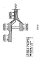
- the modems associated with the services to be provided are installed on a card. If 24 modems are located at each card, it is possible to install one card in every two out of the three systems illustrated in Fig. 7 and two cards in the third system. If a conventional method of "no sharing" is applied, 2 cards are needed for each system. Thus, instead of 6 cards that would be required in such a conventional system, the service provider applying the method of the present invention can use only 4 cards.
- the allocation of devices to enable proper sharing is done automatically, as will be further elaborated hereinafter.
- the 60 outputs are further divided into 45 "internal” outputs and 15 "global” outputs (capable of participating in the resources pool).
- the internal outputs are further divided into 15 internal groups of 3 outputs each.
- the 15 global outputs are also divided similarly - 5 groups of three outputs each.
- a basic matrix of 48x60 is used for the basic building block of the automatic MDF. This matrix is then connected to the various equipment cards.
- the 60 pairs extending towards the equipment (denoted as "outputs") are divided into two groups: one group is connected directly to the cards, while the other group (the “overflow” group) is not associated with any specific (dedicated) equipment.
- This latter group is further divided into two subgroups: one subgroup is connected internally to other layers, in our case this group has three subgroups, the three subgroups are connected to the three next floors in a "daisy chain" type of connection.
- the second overflow group exiting the system to be connected to other systems at the same location or at other nearby locations.
- the 48 lines for conveying overflow traffic, at the input and at the output, are divided into 2 groups of 24 lines. Each group can be connected to a different system.
- Fig. 9 demonstrates a modularity achieved by using multi-systems topology (the upper block is composed of two system and is similar to the lower block). As may be seen from Fig. 9 , two systems connected together may be considered as one, bigger system. Similarly, the system shown in Fig. 8 can also be considered as a consolidation of 8 smaller units - the 8 layers of the automated MDF.
- a configuration of Class "A” comprises one "layer” of automated MDF and its associated equipment units.
- the configuration designated as Class “B” comprises either multiple instances of Class "A” type configurations ("Class B1"), or, multiple instances of Class B1 type of configurations (“Class B2”), provided with the appropriate connectivity information and switching algorithm.
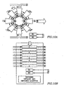
- Fig. 8 The system presented in Fig. 8 is also referred to in Figs. 10A and 10B .
- the system has a configuration which comprises 8 associated class A type building blocks.
- the network shown in Fig. 9 is referred to in Fig. 10C and 10D , showing a configuration comprising one class B2 type building block which is composed of 2 Class B1 type building blocks, each comprising a configuration composed of eight Class A type building blocks.
- the network shown in Figs. 10C and 10D is composed of 4 street cabinets. Each of the street cabinets is a building block of the type Class B1, composed of 8 building blocks of Class A.
- the overall network is an instance of class B2 composed of 4 instances of class B1 (the upper left street cabinet in the network shown in Figs. 10C and 10D has 3 overflows groups and not 2 as previously described in connectior with Fig. 8 , therefore, the connectivity information in the specific Class A is different than that described.
- the building blocks are still considered to be Class A instances with different internal information, while the system itself is still a class "B" system with the specific class "A" instances.
- the overflow inputs and outputs are not necessarily increased for large networks.
- large networks may be confined to themselves without the need to get, or provide backup from/to other external systems, which is consistent with the law of large numbers.
- An autonomus network ('autonomus' in the sense that it is confined by itself) of 4 systems of 400 customers each, needs only half of the excess equipment when compared to 4 autonomus systems of 400 customers each.
- Fig. 11 demonstrates the scalability effect when allowing different blocking probabilities.
- y axis shows the excess of equipment (in percentage) used for achieving a specific availability failure and being a function of the number of customers (x axis).
- the penetration value for this graph is assumed to be 10%.
- street cabinet 120 has two adjacent street cabinets 122 and 124 that are connected to cabinet 120 via the 24 input/output line pairs.
- the systems automatically detect the presence of each other and register possible connectivity features. The detection is done through the use of local communications exchanged between the two systems. For this purpose an additional twisted pair, the 25th, may be used, that extends between these street cabinets. This 25th pair may either by a pair dedicated for such local communications, or a pair which may carry other communications, apart from those required for the local communications referred to above.
- V22 modems are used for the communications.
- the term "outputs" as referred to in the example will be the 'DTE' section of the modem while the term “inputs” of the example will refer to the 'DCE' section of the modem, as may be seen in Fig. 12 .
- the same pair may also be used for local communications to be carried between these two systems.
- each system receives the connectivity information from all nearby systems, while any information regarding systems located over the horizon distance will be discarded by or not communicated to that system.
- Such horizon distance is for example a pre-determined value, preferably associated with a certain type of service, where each different service may be associated with a different horizon distance. For example for POTS this distance could be determined as 3000m, for ADSL 2000m, for VDSL 500m, etc.).
- the truncated information is stored at the CPU memory and is transferred to all adjacent neighbors, and each neighbor will truncate the information to the desired length according to its own position. The result will be a limited amount of connectivity information stored at each street cabinet, which information relates only to the nearby systems in the respective connectivity horizon radius.
- Fig. 15 illustrates the scalability that may be achieved when each system stores only limited number of connections and transact only this limited number to its neighbors. All 8 systems surrounding the middle system 150 transfer the truncated information they had calculated and stored, to their neighbors. System 150 receives all the information, truncates it in accordance with its own local horizon and propagates it also to its neighbors. For clarity purposes, only one type of service is shown in Fig. 15 .
- each system Since the horizon of each system is preferably limited, propagation delays that might limit the protocol performance in ordinary routers, are negligible in this case, as it concerns only a limited number of systems in the vicinity of any specific system.
- the rate of changes in each system would typically be in a range of once a day to once a week. Such changes may easily propagate by the protocol used.
- the structure named "System” may comprise the system identification number, its distance and a set of available services. Each service has its type and its identification number.
- the transaction sends all the information in Sys[M].
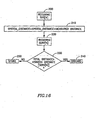
- the receiver adds the distance from the transmitted unit to the overall distance, discards all services associated with distance(s) higher then the connectivity horizon and adds its own system structure (that obviously has 0 distance). The steps associated with such a method are demonstrated in Fig.
- the street cabinet receives the system's details such as its identification number, its distance and a set of available services (step 200), determine the distance as being equal to the distance provided within that communication plus the distance measured at that street cabinet of the distance which was traveled by the communication received (step 210), retrieves the services available in the system (step 220) and determines (step 130) whether the horizon distance is lower for any given service from the distance determined in step 210.
- all information related to services having an horizon distance higher than the distance determined in step 210 are discarded (step 240) whereas the information related to all services associated with an horizon distance lower than the distance determined in step 110 are stored (step 250).
- a device 300 constructed in accordance with the present invention is used.
- the device comprises an interfacing MDF 302 which is connected directly to the customer's premises 308 (the "inputs" side) and an interfacing MDF that is connected directly to the exchange side and/or to other street cabinets (the “outputs" side). All functions required for operating automatic MDF and providing VDSL services to the customers may be implemented after the installation of device 300, as traffic will be routed via routing device 306.
- legacy installation 310 has already been provided with MDF devices, at the CO side and the customers' side, 314 and 312, respectively.
- the legacy MDF can be maintained and the relevant lines will be rerouted through the upgrading device 320 which comprises the two corresponding MDF interfaces 322 and 324, and the routing device 326, allowing the relevant lines to be provided with all the features of automated MDF as explained above in connection with Fig. 17 .
- Automated MDF reduces the need for technicians to visit the street cabinet whenever a new provisioning, or disconnecting of customers, is required and customers will be able to be provided with the new service in a matter of hours rather than in days.
- testing resources may be added to the arrangement provided so that lines will be routed to the testing resource whenever fault is suspected. Since the line-testing card should not be installed in all systems but only in a small fraction thereof, as all systems located at the vicinity of a system at which such a line-testing card has been installed could use this resource through the sharing feature of the present invention.
Landscapes
- Engineering & Computer Science (AREA)
- Computer Networks & Wireless Communication (AREA)
- Data Exchanges In Wide-Area Networks (AREA)
Claims (11)
- Ein Zugangskommunikationssystem, das Folgendes umfasst:eine erste Vielzahl von Kommunikationsvorrichtungen, von denen jede ausgebildet ist, um mit einem Teilnehmer aus einer zweiten Vielzahl von Teilnehmern zu kommunizieren, die mit dem Zugangskommunikationssystem verknüpft sind,mindestens eine Aggregationsvorrichtung (300), die mindestens eine automatisierte Schaltmatrix (302) umfasst, die mit einer dritten Vielzahl von Kommunikationsvorrichtungen verbunden ist, gewählt aus der ersten Vielzahl von Kommunikationsvorrichtungen, und die mit einer vierten Vielzahl von Teilnehmern verbunden ist, gewählt aus der zweiten Vielzahl von Teilnehmern, und wobei die automatisierte Schaltmatrix (302) Mittel zur Verbindung eines neuen Teilnehmers (308) durch die mindestens eine Aggregationsvorrichtung umfasst, die die Bereitstellung eines erforderlichen Dienstes an den neuen Teilnehmer (308) ermöglichen, entweder durch Verwendung einer aus der dritten Vielzahl von Kommunikationsvorrichtungen oder durch Kommunikation mit einer Kommunikationsvorrichtung, die an einem anderen Ort installiert ist und die wirksam ist, um die Bereitstellung des Dienstes, der von dem neuen Teilnehmer (308) angefordert wird, zu ermöglichen, undwobei das Zugangskommunikationssystem weiter dadurch gekennzeichnet ist, dass die Anzahl der zweiten Vielzahl von Teilnehmern größer ist als die Anzahl der ersten Vielzahl von Kommunikationsvorrichtungen.
- Ein Zugangskommunikationssystem gemäß Anspruch 1, wobei die Aggregationsvorrichtung (300) gewählt ist aus der Gruppe bestehend aus einem MSAG, einem DSLAM, einem Kommunikations-Regal, das sich in einem Straßenschrank befindet, und einem Kommunikations-Regal, das sich in der Fernsprechvermittlungsstelle befindet.
- Ein Zugangskommunikationssystem gemäß Anspruch 2, wobei sich die Aggregationsvorrichtung (300) ein MSAG ist, das sich in einem Straßenschrank befindet, und wobei die Kommunikationsvorrichtung, die an einem anderen Ort installiert ist, in einem Straßenschrank in der Nähe installiert ist.
- Ein Zugangskommunikationssystem gemäß Anspruch 1, wobei jeder der Dienste, die von dem Zugangskommunikationsnetz bereitgestellt werden, mit einer vordefinierten Kennzeichnungsdistanz verknüpft ist und wobei jeder der dritten Vielzahl von Teilnehmern entweder über die Aggregationsvorrichtung (300) zur Bereitstellung von Diensten, die von jedem der dritten Vielzahl von Teilnehmern angefordert werden, angeschlossen werden kann, oder über eine zweite Aggregationsvorrichtung, die eine fünfte Vielzahl von Kommunikationsvorrichtungen umfasst, angeschlossen werden kann, vorausgesetzt, dass die Distanz, die sich zwischen jedem der Teilnehmer aus der dritten Vielzahl von Teilnehmern und der jeweiligen Kommunikationsvorrichtung erstreckt, ob in der Aggregationsvorrichtung (300) oder in der zweiten Aggregationsvorrichtung installiert, geringer ist als die entsprechende vordefinierte Kennzeichnungsdistanz.
- Ein Zugangskommunikationssystem gemäß Anspruch 1, wobei die mindestens eine Aggregationsvorrichtung (300) und die dritte Vielzahl von Kommunikationsvorrichtungen von einem Verwaltungssystem verwaltet werden.
- Ein Zugangskommunikationssystem gemäß Anspruch 5, wobei das Verwaltungssystem eine einzige lokale Verwaltungseinheit umfasst, die wirksam ist, um die mindestens eine Aggregationsvorrichtung (300) und die dritte Vielzahl von Kommunikationsvorrichtungen zu verwalten.
- Eine Kommunikationsaggregationsvorrichtung (300), ausgebildet, um in einem Zugangskommunikationssystem zu arbeiten, und Folgendes umfassend:mindestens eine Schnittstelle, die wirksam ist, um die Kommunikation mit einer Vielzahl von Teilnehmern zu ermöglichen,eine Vielzahl von Kommunikationsvorrichtungen, die wirsam sind, um gleichzeitig weniger als allen der Vielzahl von Teilnehmern erforderliche Dienste bereitzustellen,Mittel, die wirksam sind, um zu bestimmen, falls ein neuer Teilnehmer durch die Kommunikationsaggregationsvorrichtung (300) angeschlossen werden soll, ob der Dienst, der für den neuen Teilnehmer erforderlich ist, mit Hilfe einer aus der Vielzahl von Kommunikationsvorrichtungen oder durch eine Kommunikationsvorrichtung bereitgestellt werden soll, die an einem anderen Ort installiert ist,mindestens eine automatisierte Schaltmatrix (302), die wirksam ist, um einen Teilnehmer mit einer verfügbaren Kommunikationsvorrichtung zu verknüpfen, und im Falle eines neuen Teilnehmers (308), um die Bereitstellung des erforderlichen Dienstes in Übereinstimmung mit den Bestimmungsmitteln zu ermöglichen.
- Eine Kommunikationsaggregationsvorrichtung (300) gemäß Anspruch 7, die weiter Folgendes umfasst:Mittel, die wirksam sind, um eine verfügbare Kommunikationsvorrichtung, durch welche der Dienst, der für den neuen Teilnehmer erforderlich ist, bereitgestellt werden kann, aus der Vielzahl von Kommunikationsvorrichtungen in der Kommunikationsaggregationsvorrichtung (300) auszuwählen,Prozessor, der wirksam ist, um eine maximale Distanz im Zusammenhang mit dem Dienst, der für den neuen Teilnehmer (308) erforderlich ist, festzulegen,Mittel, die wirksam sind, um die Verfügbarkeit einer Kommunikationsvorrichtung zu bestimmen, die ausgebildet ist, um den Dienst, der für den neuen Teilnehmer (308) erforderlich ist, bereitzustellen, wobei letztere Kommunikationsvorrichtung mit einer zweiten Kommunikationsaggregationsvorrichtung verknüpft ist, die sich innerhalb der maximalen Distanz von dem neuen Teilnehmer (308) befindet.
- Eine Kommunikationsaggregationsvorrichtung (300) gemäß Anspruch 7, wobei jede der Kommunikationsvorrichtungen ein Modem ist, das mit einer Rate arbeitet, die zur Bereitstellung eines Dienstes kompatibel ist, der von einem Teilnehmer angefordert wird, mit welchem das Modem verbunden wird.
- Eine Kommunikationsaggregationsvorrichtung (300) gemäß Anspruch 7, weiter dadurch gekennzeichnet, dass die mindestens eine automatisierte Schaltmatrix (302) und die Vielzahl von Kommunikationsvorrichtungen von einer einzigen Verwaltungseinheit verwaltet werden.
- Ein Verfahren zur Verknüpfung eines Straßenschranks (120) mit einem Zugangskommunikationssystem gemäß Anspruch 1, das Folgendes umfasst:(i) Bereitstellung einer Eingabeschnittstelle, die mit einer Vielzahl von Teilnehmern verbunden ist, und einer Ausgabeschnittstelle, die mit einer Vermittlungsstellenseite und/oder mit einem oder mehreren anderen Straßenschränken (122, 124) verbunden ist,(ii) Ermöglichen der Festlegung einer maximalen Distanz für jede Art von Diensten, die von jedem der Vielzahl von Teilnehmern angefordert werden,(iii) Auswahl verfügbarer Kommunikationsvorrichtungen, die geeignet sind, Teilnehmern, denen die erforderlichen Dienste nicht von irgendeiner Kommunikationsvorrichtung bereitgestellt werden können, die in dem Straßenschrank (120) installiert ist, erforderliche Dienste bereitzustellen, wobei die Auswahl unter Anwendung eines Kriteriums vorgenommen wird, dass jede der ausgewählten Kommunikationen sich jeweils innerhalb der festgelegten maximalen Distanz von einem entsprechenden Teilnehmer befindet, dem der erforderliche Dienst zur Verfügung gestellt werden sollte,(iv) Ermöglichen von Kommunikation zwischen Teilnehmern, denen die erforderlichen Dienste nicht von Kommunikationsvorrichtungen bereitgestellt werden, die sich in dem Straßenschrank (120) befinden, und den ausgewählten Kommunikationsvorrichtungen.
Applications Claiming Priority (2)
| Application Number | Priority Date | Filing Date | Title |
|---|---|---|---|
| IL171722A IL171722A (en) | 2005-11-01 | 2005-11-01 | Access system for the provisioning of different communication services and method for using same |
| PCT/IL2006/001236 WO2007052254A1 (en) | 2005-11-01 | 2006-10-26 | Access system for the provisioning of different communication services, and method for using same |
Publications (2)
| Publication Number | Publication Date |
|---|---|
| EP1943843A1 EP1943843A1 (de) | 2008-07-16 |
| EP1943843B1 true EP1943843B1 (de) | 2012-05-16 |
Family
ID=37667148
Family Applications (1)
| Application Number | Title | Priority Date | Filing Date |
|---|---|---|---|
| EP06809797A Not-in-force EP1943843B1 (de) | 2005-11-01 | 2006-10-26 | Zugangssystem zur bereitstellung verschiedener kommunikationsdienste und verfahren zu seiner benutzung |
Country Status (4)
| Country | Link |
|---|---|
| US (1) | US20080291897A1 (de) |
| EP (1) | EP1943843B1 (de) |
| IL (1) | IL171722A (de) |
| WO (1) | WO2007052254A1 (de) |
Families Citing this family (5)
| Publication number | Priority date | Publication date | Assignee | Title |
|---|---|---|---|---|
| US10404615B2 (en) | 2012-02-14 | 2019-09-03 | Airwatch, Llc | Controlling distribution of resources on a network |
| US9680763B2 (en) | 2012-02-14 | 2017-06-13 | Airwatch, Llc | Controlling distribution of resources in a network |
| US20140280955A1 (en) | 2013-03-14 | 2014-09-18 | Sky Socket, Llc | Controlling Electronically Communicated Resources |
| US9401915B2 (en) * | 2013-03-15 | 2016-07-26 | Airwatch Llc | Secondary device as key for authorizing access to resources |
| US9584964B2 (en) | 2014-12-22 | 2017-02-28 | Airwatch Llc | Enforcement of proximity based policies |
Family Cites Families (16)
| Publication number | Priority date | Publication date | Assignee | Title |
|---|---|---|---|---|
| US4355207A (en) * | 1980-05-30 | 1982-10-19 | Amtel Communications, Inc. | Telephone answering system |
| US5287537A (en) * | 1985-11-15 | 1994-02-15 | Data General Corporation | Distributed processing system having plural computers each using identical retaining information to identify another computer for executing a received command |
| US5270701A (en) * | 1988-03-08 | 1993-12-14 | Kokusai Denshin Denwa Co., Ltd. | Service processing system with distributed data bases |
| US5063351A (en) * | 1990-09-24 | 1991-11-05 | Bell Communications Research, Inc. | Digital signal processing relating to near-end crosstalk cable measurements |
| US5532603A (en) * | 1995-01-27 | 1996-07-02 | Fluke Corporation | Cross-talk measurement apparatus with near-end compensation |
| US6317495B1 (en) * | 1997-12-19 | 2001-11-13 | Wm. Marsh Rice University | Spectral optimization and joint signaling techniques with multi-line separation for communication in the presence of crosstalk |
| US6671259B1 (en) * | 1999-03-30 | 2003-12-30 | Fujitsu Limited | Method and system for wide area network load balancing |
| US6711159B1 (en) * | 1999-12-15 | 2004-03-23 | 3Com Corporation | Load balancing among media gateways |
| WO2002073889A1 (en) * | 2001-03-13 | 2002-09-19 | British Telecommunications Public Limited Company | Communications network |
| US7881208B1 (en) * | 2001-06-18 | 2011-02-01 | Cisco Technology, Inc. | Gateway load balancing protocol |
| US20030031239A1 (en) * | 2001-08-08 | 2003-02-13 | Posthuma Carl Robert | Maximizing DSL throughput |
| AU2003297255A1 (en) * | 2002-11-12 | 2004-06-03 | Utstarcom, Inc. | Method for frequency and loop length grouping for cross-talk reduction in a plurality of dsl channels |
| US7379419B2 (en) * | 2003-08-13 | 2008-05-27 | Samsung Electronics Co., Ltd. | Apparatus and method for performing an online software upgrade of resource servers |
| US20060092950A1 (en) * | 2004-10-28 | 2006-05-04 | Cisco Technology, Inc. | Architecture and method having redundancy in active/active stateful devices based on symmetric global load balancing protocol (sGLBP) |
| US7613111B2 (en) * | 2005-04-18 | 2009-11-03 | Santera Systems, Llc | Methods, systems, and computer program products for dynamic blocking an unblocking of media over packet resources |
| US20070070959A1 (en) * | 2005-09-23 | 2007-03-29 | Almeroth Kevin C | Infrastructure mesh networks |
-
2005
- 2005-11-01 IL IL171722A patent/IL171722A/en not_active IP Right Cessation
-
2006
- 2006-10-26 US US12/092,214 patent/US20080291897A1/en not_active Abandoned
- 2006-10-26 WO PCT/IL2006/001236 patent/WO2007052254A1/en not_active Ceased
- 2006-10-26 EP EP06809797A patent/EP1943843B1/de not_active Not-in-force
Also Published As
| Publication number | Publication date |
|---|---|
| IL171722A (en) | 2011-12-29 |
| WO2007052254A1 (en) | 2007-05-10 |
| US20080291897A1 (en) | 2008-11-27 |
| EP1943843A1 (de) | 2008-07-16 |
Similar Documents
| Publication | Publication Date | Title |
|---|---|---|
| CA2354955C (en) | System and method for providing analog telephone service when voice over ip over sdsl service is interrupted due to power failure | |
| US5796953A (en) | System having user terminal connecting to a remote test system via the internet for remotely testing communication network | |
| US20040120508A1 (en) | Systems and methods for managing digital subscriber line (DSL) telecommunications connections | |
| CN1388699A (zh) | 用于多户住宅单元/多租户单元的交换电信服务系统以及方法 | |
| US20100027557A1 (en) | Systems and Methods for Allocating Bonding Engines in Network Communications | |
| EP1943843B1 (de) | Zugangssystem zur bereitstellung verschiedener kommunikationsdienste und verfahren zu seiner benutzung | |
| AU760623B2 (en) | Local switch | |
| WO2005091613A1 (en) | Method and system for providing xdsl and telephone service via telecommunication networks | |
| CN101427587B (zh) | 电信业务的提供 | |
| US20070211882A1 (en) | Control method for a telecommunication distribution system | |
| US20070211883A1 (en) | Telecommunications device having distribution units arranged in block configuration | |
| US8437344B2 (en) | Telecommunication distribution device with multi-circuit board arrangement | |
| US7039732B1 (en) | Method and apparatus for providing redundancy between card elements in a chassis | |
| US7920691B2 (en) | Method and apparatus for configuring an automatic cross connect system at a remote wiring hub | |
| KR20090007368A (ko) | 하이브리드 ip/atm dslam 및 하이브리드 ip/atm dsl 접근 다중화를 제공하는 방법 | |
| US8514880B2 (en) | Feature adaptable NT card | |
| US20070211740A1 (en) | Telecommunications distribution system with line sharing | |
| US20040005049A1 (en) | Apparatus and method for providing switching at a telephone cross-connect | |
| GB2432746A (en) | A flexible main distribution frame arrangement for connection of subscriber loops to a digital subscriber line interface | |
| JP5111749B2 (ja) | リモート配線ハブの自動交差接続システムを分解する装置 | |
| US6804328B1 (en) | Intelligent line testing | |
| CN1559149A (zh) | 提供clec到clec业务 | |
| KR100603583B1 (ko) | 아이피 네트워크를 이용한 교환시스템 및 그교환시스템에서의 노드간 연결 방법 | |
| Dimond et al. | Local Area Networks and Wide Area Networks | |
| WO2006079984A1 (en) | Method and system for provisioning broadband service |
Legal Events
| Date | Code | Title | Description |
|---|---|---|---|
| PUAI | Public reference made under article 153(3) epc to a published international application that has entered the european phase |
Free format text: ORIGINAL CODE: 0009012 |
|
| 17P | Request for examination filed |
Effective date: 20080502 |
|
| AK | Designated contracting states |
Kind code of ref document: A1 Designated state(s): AT BE BG CH CY CZ DE DK EE ES FI FR GB GR HU IE IS IT LI LT LU LV MC NL PL PT RO SE SI SK TR |
|
| 17Q | First examination report despatched |
Effective date: 20100217 |
|
| GRAP | Despatch of communication of intention to grant a patent |
Free format text: ORIGINAL CODE: EPIDOSNIGR1 |
|
| DAX | Request for extension of the european patent (deleted) | ||
| GRAS | Grant fee paid |
Free format text: ORIGINAL CODE: EPIDOSNIGR3 |
|
| GRAA | (expected) grant |
Free format text: ORIGINAL CODE: 0009210 |
|
| AK | Designated contracting states |
Kind code of ref document: B1 Designated state(s): AT BE BG CH CY CZ DE DK EE ES FI FR GB GR HU IE IS IT LI LT LU LV MC NL PL PT RO SE SI SK TR |
|
| REG | Reference to a national code |
Ref country code: GB Ref legal event code: FG4D |
|
| REG | Reference to a national code |
Ref country code: CH Ref legal event code: EP |
|
| REG | Reference to a national code |
Ref country code: AT Ref legal event code: REF Ref document number: 558551 Country of ref document: AT Kind code of ref document: T Effective date: 20120615 |
|
| REG | Reference to a national code |
Ref country code: IE Ref legal event code: FG4D |
|
| REG | Reference to a national code |
Ref country code: DE Ref legal event code: R096 Ref document number: 602006029562 Country of ref document: DE Effective date: 20120712 |
|
| REG | Reference to a national code |
Ref country code: NL Ref legal event code: VDEP Effective date: 20120516 |
|
| REG | Reference to a national code |
Ref country code: LT Ref legal event code: MG4D Effective date: 20120516 |
|
| PG25 | Lapsed in a contracting state [announced via postgrant information from national office to epo] |
Ref country code: SE Free format text: LAPSE BECAUSE OF FAILURE TO SUBMIT A TRANSLATION OF THE DESCRIPTION OR TO PAY THE FEE WITHIN THE PRESCRIBED TIME-LIMIT Effective date: 20120516 Ref country code: CY Free format text: LAPSE BECAUSE OF FAILURE TO SUBMIT A TRANSLATION OF THE DESCRIPTION OR TO PAY THE FEE WITHIN THE PRESCRIBED TIME-LIMIT Effective date: 20120516 Ref country code: PL Free format text: LAPSE BECAUSE OF FAILURE TO SUBMIT A TRANSLATION OF THE DESCRIPTION OR TO PAY THE FEE WITHIN THE PRESCRIBED TIME-LIMIT Effective date: 20120516 Ref country code: IS Free format text: LAPSE BECAUSE OF FAILURE TO SUBMIT A TRANSLATION OF THE DESCRIPTION OR TO PAY THE FEE WITHIN THE PRESCRIBED TIME-LIMIT Effective date: 20120916 Ref country code: LT Free format text: LAPSE BECAUSE OF FAILURE TO SUBMIT A TRANSLATION OF THE DESCRIPTION OR TO PAY THE FEE WITHIN THE PRESCRIBED TIME-LIMIT Effective date: 20120516 Ref country code: FI Free format text: LAPSE BECAUSE OF FAILURE TO SUBMIT A TRANSLATION OF THE DESCRIPTION OR TO PAY THE FEE WITHIN THE PRESCRIBED TIME-LIMIT Effective date: 20120516 |
|
| REG | Reference to a national code |
Ref country code: AT Ref legal event code: MK05 Ref document number: 558551 Country of ref document: AT Kind code of ref document: T Effective date: 20120516 |
|
| PG25 | Lapsed in a contracting state [announced via postgrant information from national office to epo] |
Ref country code: SI Free format text: LAPSE BECAUSE OF FAILURE TO SUBMIT A TRANSLATION OF THE DESCRIPTION OR TO PAY THE FEE WITHIN THE PRESCRIBED TIME-LIMIT Effective date: 20120516 Ref country code: GR Free format text: LAPSE BECAUSE OF FAILURE TO SUBMIT A TRANSLATION OF THE DESCRIPTION OR TO PAY THE FEE WITHIN THE PRESCRIBED TIME-LIMIT Effective date: 20120817 Ref country code: LV Free format text: LAPSE BECAUSE OF FAILURE TO SUBMIT A TRANSLATION OF THE DESCRIPTION OR TO PAY THE FEE WITHIN THE PRESCRIBED TIME-LIMIT Effective date: 20120516 Ref country code: PT Free format text: LAPSE BECAUSE OF FAILURE TO SUBMIT A TRANSLATION OF THE DESCRIPTION OR TO PAY THE FEE WITHIN THE PRESCRIBED TIME-LIMIT Effective date: 20120917 |
|
| PG25 | Lapsed in a contracting state [announced via postgrant information from national office to epo] |
Ref country code: BE Free format text: LAPSE BECAUSE OF FAILURE TO SUBMIT A TRANSLATION OF THE DESCRIPTION OR TO PAY THE FEE WITHIN THE PRESCRIBED TIME-LIMIT Effective date: 20120516 |
|
| PG25 | Lapsed in a contracting state [announced via postgrant information from national office to epo] |
Ref country code: CZ Free format text: LAPSE BECAUSE OF FAILURE TO SUBMIT A TRANSLATION OF THE DESCRIPTION OR TO PAY THE FEE WITHIN THE PRESCRIBED TIME-LIMIT Effective date: 20120516 Ref country code: RO Free format text: LAPSE BECAUSE OF FAILURE TO SUBMIT A TRANSLATION OF THE DESCRIPTION OR TO PAY THE FEE WITHIN THE PRESCRIBED TIME-LIMIT Effective date: 20120516 Ref country code: EE Free format text: LAPSE BECAUSE OF FAILURE TO SUBMIT A TRANSLATION OF THE DESCRIPTION OR TO PAY THE FEE WITHIN THE PRESCRIBED TIME-LIMIT Effective date: 20120516 Ref country code: SK Free format text: LAPSE BECAUSE OF FAILURE TO SUBMIT A TRANSLATION OF THE DESCRIPTION OR TO PAY THE FEE WITHIN THE PRESCRIBED TIME-LIMIT Effective date: 20120516 Ref country code: AT Free format text: LAPSE BECAUSE OF FAILURE TO SUBMIT A TRANSLATION OF THE DESCRIPTION OR TO PAY THE FEE WITHIN THE PRESCRIBED TIME-LIMIT Effective date: 20120516 Ref country code: NL Free format text: LAPSE BECAUSE OF FAILURE TO SUBMIT A TRANSLATION OF THE DESCRIPTION OR TO PAY THE FEE WITHIN THE PRESCRIBED TIME-LIMIT Effective date: 20120516 Ref country code: DK Free format text: LAPSE BECAUSE OF FAILURE TO SUBMIT A TRANSLATION OF THE DESCRIPTION OR TO PAY THE FEE WITHIN THE PRESCRIBED TIME-LIMIT Effective date: 20120516 |
|
| PG25 | Lapsed in a contracting state [announced via postgrant information from national office to epo] |
Ref country code: IT Free format text: LAPSE BECAUSE OF FAILURE TO SUBMIT A TRANSLATION OF THE DESCRIPTION OR TO PAY THE FEE WITHIN THE PRESCRIBED TIME-LIMIT Effective date: 20120516 |
|
| PLBE | No opposition filed within time limit |
Free format text: ORIGINAL CODE: 0009261 |
|
| STAA | Information on the status of an ep patent application or granted ep patent |
Free format text: STATUS: NO OPPOSITION FILED WITHIN TIME LIMIT |
|
| 26N | No opposition filed |
Effective date: 20130219 |
|
| PG25 | Lapsed in a contracting state [announced via postgrant information from national office to epo] |
Ref country code: ES Free format text: LAPSE BECAUSE OF FAILURE TO SUBMIT A TRANSLATION OF THE DESCRIPTION OR TO PAY THE FEE WITHIN THE PRESCRIBED TIME-LIMIT Effective date: 20120827 |
|
| PG25 | Lapsed in a contracting state [announced via postgrant information from national office to epo] |
Ref country code: MC Free format text: LAPSE BECAUSE OF NON-PAYMENT OF DUE FEES Effective date: 20121031 |
|
| REG | Reference to a national code |
Ref country code: CH Ref legal event code: PL |
|
| REG | Reference to a national code |
Ref country code: DE Ref legal event code: R097 Ref document number: 602006029562 Country of ref document: DE Effective date: 20130219 |
|
| REG | Reference to a national code |
Ref country code: IE Ref legal event code: MM4A |
|
| REG | Reference to a national code |
Ref country code: FR Ref legal event code: ST Effective date: 20130628 |
|
| PG25 | Lapsed in a contracting state [announced via postgrant information from national office to epo] |
Ref country code: IE Free format text: LAPSE BECAUSE OF NON-PAYMENT OF DUE FEES Effective date: 20121026 Ref country code: DE Free format text: LAPSE BECAUSE OF NON-PAYMENT OF DUE FEES Effective date: 20130501 Ref country code: CH Free format text: LAPSE BECAUSE OF NON-PAYMENT OF DUE FEES Effective date: 20121031 Ref country code: LI Free format text: LAPSE BECAUSE OF NON-PAYMENT OF DUE FEES Effective date: 20121031 Ref country code: BG Free format text: LAPSE BECAUSE OF FAILURE TO SUBMIT A TRANSLATION OF THE DESCRIPTION OR TO PAY THE FEE WITHIN THE PRESCRIBED TIME-LIMIT Effective date: 20120816 |
|
| REG | Reference to a national code |
Ref country code: DE Ref legal event code: R119 Ref document number: 602006029562 Country of ref document: DE Effective date: 20130501 |
|
| PG25 | Lapsed in a contracting state [announced via postgrant information from national office to epo] |
Ref country code: FR Free format text: LAPSE BECAUSE OF NON-PAYMENT OF DUE FEES Effective date: 20121031 |
|
| PGFP | Annual fee paid to national office [announced via postgrant information from national office to epo] |
Ref country code: GB Payment date: 20130923 Year of fee payment: 8 |
|
| PG25 | Lapsed in a contracting state [announced via postgrant information from national office to epo] |
Ref country code: TR Free format text: LAPSE BECAUSE OF FAILURE TO SUBMIT A TRANSLATION OF THE DESCRIPTION OR TO PAY THE FEE WITHIN THE PRESCRIBED TIME-LIMIT Effective date: 20120516 |
|
| PG25 | Lapsed in a contracting state [announced via postgrant information from national office to epo] |
Ref country code: LU Free format text: LAPSE BECAUSE OF NON-PAYMENT OF DUE FEES Effective date: 20121026 |
|
| PG25 | Lapsed in a contracting state [announced via postgrant information from national office to epo] |
Ref country code: HU Free format text: LAPSE BECAUSE OF FAILURE TO SUBMIT A TRANSLATION OF THE DESCRIPTION OR TO PAY THE FEE WITHIN THE PRESCRIBED TIME-LIMIT Effective date: 20061026 |
|
| GBPC | Gb: european patent ceased through non-payment of renewal fee |
Effective date: 20141026 |
|
| PG25 | Lapsed in a contracting state [announced via postgrant information from national office to epo] |
Ref country code: GB Free format text: LAPSE BECAUSE OF NON-PAYMENT OF DUE FEES Effective date: 20141026 |