EP1944108A2 - Tête de forage pour un outil de forage et outil de forage - Google Patents
Tête de forage pour un outil de forage et outil de forage Download PDFInfo
- Publication number
- EP1944108A2 EP1944108A2 EP08003707A EP08003707A EP1944108A2 EP 1944108 A2 EP1944108 A2 EP 1944108A2 EP 08003707 A EP08003707 A EP 08003707A EP 08003707 A EP08003707 A EP 08003707A EP 1944108 A2 EP1944108 A2 EP 1944108A2
- Authority
- EP
- European Patent Office
- Prior art keywords
- cutting edge
- head according
- drill
- face
- drill head
- Prior art date
- Legal status (The legal status is an assumption and is not a legal conclusion. Google has not performed a legal analysis and makes no representation as to the accuracy of the status listed.)
- Granted
Links
- 238000005553 drilling Methods 0.000 claims abstract description 50
- 230000002093 peripheral effect Effects 0.000 claims description 44
- 239000000428 dust Substances 0.000 claims description 8
- 230000007423 decrease Effects 0.000 claims description 6
- 239000011435 rock Substances 0.000 claims description 6
- 239000004575 stone Substances 0.000 abstract 1
- 239000007787 solid Substances 0.000 description 6
- 239000002184 metal Substances 0.000 description 5
- 239000000463 material Substances 0.000 description 3
- 238000005299 abrasion Methods 0.000 description 2
- 238000004519 manufacturing process Methods 0.000 description 2
- 230000001010 compromised effect Effects 0.000 description 1
- 230000003247 decreasing effect Effects 0.000 description 1
- 235000012054 meals Nutrition 0.000 description 1
- 238000010008 shearing Methods 0.000 description 1
- 230000007704 transition Effects 0.000 description 1
Images


Classifications
-
- E—FIXED CONSTRUCTIONS
- E21—EARTH OR ROCK DRILLING; MINING
- E21B—EARTH OR ROCK DRILLING; OBTAINING OIL, GAS, WATER, SOLUBLE OR MELTABLE MATERIALS OR A SLURRY OF MINERALS FROM WELLS
- E21B10/00—Drill bits
- E21B10/44—Bits with helical conveying portion, e.g. screw type bits; Augers with leading portion or with detachable parts
- E21B10/445—Bits with helical conveying portion, e.g. screw type bits; Augers with leading portion or with detachable parts percussion type, e.g. for masonry
-
- B—PERFORMING OPERATIONS; TRANSPORTING
- B23—MACHINE TOOLS; METAL-WORKING NOT OTHERWISE PROVIDED FOR
- B23B—TURNING; BORING
- B23B51/00—Tools for drilling machines
-
- B—PERFORMING OPERATIONS; TRANSPORTING
- B23—MACHINE TOOLS; METAL-WORKING NOT OTHERWISE PROVIDED FOR
- B23B—TURNING; BORING
- B23B2222/00—Materials of tools or workpieces composed of metals, alloys or metal matrices
- B23B2222/28—Details of hard metal, i.e. cemented carbide
-
- B—PERFORMING OPERATIONS; TRANSPORTING
- B23—MACHINE TOOLS; METAL-WORKING NOT OTHERWISE PROVIDED FOR
- B23B—TURNING; BORING
- B23B2226/00—Materials of tools or workpieces not comprising a metal
- B23B2226/75—Stone, rock or concrete
-
- B—PERFORMING OPERATIONS; TRANSPORTING
- B23—MACHINE TOOLS; METAL-WORKING NOT OTHERWISE PROVIDED FOR
- B23B—TURNING; BORING
- B23B2251/00—Details of tools for drilling machines
- B23B2251/14—Configuration of the cutting part, i.e. the main cutting edges
-
- B—PERFORMING OPERATIONS; TRANSPORTING
- B23—MACHINE TOOLS; METAL-WORKING NOT OTHERWISE PROVIDED FOR
- B23B—TURNING; BORING
- B23B2251/00—Details of tools for drilling machines
- B23B2251/18—Configuration of the drill point
-
- B—PERFORMING OPERATIONS; TRANSPORTING
- B23—MACHINE TOOLS; METAL-WORKING NOT OTHERWISE PROVIDED FOR
- B23B—TURNING; BORING
- B23B2251/00—Details of tools for drilling machines
- B23B2251/50—Drilling tools comprising cutting inserts
-
- B—PERFORMING OPERATIONS; TRANSPORTING
- B23—MACHINE TOOLS; METAL-WORKING NOT OTHERWISE PROVIDED FOR
- B23B—TURNING; BORING
- B23B2270/00—Details of turning, boring or drilling machines, processes or tools not otherwise provided for
- B23B2270/30—Chip guiding or removal
Definitions
- the invention relates to a drill head for a drilling tool, in particular a rock drill and / or concrete drill.
- a drill head for a drilling tool, in particular a rock drill and / or concrete drill.
- the drill head has to endure the significant drilling loads, which is why a hard metal is usually used for the drill head.
- the drill head should achieve effective material removal with little wear.
- a drilling tool with a shank and a drill head which is provided with a slot in which a drill plate is made, which is made of a hard metal.
- the abrasion of rock material is realized by the drill plate, which has an end face in side view a V-shaped main cutting edge.
- the basic shape of the drill plate which is rectangular in plan view, has radial, triangular widenings.
- solid carbide heads As for example from the DE 43 39 245 A1 are known.
- the known solid carbide head is characterized by a polygonal symmetrical shape, which is connected via a kind of tongue and groove connection with the front end of a helical shaft of the drilling tool.
- difficulties a fixed mounting of the carbide heads to the helical shank of the drilling tool.
- the high cost of carbide material for the realization of the solid drill head represents a significant cost factor.
- An alternative drill head is in the EP 0 884 448 B1 proposed a substantially prismatic body with a substantially X-shaped in a plan view Basic shape has.
- the drill head has a central axis, which coincides in the monited state of the drill head with the Bohrwerkmaschineachse.
- the drill head has a mounting side on which it is to be attached to a front end of the drilling tool, in particular in a corresponding X-shaped groove in the front end of the drilling tool is to be used.
- the drill head has a diametrically opposite end of the mounting, on which a main cutting edge and a minor cutting edge are formed.
- the drill head has two diametrically opposite, substantially in the axial direction extending discharge groove bounding V-shaped side surfaces, to each of which one of the two conveyor coils of the shaft of the drilling tool extend.
- the drill head comprises two diametrically opposed, axially extending peripheral sides, which, viewed in the circumferential direction of the drill head, lie between the two V-shaped side surfaces.
- the peripheral sides are circumferentially bounded by a trailing in the direction of rotation of the drill head axial edge and a radially recessed, leading in the direction of rotation axial edge. In both peripheral sides grooves are introduced for the removal of drill dust from the respective cutting edges.
- a minor cutting edge is arranged in such a way to the main cutting edge that it protrudes axially on the periphery side over the main cutting edge. It has been found that in the generic drill head difficulties due to the distinctive side cutting profile of a dimensionally accurate, repeatable production of the drill head exist. Furthermore, the effectiveness of the drill bit appeared to be compromised due to poor removal of debris, particularly away from the main cutting edge.
- EP 1 125 663 A2 and EP 1 125 664 A2 disclose a drilling tool having a solid carbide head with a face on which major and minor cutting edges are formed.
- the solid carbide head has a substantially cross shape with four over the peripheral edge of the shank protruding cutting arms, each forming a major or minor cutting edge.
- a drill head wherein the peripheral side an axially extending Deepening for the removal of drilling dust towards a conveying spiral of a shaft of the drilling tool, which is bounded by two axially extending webs in the circumferential direction.
- at least one of the webs preferably both webs, has an increasing in the axial direction of the end face circumferential direction component.
- the provided with circumferential direction component for example, helical extension of the discharge recess in the peripheral side ensures active removal of drilling dust away from the front and their cutting. Due to the special shape of the recess, the rotation of the drill head supports the drilling dust removal.
- At least one of the webs is / are curved, wherein in particular the curvature is continuous towards a conveying helix of a drilling tool shaft mounted on the mounting side.
- both webs may be curved such that their distance in the extension direction of the recess remains substantially the same.
- the width of the recess increases toward the mounting side.
- the depression extends helical from the front side to the mounting side.
- At least one of the peripheral sides of the drill bit includes a radially convex curve having a radius with respect to the central axis that continuously decreases continuously in a circumferential direction of the drill bit along the entire periphery side.
- the peripheral side is shaped according to the drilling groove to be created, with the radius of the peripheral side slightly decreasing in the direction of rotation.
- Particularly preferred is a continuous steady decrease of the peripheral side radius opposite to the direction of rotation of the drilling tool.
- the service life of the drill head are significantly extended because introduced by the Abgaunut weak points on the periphery side are now lacking and the convex periphery side clean management of the drill head in the created Drill groove ensures.
- At least one of the peripheral sides preferably both peripheral sides, an axial edge leading in the direction of rotation and an axial edge trailing in the direction of rotation, wherein the radius of the trailing axial edge is set back radially with respect to the radius of the leading axial edge and the Radius of the periphery side between the leading edge and the trailing edge of the radius of the radius decreases slightly continuously steadily.
- the radial offset of the trailing axial edge corresponds to about less than 10%, preferably about 8%, of the center distance of the leading axial edge.
- a main cutting edge of the central axis is rectilinear and radially aligned.
- the main cutting edge extends like a diagonal of the front side of the central axis, in particular in the radial direction kink-free towards both peripheral sides.
- the main cutting edges preferably open into the peripheral sides with respect to the radial direction without interruption.
- the measure according to the invention surprisingly also achieves an ergonomic improvement in the handling of the boring tool provided with the boring head according to the invention, since a simple position-stable boring is ensured by the rectilinear, radial main cutting edge through the center axis.
- the service life of the drill head is extended due to the steady course of the main cutting edge.
- the main cutting edge divides the end face into two, in particular identical, end side wings, which drop from the main cutting edge to the respective V-shaped side face of the drill head.
- the front side wing may be curved axially concave, and in particular the other end wing, however, may be flat, preferably both end wings are curved axially concave.
- at least one axial, protruding from the end face projection preferably two axial projections, each having a secondary cutting edge formed on a front side wing, which extends from a surface leg of the V-shaped side surface at least partially to the main cutting edge.
- the main cutting edge may have a first, in particular constant, angle of inclination and, for a mid-axis-side section, a second, in particular constant, angle of inclination, which is acute-angled and greater than the first angle of inclination with respect to a radial plane to which the central axis is a plane normal.
- a secondary cutting edge formed on the end face can intersect the main cutting edge in the central axis and extend to the V-shaped side faces.
- the secondary cutting edge and the main cutting edge open into a common point-shaped tip, in particular, through which the center axis passes.
- the end face may preferably be at least partially pyramidal.
- both the minor cutting edge and the main cutting edge may be inclined to a radial plane to which the central axis is a plane normal.
- the secondary cutting edge is radially, in particular curved such that the secondary cutting edge has an S-shape in plan view.
- the secondary cutting edge can be curved axially concave.
- At least one groove preferably two grooves, which are point-symmetrical with respect to the central axis, are formed on the end face for the removal of drilling dust.
- the channel extends from a peripheral side and opens into a surface leg of the V-shaped side surface, preferably tapering.
- the channel may be formed by a recess with an axially concave, in particular part-cylindrical bottom.
- the channel has a first, in particular, part-truncated cone-shaped section, which extends in a tapering manner from the periphery side towards the central axis, preferably a second part-truncated cone-shaped section adjoining the first channel section and, in particular, flaring or tapering into the surface leg.
- the channel sections are at an obtuse angle to each other.
- the first channel section is located in the middle in the end face and extending from the periphery side to at least halfway to the central axis radially.
- a main cutting edge divides the end face into two end side wings, wherein the gutter is incorporated in the front side wing trailing in particular in the direction of rotation.
- the main cutting edge preferably coincides at least approximately with a boundary edge of the groove.
- a connection channel formed on the front side opens into the channel from the surface leg leading in the direction of rotation of the V-shaped side surface.
- the connecting channel has a smaller axial depth than the channel and / or is introduced in the peripheral side near the front side. At least in the region of the periphery side, the channel can occupy at least 50%, preferably more than 60%, of the radial width of the front side.
- the drill bit forms a substantially prismatic body having a generally X-shaped plan view in a plan view defined by the opposing V-shaped side surfaces.
- the body has a radial constriction substantially at the height of the central axis, wherein in particular the radial width of the constriction corresponds to at least 30%, preferably at least over 40%, in particular over 50%, of the radial maximum width of the body in the region of the periphery side.
- the body can be formed from a hard metal piece, in particular sintered.
- the invention relates to a drilling tool especially for rock and / or concrete with a drill head according to the invention, the drilling tool facing mounting side is to be attached to a front end of a shaft of the drilling tool, in particular inserted into a groove in the front end and fixed, in particular soldered.
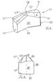
- a first embodiment of the drill head is generally indicated at reference numeral 101.
- the drill head 101 is made of a hard metal piece to a one-piece body, which is essentially defined by four main sides, namely a mounting side 103, which is to face a front end of a drilling tool, not shown in the assembly of the drill head 101; a mounting side opposite end face 105, which is provided with cutting edges; two diametrically opposite peripheral sides 107, which opens into both the end face 105 and the mounting side 103, and two diametrically opposite, V-shaped side surfaces 109th
- the drill head 101 is provided at the end face 105 with a relative to a radial direction, straight, through a central axis M of the drill head radially extending main cutting edge 111, the rectilinearly from the periphery side 107, continuously across an entire front half to the central axis M extends and there kinking in the axial direction to form a punctiform tip and with the same slope straight and kink-free to the opposite periphery side 107 extends.
- the main cutting edge 111 divides the end face 105 into two point-symmetrical front side wings.
- the drill head 101 has a substantially prismatic body with two pairs of parallel surface legs 113, 115 and 117, 119 of the V-shaped side surfaces.
- the two V-shaped side surface 109 forming surface legs 113, 117 and 115, 119 span an obtuse angle ⁇ of about 152 °.
- the body of the drill head 101 comprises, at the level of the center axis M, a constriction 121 whose radial width b corresponds to at least 50% of the maximum radial width B on the periphery side 107.
- a first secondary cutting edge 125 intersects the main cutting edge 111 in the central axis M and forms an obtuse angle with the main cutting edge 111 and extends substantially over half the width b of the drill head 101 in the region of the constriction 121.
- Branching at the first secondary cutting edge 125 a second and third secondary cutting edge 127 and 129, wherein the second, long secondary cutting edge 127 is parallel to the surface leg 117 or 119 and the third side leg opens into the constriction 121.
- the main cutting edge 111 and the minor cutting edge 125 form a pyramidal shape on the end face 105.
- the peripheral sides 107 are continuously curved continuously, in particular approximately circular, whereby the degree of curvature of the peripheral side 107 is less pronounced on the axial edge 131 leading in the direction of rotation ⁇ than the degree of curvature of the peripheral side 107 on the axial edge 133 trailing in the direction of rotation ⁇ ,
- a center axis distance of the leading axial edge 131 is slightly larger than the center axis distance of the trailing axial edge 133.
- the center axis distance decreases continuously steadily from the leading axial edge 131 in the circumferential course of the peripheral side 107 toward the trailing axial edge 133.
- a particularly high stability for the drill head 101 is achieved according to the invention, because the main cutting edge 111 extends kink-free in the radial direction from the periphery side 107 toward the central axis M and there punctiform forms a tip 135.
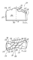
- FIGS. 2a to 2d a second embodiment of a drill head is shown, and for better readability of the description of the figures and to avoid repetition, for identical and similar components of the drill head of the second embodiment, the same reference numerals as in the embodiment according to the FIGS. 1a to 1d were used, which are increased by 100.
- the drill head 201 differs from the drill head 101 according to FIG. 1 in that in the end face 205 a groove 241 is incorporated with an axially concave bottom which extends in a first channel portion 243 from the periphery side 207 in the radial direction towards the central axis M tapered.
- the first section 243 of the channel 241 is adjoined by a second, slightly expanding section 244, which opens into a surface leg 213 or 215. Between the first groove portion 243 and the second groove portion 245, there is an obtuse angle of about 130 to 145 degrees.
- a connecting channel 247 is incorporated in the end face 205 of the drill head 201, which has a smaller radial depth than the groove 241.
- the connecting channel 247 has a substantially funnel-shaped cross-section and facilitates the flow of drilling dust through the channel towards the leading surface leg 217, 219th
- Bohrmehlabtransport is realized from the cutting region of the drill head 201, wherein a central cutting area is formed in the middle around the central axis M around.
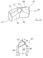
- FIGS. 3a to 3d a third embodiment of a drill head is shown, for better readability the figure description for the same or similar components, the same reference numerals as in the previously described drill heads 101, 201 are used, which like reference numerals are increased by 100 and 200, respectively.
- the drill head 301 according to the FIGS. 3a to 3d differs essentially from the drill head 101 according to the Fig. 1a to d in that the end side wings of the end face 305 formed by the main cutting edge 311 are curved in an axially concave manner. Furthermore, the drill head 301 differs from the aforementioned drill heads 101, 201 in that, in the area of the center axis M, the constant slope of the main cutting edge 311 is greater than the constant slope of the main cutting edge 311 in the peripheral region.
- the minor cutting edge 325 has a substantially S-shape in plan view.
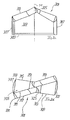
- FIGS. 4a to 4d show a fourth embodiment of the drill head, with the same reference numerals to the above-mentioned drill heads 101, 201, 301 are used for better readability for the same or similar components, which are increased by 100, 200 and 300, respectively.
- the drill head 401 differs from the drill head 201 according to FIGS FIGS. 2a to 2d in that the skin cutting edge 411 and a boundary edge of the groove 441 coincide, so that the cutting edge 411 from the periphery side 407 to the diametrically opposite Periphery page 407 may extend.
- the centrally disposed groove 441 is located in one of the main cutting edge 411 divided end side wing of the end face 405th
- the groove 441 tapers continuously from the periphery side 407 toward the surface leg 413 and 415, respectively.
- a connection channel may be used in the embodiment according to Fig. 4a to be without.
- FIGS. 5a to 5d a fifth embodiment of a drill head according to the invention is shown, wherein for better readability of the figure description for similar and identical components of the drill head same reference numerals are used as in the above-mentioned drill head embodiments, which are increased by 100, 200, 300 and 400 respectively.
- the drill head 501 differs from the drill head according to FIGS FIGS. 4a to 4d in that the boundary edge of the groove 541 does not coincide with the main cutting edge 511 but is offset therefrom.
- the groove 541 now extends from the periphery side 507 always tapering toward a surface leg 515 and 513, respectively, without having an obtuse-angled bend in the course of the groove 541. Rather, this embodiment shows an angle-free channel connection between the peripheral side 507 and the trailing in the direction of rotation ⁇ surface leg 515 and 513 of the V-shaped side surface 509th
- FIGS. 6a to 6d show a sixth embodiment of a drill head according to the invention, for better readability of the figure description for the same or similar components of the drill head, the same reference numerals are used as in the above embodiments, which are increased by 100, 200, 300, 400, 500 and 600.
- the execution according to the FIGS. 6a to 6d differs from the execution according to the FIGS. 4a to 4d in that the peripheral side 607 does not always have a continuously curved peripheral surface, but a mainly axially extending helical recess 671 as a discharge groove with a non-negligible circumferential direction component.
- the recess 671 is bounded by radially projecting webs 673, 675 in the circumferential direction.
- the recess 671 extends helically toward a conveyor coil of the drilling tool shaft, not shown.
- the webs 673, 675 are curved, wherein the curvature from the end face 605 to the mounting side 603 is continuous, with the circumferential width of the recess remaining the same throughout its course.
- the webs 673, 675 are substantially parallel to each other.
- the bottom of the recess 671 is formed radially concave.
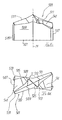
- FIGS. 7a to 7d a seventh embodiment of the drill head is shown, and for better readability of the figure description for similar and identical components of the drill head, the same reference numerals are used as in the above embodiments, which are increased by 100, 200, 300, 400, 500 and 600.
- the execution according to the FIGS. 7a to 7d differs from the execution according to the FIGS. 1a to 1d in that a projection is provided on one side half of the front side and two projections on the other side half, whose secondary cutting edges 761 extend from the secondary cutting edge 727 to the main cutting edge 711 without reaching them.
Landscapes
- Engineering & Computer Science (AREA)
- Mechanical Engineering (AREA)
- Life Sciences & Earth Sciences (AREA)
- Geology (AREA)
- Mining & Mineral Resources (AREA)
- Physics & Mathematics (AREA)
- Environmental & Geological Engineering (AREA)
- Fluid Mechanics (AREA)
- General Life Sciences & Earth Sciences (AREA)
- Geochemistry & Mineralogy (AREA)
- Processing Of Stones Or Stones Resemblance Materials (AREA)
- Drilling Tools (AREA)
Applications Claiming Priority (2)
| Application Number | Priority Date | Filing Date | Title |
|---|---|---|---|
| DE200610020538 DE102006020538A1 (de) | 2006-05-03 | 2006-05-03 | Bohrkopf für Bohrwerkzeug und Bohrwerkzeug |
| EP20070003250 EP1852202B1 (fr) | 2006-05-03 | 2007-02-15 | Tête de forage pour un outil de forage et outil de forage |
Related Parent Applications (1)
| Application Number | Title | Priority Date | Filing Date |
|---|---|---|---|
| EP20070003250 Division EP1852202B1 (fr) | 2006-05-03 | 2007-02-15 | Tête de forage pour un outil de forage et outil de forage |
Publications (3)
| Publication Number | Publication Date |
|---|---|
| EP1944108A2 true EP1944108A2 (fr) | 2008-07-16 |
| EP1944108A3 EP1944108A3 (fr) | 2008-07-23 |
| EP1944108B1 EP1944108B1 (fr) | 2009-07-22 |
Family
ID=38283925
Family Applications (3)
| Application Number | Title | Priority Date | Filing Date |
|---|---|---|---|
| EP08003706A Not-in-force EP1944107B1 (fr) | 2006-05-03 | 2007-02-15 | Tête de forage pour un outil de forage et outil de forage |
| EP08003707A Not-in-force EP1944108B1 (fr) | 2006-05-03 | 2007-02-15 | Tête de forage pour un outil de forage et outil de forage |
| EP20070003250 Not-in-force EP1852202B1 (fr) | 2006-05-03 | 2007-02-15 | Tête de forage pour un outil de forage et outil de forage |
Family Applications Before (1)
| Application Number | Title | Priority Date | Filing Date |
|---|---|---|---|
| EP08003706A Not-in-force EP1944107B1 (fr) | 2006-05-03 | 2007-02-15 | Tête de forage pour un outil de forage et outil de forage |
Family Applications After (1)
| Application Number | Title | Priority Date | Filing Date |
|---|---|---|---|
| EP20070003250 Not-in-force EP1852202B1 (fr) | 2006-05-03 | 2007-02-15 | Tête de forage pour un outil de forage et outil de forage |
Country Status (2)
| Country | Link |
|---|---|
| EP (3) | EP1944107B1 (fr) |
| DE (4) | DE102006020538A1 (fr) |
Cited By (4)
| Publication number | Priority date | Publication date | Assignee | Title |
|---|---|---|---|---|
| EP3336302A1 (fr) * | 2016-12-16 | 2018-06-20 | HILTI Aktiengesellschaft | Foret |
| US10532412B2 (en) | 2016-09-23 | 2020-01-14 | Milwaukee Electric Tool Corporation | Hole saw arbor assembly |
| US10730119B2 (en) | 2017-01-06 | 2020-08-04 | Milwaukee Electric Tool Corporation | Hole saw |
| USD965653S1 (en) | 2017-08-15 | 2022-10-04 | Milwaukee Electric Tool Corporation | Hole saw |
Families Citing this family (8)
| Publication number | Priority date | Publication date | Assignee | Title |
|---|---|---|---|---|
| DE102008043998A1 (de) * | 2008-11-24 | 2010-05-27 | Robert Bosch Gmbh | Bohrwerkzeug insbesondere für Bohr- und/oder Meißelgeräte |
| DE102008043999A1 (de) * | 2008-11-24 | 2010-05-27 | Robert Bosch Gmbh | Bohrwerkzeug insbesondere für Bohr- und/oder Meißelgeräte |
| DE102010041238A1 (de) * | 2009-12-30 | 2011-07-07 | Robert Bosch GmbH, 70469 | Gesteinsbohrwerkzeug zur dreh-schlagenden Bearbeitung von Beton, Gestein, Mauerwerk und dergleichen Materialien |
| DE102013110000A1 (de) * | 2013-09-11 | 2015-03-12 | Drebo Werkzeugfabrik Gmbh | Bohrerkopfeinsatz oder Bohrerkopfaufsatz sowie Bohrer |
| CN107073597B (zh) * | 2014-10-24 | 2019-11-01 | 京瓷株式会社 | 钻头及使用该钻头的切削加工物的制造方法 |
| DE102015223484B4 (de) * | 2015-11-26 | 2022-06-15 | Kennametal Inc. | Schneidwerkzeug und Verfahren zu dessen Herstellung |
| CN110424897B (zh) * | 2019-08-27 | 2024-06-07 | 中铁第四勘察设计院集团有限公司 | 后扩底钻头 |
| EP4059643A1 (fr) | 2021-03-18 | 2022-09-21 | Black & Decker Inc. | Tête de coupe monobloc pour un foret |
Citations (3)
| Publication number | Priority date | Publication date | Assignee | Title |
|---|---|---|---|---|
| DE4339245A1 (de) | 1993-11-18 | 1995-05-24 | Hilti Ag | Spiralbohrer |
| DE29901285U1 (de) | 1999-01-26 | 1999-06-17 | Plica Werkzeugfabrik Ag, Mollis | Bohrwerkzeug |
| EP0884448B1 (fr) | 1997-06-10 | 2004-12-08 | HILTI Aktiengesellschaft | Trépan de roche avec rainures d'évacuation hélicoidales |
Family Cites Families (8)
| Publication number | Priority date | Publication date | Assignee | Title |
|---|---|---|---|---|
| US1144088A (en) * | 1915-03-11 | 1915-06-22 | Napoleon L Ains | Drill for boring gun-barrels. |
| JPS60146605U (ja) * | 1984-03-12 | 1985-09-28 | 住友電気工業株式会社 | ドリル構造 |
| US4968193A (en) * | 1986-08-18 | 1990-11-06 | Black & Decker Corporation | Self-centering drill bit with pilot tip |
| DE19916975A1 (de) * | 1999-04-15 | 2000-10-19 | Hilti Ag | Gesteinsbohrer |
| DE10006932A1 (de) | 2000-02-16 | 2001-08-23 | Hilti Ag | Bohrwerkzeug für Gestein |
| DE10006936A1 (de) | 2000-02-16 | 2001-08-23 | Hilti Ag | Bohrwerkzeug für Gestein |
| DE10117262A1 (de) * | 2001-01-17 | 2002-07-18 | Hilti Ag | Gesteinsbohrer |
| DE102004028098A1 (de) * | 2004-06-09 | 2005-12-29 | Hilti Ag | Bohrer |
-
2006
- 2006-05-03 DE DE200610020538 patent/DE102006020538A1/de not_active Withdrawn
-
2007
- 2007-02-15 EP EP08003706A patent/EP1944107B1/fr not_active Not-in-force
- 2007-02-15 DE DE200750000627 patent/DE502007000627D1/de active Active
- 2007-02-15 EP EP08003707A patent/EP1944108B1/fr not_active Not-in-force
- 2007-02-15 DE DE200750001115 patent/DE502007001115D1/de active Active
- 2007-02-15 DE DE200750001114 patent/DE502007001114D1/de active Active
- 2007-02-15 EP EP20070003250 patent/EP1852202B1/fr not_active Not-in-force
Patent Citations (3)
| Publication number | Priority date | Publication date | Assignee | Title |
|---|---|---|---|---|
| DE4339245A1 (de) | 1993-11-18 | 1995-05-24 | Hilti Ag | Spiralbohrer |
| EP0884448B1 (fr) | 1997-06-10 | 2004-12-08 | HILTI Aktiengesellschaft | Trépan de roche avec rainures d'évacuation hélicoidales |
| DE29901285U1 (de) | 1999-01-26 | 1999-06-17 | Plica Werkzeugfabrik Ag, Mollis | Bohrwerkzeug |
Cited By (12)
| Publication number | Priority date | Publication date | Assignee | Title |
|---|---|---|---|---|
| US10532412B2 (en) | 2016-09-23 | 2020-01-14 | Milwaukee Electric Tool Corporation | Hole saw arbor assembly |
| US11154940B2 (en) | 2016-09-23 | 2021-10-26 | Milwaukee Electric Tool Corporation | Hole saw arbor assembly |
| US12447538B2 (en) | 2016-09-23 | 2025-10-21 | Milwaukee Electric Tool Corporation | Hole saw arbor assembly |
| EP3336302A1 (fr) * | 2016-12-16 | 2018-06-20 | HILTI Aktiengesellschaft | Foret |
| WO2018108656A1 (fr) * | 2016-12-16 | 2018-06-21 | Hilti Aktiengesellschaft | Trépan |
| US10730119B2 (en) | 2017-01-06 | 2020-08-04 | Milwaukee Electric Tool Corporation | Hole saw |
| US11559840B2 (en) | 2017-01-06 | 2023-01-24 | Milwaukee Electric Tool Corporation | Hole saw |
| US12233467B2 (en) | 2017-01-06 | 2025-02-25 | Milwaukee Electric Tool Corporation | Hole saw |
| US12403538B2 (en) | 2017-01-06 | 2025-09-02 | Milwaukee Electric Tool Corporation | Hole saw |
| US12403537B2 (en) | 2017-01-06 | 2025-09-02 | Milwaukee Electric Tool Corporation | Hole saw |
| USD965653S1 (en) | 2017-08-15 | 2022-10-04 | Milwaukee Electric Tool Corporation | Hole saw |
| USD973733S1 (en) | 2017-08-15 | 2022-12-27 | Milwaukee Electric Tool Corporation | Hole saw |
Also Published As
| Publication number | Publication date |
|---|---|
| EP1944107A2 (fr) | 2008-07-16 |
| EP1944108B1 (fr) | 2009-07-22 |
| EP1944107B1 (fr) | 2009-07-22 |
| DE502007000627D1 (de) | 2009-06-04 |
| EP1852202A1 (fr) | 2007-11-07 |
| DE102006020538A1 (de) | 2007-11-15 |
| DE502007001114D1 (de) | 2009-09-03 |
| EP1944108A3 (fr) | 2008-07-23 |
| DE502007001115D1 (de) | 2009-09-03 |
| EP1852202B1 (fr) | 2009-04-22 |
| EP1944107A3 (fr) | 2008-07-23 |
Similar Documents
| Publication | Publication Date | Title |
|---|---|---|
| EP1852202B1 (fr) | Tête de forage pour un outil de forage et outil de forage | |
| DE202009005847U1 (de) | Gesteinsbohrer | |
| EP1259699B1 (fr) | Perforatrice de roches | |
| EP2117752A2 (fr) | Dispositif de forage de roche | |
| DE202013103907U1 (de) | Kunststoffdübel für die Befestigung einer Schiene und Kombination aus einem solchen Kunststoffdübel und einer Schwellenschraube | |
| DE19545647A1 (de) | Drehschlag-Wendelbohrer | |
| EP0707129A2 (fr) | Outil de forage avec support et éléments de coupe | |
| EP2766572A2 (fr) | Porte-outil | |
| EP1985794B1 (fr) | Plaque en métal dur pour foret à pierre et foret à pierre | |
| EP1431511B1 (fr) | Foret à roche | |
| DE29720261U1 (de) | Fräszahn zur Erdbearbeitung | |
| EP2845672B1 (fr) | Foret | |
| EP1956186A2 (fr) | Pointe en métal dur pour un pic à queue ronde | |
| DE102008062298B4 (de) | Bohrkörper | |
| EP1574727B1 (fr) | Vis tranchante | |
| EP0778390B1 (fr) | Perceuse rotative hélicoidale à percussion | |
| EP2116321B1 (fr) | Outil de forage, notamment foret hélicoïdal | |
| EP3150347B1 (fr) | Foret | |
| EP4244490A1 (fr) | Dispositif d'ancrage à expansion et son procédé d'ancrage | |
| DE102021121487A1 (de) | Spreizanker | |
| WO2022101052A1 (fr) | Dispositif d'ancrage à expansion | |
| EP2519371B1 (fr) | Outil perforateur de roche pour la perforation roto-percutante de béton, de roche, de maçonnerie et de matériaux équivalents | |
| DE20219563U1 (de) | Bohrer | |
| DE102010017587A1 (de) | Spannhülse, Meißel-Spannhülsen-Anordnung sowie Meißel-Spannhülsen-Meißelhalter-Anordnung | |
| DE102017117664A1 (de) | Bohrer |
Legal Events
| Date | Code | Title | Description |
|---|---|---|---|
| PUAI | Public reference made under article 153(3) epc to a published international application that has entered the european phase |
Free format text: ORIGINAL CODE: 0009012 |
|
| PUAL | Search report despatched |
Free format text: ORIGINAL CODE: 0009013 |
|
| AC | Divisional application: reference to earlier application |
Ref document number: 1852202 Country of ref document: EP Kind code of ref document: P |
|
| AK | Designated contracting states |
Kind code of ref document: A2 Designated state(s): AT BE BG CH CY CZ DE DK EE ES FI FR GB GR HU IE IS IT LI LT LU LV MC NL PL PT RO SE SI SK TR |
|
| AX | Request for extension of the european patent |
Extension state: AL BA HR MK RS |
|
| AK | Designated contracting states |
Kind code of ref document: A3 Designated state(s): AT BE BG CH CY CZ DE DK EE ES FI FR GB GR HU IE IS IT LI LT LU LV MC NL PL PT RO SE SI SK TR |
|
| AX | Request for extension of the european patent |
Extension state: AL BA HR MK RS |
|
| RIN1 | Information on inventor provided before grant (corrected) |
Inventor name: PEDERSEN, HANS Inventor name: GEIER, MANFRED Inventor name: SIAN, KIRPAL SINGH |
|
| 17P | Request for examination filed |
Effective date: 20080808 |
|
| 17Q | First examination report despatched |
Effective date: 20080911 |
|
| GRAP | Despatch of communication of intention to grant a patent |
Free format text: ORIGINAL CODE: EPIDOSNIGR1 |
|
| GRAS | Grant fee paid |
Free format text: ORIGINAL CODE: EPIDOSNIGR3 |
|
| AKX | Designation fees paid |
Designated state(s): DE FR GB |
|
| GRAA | (expected) grant |
Free format text: ORIGINAL CODE: 0009210 |
|
| AC | Divisional application: reference to earlier application |
Ref document number: 1852202 Country of ref document: EP Kind code of ref document: P |
|
| AK | Designated contracting states |
Kind code of ref document: B1 Designated state(s): DE FR GB |
|
| REG | Reference to a national code |
Ref country code: GB Ref legal event code: FG4D Free format text: NOT ENGLISH |
|
| REF | Corresponds to: |
Ref document number: 502007001115 Country of ref document: DE Date of ref document: 20090903 Kind code of ref document: P |
|
| PLBE | No opposition filed within time limit |
Free format text: ORIGINAL CODE: 0009261 |
|
| STAA | Information on the status of an ep patent application or granted ep patent |
Free format text: STATUS: NO OPPOSITION FILED WITHIN TIME LIMIT |
|
| 26N | No opposition filed |
Effective date: 20100423 |
|
| PGFP | Annual fee paid to national office [announced via postgrant information from national office to epo] |
Ref country code: FR Payment date: 20100914 Year of fee payment: 4 |
|
| GBPC | Gb: european patent ceased through non-payment of renewal fee |
Effective date: 20110215 |
|
| REG | Reference to a national code |
Ref country code: FR Ref legal event code: ST Effective date: 20111102 |
|
| REG | Reference to a national code |
Ref country code: DE Ref legal event code: R073 Ref document number: 502007001115 Country of ref document: DE |
|
| REG | Reference to a national code |
Ref country code: DE Ref legal event code: R119 Ref document number: 502007001115 Country of ref document: DE Effective date: 20110901 |
|
| PG25 | Lapsed in a contracting state [announced via postgrant information from national office to epo] |
Ref country code: FR Free format text: LAPSE BECAUSE OF NON-PAYMENT OF DUE FEES Effective date: 20110228 |
|
| REG | Reference to a national code |
Ref country code: GB Ref legal event code: S28 Free format text: APPLICATION FILED |
|
| REG | Reference to a national code |
Ref country code: DE Ref legal event code: R073 Ref document number: 502007001115 Country of ref document: DE |
|
| PG25 | Lapsed in a contracting state [announced via postgrant information from national office to epo] |
Ref country code: GB Free format text: LAPSE BECAUSE OF NON-PAYMENT OF DUE FEES Effective date: 20110215 |
|
| REG | Reference to a national code |
Ref country code: GB Ref legal event code: S28 Free format text: RESTORATION ALLOWED Effective date: 20120402 |
|
| REG | Reference to a national code |
Ref country code: DE Ref legal event code: R074 Ref document number: 502007001115 Country of ref document: DE |
|
| REG | Reference to a national code |
Ref country code: DE Ref legal event code: R074 Ref document number: 502007001115 Country of ref document: DE Effective date: 20120713 |
|
| PGFP | Annual fee paid to national office [announced via postgrant information from national office to epo] |
Ref country code: GB Payment date: 20180214 Year of fee payment: 12 Ref country code: DE Payment date: 20180130 Year of fee payment: 12 |
|
| REG | Reference to a national code |
Ref country code: DE Ref legal event code: R119 Ref document number: 502007001115 Country of ref document: DE |
|
| GBPC | Gb: european patent ceased through non-payment of renewal fee |
Effective date: 20190215 |
|
| PG25 | Lapsed in a contracting state [announced via postgrant information from national office to epo] |
Ref country code: GB Free format text: LAPSE BECAUSE OF NON-PAYMENT OF DUE FEES Effective date: 20190215 Ref country code: DE Free format text: LAPSE BECAUSE OF NON-PAYMENT OF DUE FEES Effective date: 20190903 |